CN113183022B - Automatic operation electro-hydraulic servo fine grinding table with replaceable grinding tool - Google Patents
Automatic operation electro-hydraulic servo fine grinding table with replaceable grinding tool Download PDFInfo
- Publication number
- CN113183022B CN113183022B CN202110512302.7A CN202110512302A CN113183022B CN 113183022 B CN113183022 B CN 113183022B CN 202110512302 A CN202110512302 A CN 202110512302A CN 113183022 B CN113183022 B CN 113183022B
- Authority
- CN
- China
- Prior art keywords
- hydraulic
- grinding
- servo
- electro
- disc
- Prior art date
- Legal status (The legal status is an assumption and is not a legal conclusion. Google has not performed a legal analysis and makes no representation as to the accuracy of the status listed.)
- Active
Links
Images


Classifications
-
- B—PERFORMING OPERATIONS; TRANSPORTING
- B24—GRINDING; POLISHING
- B24B—MACHINES, DEVICES, OR PROCESSES FOR GRINDING OR POLISHING; DRESSING OR CONDITIONING OF ABRADING SURFACES; FEEDING OF GRINDING, POLISHING, OR LAPPING AGENTS
- B24B37/00—Lapping machines or devices; Accessories
- B24B37/04—Lapping machines or devices; Accessories designed for working plane surfaces
- B24B37/07—Lapping machines or devices; Accessories designed for working plane surfaces characterised by the movement of the work or lapping tool
- B24B37/10—Lapping machines or devices; Accessories designed for working plane surfaces characterised by the movement of the work or lapping tool for single side lapping
-
- B—PERFORMING OPERATIONS; TRANSPORTING
- B24—GRINDING; POLISHING
- B24B—MACHINES, DEVICES, OR PROCESSES FOR GRINDING OR POLISHING; DRESSING OR CONDITIONING OF ABRADING SURFACES; FEEDING OF GRINDING, POLISHING, OR LAPPING AGENTS
- B24B37/00—Lapping machines or devices; Accessories
- B24B37/005—Control means for lapping machines or devices
-
- B—PERFORMING OPERATIONS; TRANSPORTING
- B24—GRINDING; POLISHING
- B24B—MACHINES, DEVICES, OR PROCESSES FOR GRINDING OR POLISHING; DRESSING OR CONDITIONING OF ABRADING SURFACES; FEEDING OF GRINDING, POLISHING, OR LAPPING AGENTS
- B24B37/00—Lapping machines or devices; Accessories
- B24B37/27—Work carriers
- B24B37/30—Work carriers for single side lapping of plane surfaces
-
- B—PERFORMING OPERATIONS; TRANSPORTING
- B24—GRINDING; POLISHING
- B24B—MACHINES, DEVICES, OR PROCESSES FOR GRINDING OR POLISHING; DRESSING OR CONDITIONING OF ABRADING SURFACES; FEEDING OF GRINDING, POLISHING, OR LAPPING AGENTS
- B24B41/00—Component parts such as frames, beds, carriages, headstocks
- B24B41/02—Frames; Beds; Carriages
-
- B—PERFORMING OPERATIONS; TRANSPORTING
- B24—GRINDING; POLISHING
- B24B—MACHINES, DEVICES, OR PROCESSES FOR GRINDING OR POLISHING; DRESSING OR CONDITIONING OF ABRADING SURFACES; FEEDING OF GRINDING, POLISHING, OR LAPPING AGENTS
- B24B41/00—Component parts such as frames, beds, carriages, headstocks
- B24B41/04—Headstocks; Working-spindles; Features relating thereto
- B24B41/047—Grinding heads for working on plane surfaces
-
- B—PERFORMING OPERATIONS; TRANSPORTING
- B24—GRINDING; POLISHING
- B24B—MACHINES, DEVICES, OR PROCESSES FOR GRINDING OR POLISHING; DRESSING OR CONDITIONING OF ABRADING SURFACES; FEEDING OF GRINDING, POLISHING, OR LAPPING AGENTS
- B24B47/00—Drives or gearings; Equipment therefor
- B24B47/02—Drives or gearings; Equipment therefor for performing a reciprocating movement of carriages or work- tables
- B24B47/06—Drives or gearings; Equipment therefor for performing a reciprocating movement of carriages or work- tables by liquid or gas pressure only
-
- B—PERFORMING OPERATIONS; TRANSPORTING
- B24—GRINDING; POLISHING
- B24B—MACHINES, DEVICES, OR PROCESSES FOR GRINDING OR POLISHING; DRESSING OR CONDITIONING OF ABRADING SURFACES; FEEDING OF GRINDING, POLISHING, OR LAPPING AGENTS
- B24B47/00—Drives or gearings; Equipment therefor
- B24B47/10—Drives or gearings; Equipment therefor for rotating or reciprocating working-spindles carrying grinding wheels or workpieces
- B24B47/14—Drives or gearings; Equipment therefor for rotating or reciprocating working-spindles carrying grinding wheels or workpieces by liquid or gas pressure
-
- B—PERFORMING OPERATIONS; TRANSPORTING
- B24—GRINDING; POLISHING
- B24B—MACHINES, DEVICES, OR PROCESSES FOR GRINDING OR POLISHING; DRESSING OR CONDITIONING OF ABRADING SURFACES; FEEDING OF GRINDING, POLISHING, OR LAPPING AGENTS
- B24B49/00—Measuring or gauging equipment for controlling the feed movement of the grinding tool or work; Arrangements of indicating or measuring equipment, e.g. for indicating the start of the grinding operation
-
- F—MECHANICAL ENGINEERING; LIGHTING; HEATING; WEAPONS; BLASTING
- F15—FLUID-PRESSURE ACTUATORS; HYDRAULICS OR PNEUMATICS IN GENERAL
- F15B—SYSTEMS ACTING BY MEANS OF FLUIDS IN GENERAL; FLUID-PRESSURE ACTUATORS, e.g. SERVOMOTORS; DETAILS OF FLUID-PRESSURE SYSTEMS, NOT OTHERWISE PROVIDED FOR
- F15B11/00—Servomotor systems without provision for follow-up action; Circuits therefor
- F15B11/08—Servomotor systems without provision for follow-up action; Circuits therefor with only one servomotor
-
- F—MECHANICAL ENGINEERING; LIGHTING; HEATING; WEAPONS; BLASTING
- F15—FLUID-PRESSURE ACTUATORS; HYDRAULICS OR PNEUMATICS IN GENERAL
- F15B—SYSTEMS ACTING BY MEANS OF FLUIDS IN GENERAL; FLUID-PRESSURE ACTUATORS, e.g. SERVOMOTORS; DETAILS OF FLUID-PRESSURE SYSTEMS, NOT OTHERWISE PROVIDED FOR
- F15B13/00—Details of servomotor systems ; Valves for servomotor systems
- F15B13/02—Fluid distribution or supply devices characterised by their adaptation to the control of servomotors
Landscapes
- Engineering & Computer Science (AREA)
- Mechanical Engineering (AREA)
- Physics & Mathematics (AREA)
- Fluid Mechanics (AREA)
- General Engineering & Computer Science (AREA)
- Grinding Of Cylindrical And Plane Surfaces (AREA)
- Constituent Portions Of Griding Lathes, Driving, Sensing And Control (AREA)
Abstract
An automatic operation electro-hydraulic servo fine grinding table with a replaceable grinding tool belongs to the field of grinding equipment and comprises a rack, a hydraulic motor driving device, a lower rotary table mechanism, a lifting mechanism and an upper grinding disc mechanism; the lower rotary table mechanism is driven by a hydraulic motor to rotate, the lifting mechanism is driven by a lifting servo hydraulic cylinder, a grinding tool can be lifted to a specified height, and the upper grinding disc mechanism is driven by a push-pull servo hydraulic cylinder to reciprocate; the invention mainly adopts the rotary motion and the reciprocating motion to grind the surface of the same workpiece, adopts full hydraulic drive, has strong bearing capacity, high automation degree and fast system response speed, can turn over and erect the upper grinding disc, is convenient for loading and unloading, has variable fixed height of the grinding tool, has large axial size range of the grinding workpiece, meets the grinding processing requirements of workpieces with different heights, improves the production efficiency and the equipment utilization rate, and lightens the operation burden of workers.
Description
Technical Field
The invention relates to the field of grinding equipment, in particular to an automatic operation electro-hydraulic servo fine grinding table with a replaceable grinding tool.
Background
Grinding is a micro-machining process, grinding produces relative motion between the machined surface of a workpiece and a grinding tool by means of the grinding tool and a grinding agent (a free grinding material), and a certain pressure is applied to remove a tiny surface convex layer from the workpiece so as to obtain a very low surface roughness value, very high dimensional precision, geometrical shape precision and the like.
The prior grinding device has the following defects:
1. usually, only one motion mode (rotation or reciprocation) is adopted to grind the surface of a workpiece, the same surface of the workpiece is not ground by adopting the combined motion of rotation and reciprocation, and in many use occasions, the mode of manually pushing and pulling a grinding tool is still adopted to grind, so that the automation degree of equipment is low, and the grinding efficiency is low.
2. The feeding and discharging are inconvenient, the feeding and discharging can be usually carried out only after the distance between the upper grinding disc and the lower grinding disc is increased, the vertical space position above the upper grinding disc cannot be vacated, and the existing crane in a factory is inconvenient to directly hoist large ground workpieces.
Disclosure of Invention
In order to solve the problems, the invention provides an automatic operation electro-hydraulic servo fine grinding table with a replaceable grinding tool.
In order to achieve the purpose, the invention provides the following technical scheme: the invention discloses an automatic operation electro-hydraulic servo finish grinding table with replaceable grinding tools, which comprises a rack (1), a hydraulic motor driving device (2) arranged on the rack (1), a lower turntable mechanism (3), a lifting mechanism (4) and an upper grinding disc mechanism (5), and is characterized in that: the lower turntable mechanism (3) is powered by the hydraulic motor driving device (2) to drive a workpiece to rotate; the lifting mechanism (4) is driven by a lifting servo hydraulic cylinder, the grinding tool can be lifted to a fixed height, the upper grinding disc mechanism (5) is driven by a push-pull servo hydraulic cylinder and is pressed on the surface of a workpiece to reciprocate, and the upper grinding disc can be turned and erected.
The rack (1) comprises a vertical column (101), a pull rod (102), a guide post (103), a cross rod (104) and a stop lug (105), wherein a through hole, a blind hole, a rotary disc groove and a threaded hole are formed in the vertical column (101), the cross rod (104) is provided with the threaded hole, the blind hole and the through hole, the pull rod (102) penetrates through the through hole to be connected with the vertical column (101), the cross rod (103) is connected to the top surface of the vertical column (101) through a bolt, the lower end of the guide post (103) is arranged in the blind hole of the vertical column (101), the upper end of the guide post (103) is arranged in the blind hole of the cross rod (104), and the stop lug (105) is connected to the side surface of the vertical column through a bolt.
The hydraulic motor driving device (2) comprises a hydraulic motor (201) and a first electro-hydraulic servo valve (202), wherein the first electro-hydraulic servo valve (202) is arranged on the hydraulic motor (201), and a flange is arranged on a rotating shaft of the hydraulic motor (201).
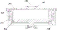
Lower rotary table mechanism (3) are including revolving stage seat (301), thrust bearing (302), antifriction bearing (303), revolving stage (304), press from both sides tight dish (305), work piece (306) and anchor clamps (307), revolving stage (304) bottom is equipped with the flange, press from both sides and seted up T type groove on the tight dish (305), anchor clamps (307) are fixed in on pressing from both sides tight dish (305) through the bolt, and revolving stage seat (301) bottom is equipped with the screw thread blind hole, and revolving stage seat (301) are fixed in on stand (101) revolving stage groove with the bolt.
The lifting mechanism (4) comprises a sliding rod (401), a lifting servo hydraulic cylinder (402), a second electro-hydraulic servo valve (403) and a first displacement sensor (404), the second electro-hydraulic servo valve (403) and the first displacement sensor (404) are arranged on the side face of the lifting servo hydraulic cylinder (402), and the lifting servo hydraulic cylinder (402) is fixed to the middle position of the top face of the cross rod (104) through bolts.
The upper grinding disc mechanism (5) comprises a grinding tool (501), a carrying disc (502), a balance weight (503), a displacement sensor II (504), a push-pull servo hydraulic cylinder (505), an electro-hydraulic servo valve III (506) and a fixed seat (507), the displacement sensor II (504) and the electro-hydraulic servo valve III (506) are arranged on the lifting servo hydraulic cylinder (402), two ends of the push-pull servo hydraulic cylinder (505) are respectively connected with the carrying disc (502) and the fixed seat (507) through pin shafts, and the position of the fixed seat (507) is higher than that of the blocking lug (105).
Compared with the prior art, the invention has the beneficial effects that: when the automatic operation electro-hydraulic servo fine grinding table with the replaceable grinding tool grinds, the lower grinding disc mechanism is driven by the hydraulic motor to rotate, the upper grinding disc mechanism is driven by the push-pull servo hydraulic cylinder to reciprocate, and the rotating motion and the reciprocating motion are adopted to simultaneously work and grind the same surface of a workpiece, so that the grinding efficiency is improved; the lifting mechanism is driven by a lifting servo hydraulic cylinder, the grinding tool can be lifted to a specified height, when the upper grinding disc is lifted to a set height, the push-pull servo hydraulic cylinder drives the grinding tool to retract, when the side surface of the carrier disc is contacted with the side surface of the stop lug, the grinding disc is erected to leave an upper vertical space position under the action of a pulling torque, and the ground workpiece can be directly lifted by using the existing crane of a factory conveniently; the system is driven in a full hydraulic manner, so that the system is quick in response, high in rigidity and strong in load capacity, and large workpieces can be conveniently ground and processed; the lifting mechanism is driven by a lifting servo hydraulic cylinder, grinding tools can be lifted to different heights, workpieces with different heights can be ground, the electro-hydraulic servo valve can control the hydraulic motor to rotate positively and negatively, the upper grinding disc mechanism adopts a split design, different grinding tools and counter weights can be replaced, the grinding processing mode is flexible and changeable, and the equipment utilization rate is improved; the hydraulic system has high automation degree and reduces the operation burden of workers.
Drawings
FIG. 1 is an isometric view of an automatically operating electro-hydraulic servo lapping table of a replaceable abrasive article according to the present invention;
FIG. 2 is a front view of an automatically operating electro-hydraulic servo lapping table of a replaceable abrasive article of the present invention;
FIG. 3 is a top view of an automatically operating electro-hydraulic servo lapping table of a replaceable abrasive article of the present invention;
FIG. 4 is a hydraulic schematic diagram of an automatically operating electro-hydraulic servo finish grinding table of a replaceable grinding tool of the present invention;
FIG. 5 is a sequence diagram of the operation of an automatically operating electro-hydraulic servo lapping table for a replaceable abrasive article according to the present invention;
FIG. 6 is an isometric view of the frame of FIG. 1;
FIG. 7 is an exploded view of the housing of FIG. 1;
FIG. 8 is a front isometric view of the hydraulic motor drive of FIG. 1;
FIG. 9 is a front isometric view of the lower turntable mechanism of FIG. 1;
FIG. 10 is a cross-sectional view of the lower turntable mechanism of FIG. 1;
FIG. 11 is an exploded view of the lower turntable mechanism of FIG. 1;
FIG. 12 is a top view of the turret block of FIG. 9;
FIG. 13 is a schematic view of the turntable of FIG. 9;
FIG. 14 is a front isometric view of the lift mechanism of FIG. 1;
FIG. 15 is an exploded view of the lift mechanism of FIG. 1;
FIG. 16 is a front isometric view of the upper abrasive disc mechanism of FIG. 1;
fig. 17 is an exploded view of the upper abrasive disc mechanism of fig. 1.
Detailed Description
The technical solutions in the embodiments of the present invention will be clearly and completely described below with reference to the drawings in the embodiments of the present invention, and it is obvious that the described embodiments are only a part of the embodiments of the present invention, and not all of the embodiments. All other embodiments, which can be derived by a person skilled in the art from the embodiments given herein without making any creative effort, shall fall within the protection scope of the present invention.
Referring to fig. 1, 2 and 3, the invention is an automatic operation electro-hydraulic servo fine grinding table device with replaceable grinding tools, which comprises a frame (1), a hydraulic motor driving device (2) arranged on the frame (1), a lower grinding table mechanism (3), a lifting mechanism (4) and an upper grinding table mechanism (5); the lower rotary table mechanism (3) is powered by the hydraulic motor driving device (2) to drive a workpiece to rotate, the lifting mechanism (4) is driven by a lifting servo hydraulic cylinder to lift the grinding tool to a specified height, the upper grinding disc mechanism (5) is driven by a push-pull servo hydraulic cylinder and presses the surface of the workpiece to reciprocate, and the upper grinding disc can be turned and erected.
Referring to fig. 6 and 7, the rack (1) comprises a column (101), a pull rod (102), a guide pillar (103), a cross rod (104) and a stop lug (105), the column (101) is provided with a through hole, a blind hole, a rotary disc groove and a threaded hole, the cross rod (104) is provided with the threaded hole, the blind hole and the through hole, the pull rod (102) penetrates through the fixed hole to be connected with the column (101), the cross rod (103) is connected to the top surface of the column (101) through a bolt, the lower end of the guide pillar (103) is erected in the blind hole of the column (101), the upper end of the guide pillar (103) is erected in the blind hole of the cross rod (104), and the stop lug (105) is connected to the side surface of the column through a bolt.
Referring to fig. 8, the hydraulic motor driving device (2) includes a hydraulic motor (201) and a first electro-hydraulic servo valve (202), a flange is disposed on a rotating shaft of the hydraulic motor (201), the first electro-hydraulic servo valve (202) is disposed on the hydraulic motor (201), and a base of the hydraulic motor (201) is fixedly connected to the ground through a bolt.
Referring to fig. 8, 9, 10, 11, 12 and 13, the turntable mechanism (3) includes a turntable base (301), a thrust bearing (302), a rolling bearing (303), a turntable (304), a clamping disc (305), a workpiece (306) and a clamp (307), a flange is disposed at the bottom of the turntable (304), the turntable (304) is connected with a rotating shaft of the hydraulic motor driving device (201) through the flange to transmit torque, a T-shaped groove is disposed on the clamping disc (305), the clamp (307) is fixed on the clamping disc (305) through a bolt, a threaded blind hole is disposed at the bottom of the turntable base (301), and the turntable base (301) is fixed on the turntable groove of the upright post (101) through the bolt.
Referring to fig. 14 and 15, the lifting mechanism (4) includes a sliding rod (401), a lifting servo hydraulic cylinder (402), a second electro-hydraulic servo valve (403) and a first displacement sensor (404), wherein the second electro-hydraulic servo valve (403) and the first displacement sensor (404) are disposed on a side surface of the lifting servo hydraulic cylinder (402) and fixed to a middle position of a top surface of the cross bar (104) by bolts.
Referring to fig. 16 and 17, the upper grinding disc mechanism (5) includes a grinding tool (501), a carrying disc (502), a counterweight (503), a second displacement sensor (504), a push-pull servo hydraulic cylinder (505), a third electro-hydraulic servo valve (506) and a fixed seat (507), the second displacement sensor (504) and the third electro-hydraulic servo valve (506) are disposed on the lifting servo hydraulic cylinder (402), two ends of the push-pull servo hydraulic cylinder (505) are respectively connected to the carrying disc (502) and the fixed seat (507) through pins, and the fixed seat (507) is higher than the retaining lug (105).
Referring to fig. 1 to 17, in operation: (1) the start-stop switch is pressed, the fixed displacement pump (603) works, the controller (607) sends a signal to control the servo valve, the electro-hydraulic servo valve III (506) works at the left position, the push-pull servo hydraulic cylinder (505) retracts, the side surface of the carrier disc (502) touches the stop lug (105), the carrier disc (502) and the grinding tool (501) are erected under the action of pulling torque, and a worker can replace the loose grinding tool (501) or loosen the clamp (307) to finish assembling and disassembling the workpiece (306); (2) the electro-hydraulic servo valve III (506) works at the right position, and the push-pull servo hydraulic cylinder (505) extends out to return to the middle position to drive the grinding tool (501) to be leveled and centered; (3) the electro-hydraulic servo valve II (403) works at the right position, the lifting servo hydraulic cylinder (402) extends out, the push-pull servo hydraulic cylinder (505) also extends out in a matched manner, at the moment, the grinding tool (501) still keeps centered, the slide bar (401) supports the carrying disc (502) to descend, the lower surface of the grinding tool (501) is in contact with the upper surface of the workpiece (306), the upper surface of the slide bar (401) is separated from the bottom surface of the carrying disc (502), but the side surface of the slide bar (401) is also in contact with the side surface of the carrying disc (502) (convenient for guiding reciprocating motion); (4) the first electro-hydraulic servo valve (202) works at the left position, the hydraulic motor (201) rotates, torque is transmitted through the flange to drive the rotary table (304) to rotate, the clamping disc (305) and the workpiece (306) also start to rotate, the third electro-hydraulic servo valve (506) reverses in turns, the servo hydraulic cylinder (505) is pushed and pulled to stretch, the grinding tool (501) is driven to reciprocate, the surface of the workpiece (306) is ground, and a technician can set the grinding duration of the controller (607) according to process requirements; (5) after the grinding time is over, the first electro-hydraulic servo valve (202) returns to the middle position, the hydraulic motor (201) stops rotating to drive the rotary table (304), the clamping disc (305) and the workpiece (306) to stop rotating, the third electro-hydraulic servo valve (506) returns to the middle position, and the servo hydraulic cylinder (505) is pushed and pulled to return to the middle position to drive the grinding tool (501) to be centered; the electro-hydraulic servo valve II (403) works at the left position, (6) the lifting servo hydraulic cylinder (402) retracts, the electro-hydraulic servo valve III (506) works at the left position, the push-pull servo hydraulic cylinder (505) also retracts in a matched manner, the grinding tool (501) is still centered at the moment, the lower surface of the grinding tool (501) is separated from the upper surface of the workpiece (306), the upper surface of the sliding rod (401) is contacted with the bottom surface of the carrying disc (502), the carrying disc (502) is supported by the sliding rod (401) to ascend, when the sliding rod (401) returns to the top position, the lower surface of the carrying disc (502) is flush with the upper surface of the stop lug (105) (convenient for loading and motion guiding), and a distance is reserved between the workpiece (306) and the grinding tool (501); and (3) detecting the quality of the grinding surface of the workpiece (306), returning to the repeated steps (1) - (6) if the grinding surface is qualified, returning to the repeated steps (4) - (6) if the grinding surface is not qualified, and pressing a start-stop switch by a technician after all parts are machined, so that the equipment is closed.
Although embodiments of the present invention have been shown and described, it will be appreciated by those skilled in the art that various changes, modifications, substitutions and alterations can be made in these embodiments without departing from the principles and spirit of the invention, the scope of which is defined in the appended claims and their equivalents.
Description of the reference numerals
1: a rack 2: hydraulic motor drive device 3: lower turntable mechanism 4: the lifting mechanism 5: upper grinding disc mechanism
101: the upright post 102: the pull rod 103: guide post 104: cross bar 105: catch ear
201: the hydraulic motor 202: electro-hydraulic servo valve 1
301: the turret base 302: thrust bearing 303: rolling bearing 304: the turntable 305: clamping the disc 306: workpiece 307: clamp apparatus
401: the slide bar 402: lifting servo hydraulic cylinder 403: the second electro-hydraulic servo valve 404: the first displacement sensor 501: abrasive tool 502: the carrier tray 503: counterweight 504: a second displacement sensor 505: push-pull servo hydraulic cylinder 506: electro-hydraulic servo valve three 507: fixing seat
601: an oil tank 602: an oil filter 603: the metering pump 604: relief valve 605: pressure gauge 606: the check valve 607: controller
Claims (2)
1. The utility model provides a servo finish grinding platform of automatic operation electricity liquid of removable grinding apparatus, its includes frame (1), set up in hydraulic motor drive arrangement (2), lower rotary table mechanism (3), elevating system (4) and upper millstone mechanism (5) on frame (1), its characterized in that: the lower rotary table mechanism (3) is powered by the hydraulic motor driving device (2) to drive a workpiece to rotate, the lifting mechanism (4) is driven by a lifting servo hydraulic cylinder to lift the grinding tool to a fixed height, the upper grinding disc mechanism (5) is driven by a push-pull servo hydraulic cylinder to press the surface of the workpiece to reciprocate, and the upper grinding disc can be turned over and erected; the rack (1) comprises a vertical column (101), a pull rod (102), a guide post (103), a cross rod (104) and a stop lug (105), wherein the vertical column (101) is provided with a through hole, a blind hole, a rotary disc groove and a threaded hole, the cross rod (104) is provided with the threaded hole, the blind hole and the through hole, the pull rod (102) penetrates through the through hole to be connected with the vertical column (101), the cross rod (104) is connected to the top surface of the vertical column (101) through a bolt, the lower end of the guide post (103) is erected in the blind hole of the vertical column (101), the upper end of the guide post (103) is erected in the blind hole of the cross rod (104), and the stop lug (105) is connected to the side surface of the vertical column through a bolt; the lower rotary table mechanism (3) comprises a rotary table base (301), a thrust bearing (302), a rolling bearing (303), a rotary table (304), a clamping disc (305), a workpiece (306) and a clamp (307), wherein a flange is arranged at the bottom of the rotary table (304), a T-shaped groove is formed in the clamping disc (305), and the clamp (307) is fixed on the clamping disc (305) through a bolt; the lifting mechanism (4) comprises a sliding rod (401), a lifting servo hydraulic cylinder (402), a second electro-hydraulic servo valve (403) and a first displacement sensor (404), and the second electro-hydraulic servo valve (403) and the first displacement sensor (404) are arranged on the lifting servo hydraulic cylinder (402); the upper grinding disc mechanism (5) comprises a grinding tool (501), a carrying disc (502), a balance weight (503), a displacement sensor II (504), a push-pull servo hydraulic cylinder (505), an electro-hydraulic servo valve III (506) and a fixed seat (507), wherein the displacement sensor II (504) and the electro-hydraulic servo valve III (506) are arranged on the push-pull servo hydraulic cylinder (505), and two ends of the push-pull servo hydraulic cylinder (505) are respectively connected with the carrying disc (502) and the fixed seat (507) through pin shafts.
2. The automatically operating electro-hydraulic servo lapping station of a replaceable abrasive article of claim 1, wherein: the hydraulic motor driving device (2) comprises a hydraulic motor (201) and a first electro-hydraulic servo valve (202), the first electro-hydraulic servo valve (202) is arranged on the hydraulic motor (201), and a flange is arranged on a rotating shaft of the hydraulic motor (201).
Priority Applications (1)
| Application Number | Priority Date | Filing Date | Title |
|---|---|---|---|
| CN202110512302.7A CN113183022B (en) | 2021-05-11 | 2021-05-11 | Automatic operation electro-hydraulic servo fine grinding table with replaceable grinding tool |
Applications Claiming Priority (1)
| Application Number | Priority Date | Filing Date | Title |
|---|---|---|---|
| CN202110512302.7A CN113183022B (en) | 2021-05-11 | 2021-05-11 | Automatic operation electro-hydraulic servo fine grinding table with replaceable grinding tool |
Publications (2)
| Publication Number | Publication Date |
|---|---|
| CN113183022A CN113183022A (en) | 2021-07-30 |
| CN113183022B true CN113183022B (en) | 2023-02-03 |
Family
ID=76981181
Family Applications (1)
| Application Number | Title | Priority Date | Filing Date |
|---|---|---|---|
| CN202110512302.7A Active CN113183022B (en) | 2021-05-11 | 2021-05-11 | Automatic operation electro-hydraulic servo fine grinding table with replaceable grinding tool |
Country Status (1)
| Country | Link |
|---|---|
| CN (1) | CN113183022B (en) |
Citations (8)
| Publication number | Priority date | Publication date | Assignee | Title |
|---|---|---|---|---|
| JP2001239458A (en) * | 2000-02-25 | 2001-09-04 | Nikon Corp | Chemical mechanical polishing device for substrate |
| JP2006297512A (en) * | 2005-04-18 | 2006-11-02 | Nakamura Tome Precision Ind Co Ltd | Spherical machining device for lens |
| JP2007318041A (en) * | 2006-05-29 | 2007-12-06 | Disco Abrasive Syst Ltd | Polishing device |
| CN106863109A (en) * | 2017-03-17 | 2017-06-20 | 衢州学院 | The plane lapping polishing machine and its method of a kind of work piece holder linear reciprocating motion |
| CN210550365U (en) * | 2019-06-25 | 2020-05-19 | 吉姆西半导体科技(无锡)有限公司 | Wafer planarization equipment |
| CN111716202A (en) * | 2020-07-02 | 2020-09-29 | 耿广富 | Automatic grinding device for arc surface of workpiece |
| CN212683490U (en) * | 2020-07-22 | 2021-03-12 | 阜宁县宏智机械有限公司 | Grinding device is used in machine parts processing |
| CN213106280U (en) * | 2020-08-20 | 2021-05-04 | 昆山瑞伯恩精密机械有限公司 | Precision grinding equipment for grinding ring |
Family Cites Families (5)
| Publication number | Priority date | Publication date | Assignee | Title |
|---|---|---|---|---|
| JP3043578B2 (en) * | 1993-10-25 | 2000-05-22 | 東芝機械株式会社 | Polishing equipment |
| JP4149618B2 (en) * | 1999-07-19 | 2008-09-10 | 株式会社ツガミ | Constant pressure quantitative continuous pressurizing method for flat lapping machine and constant pressure quantitative continuous pressurizing apparatus for flat lapping machine |
| CN108284966B (en) * | 2017-12-26 | 2021-04-20 | 中国航发四川燃气涡轮研究院 | Hydraulic assembly frame for small aero-engine |
| CN108789087A (en) * | 2018-07-13 | 2018-11-13 | 成都蒲江珂贤科技有限公司 | A kind of industrial machinery automatic sander and polishing process |
| CN110405626A (en) * | 2019-08-20 | 2019-11-05 | 杨增学 | A kind of abnormal shape plate side processing machine |
-
2021
- 2021-05-11 CN CN202110512302.7A patent/CN113183022B/en active Active
Patent Citations (8)
| Publication number | Priority date | Publication date | Assignee | Title |
|---|---|---|---|---|
| JP2001239458A (en) * | 2000-02-25 | 2001-09-04 | Nikon Corp | Chemical mechanical polishing device for substrate |
| JP2006297512A (en) * | 2005-04-18 | 2006-11-02 | Nakamura Tome Precision Ind Co Ltd | Spherical machining device for lens |
| JP2007318041A (en) * | 2006-05-29 | 2007-12-06 | Disco Abrasive Syst Ltd | Polishing device |
| CN106863109A (en) * | 2017-03-17 | 2017-06-20 | 衢州学院 | The plane lapping polishing machine and its method of a kind of work piece holder linear reciprocating motion |
| CN210550365U (en) * | 2019-06-25 | 2020-05-19 | 吉姆西半导体科技(无锡)有限公司 | Wafer planarization equipment |
| CN111716202A (en) * | 2020-07-02 | 2020-09-29 | 耿广富 | Automatic grinding device for arc surface of workpiece |
| CN212683490U (en) * | 2020-07-22 | 2021-03-12 | 阜宁县宏智机械有限公司 | Grinding device is used in machine parts processing |
| CN213106280U (en) * | 2020-08-20 | 2021-05-04 | 昆山瑞伯恩精密机械有限公司 | Precision grinding equipment for grinding ring |
Non-Patent Citations (1)
| Title |
|---|
| 轴承滚子端面在双盘研磨机上的研磨;穆雪健等;《精密制造与自动化》;20130825(第03期);全文 * |
Also Published As
| Publication number | Publication date |
|---|---|
| CN113183022A (en) | 2021-07-30 |
Similar Documents
| Publication | Publication Date | Title |
|---|---|---|
| CN206405849U (en) | A kind of cabinet-wood sanding apparatus | |
| CN209615112U (en) | A kind of Novel five-axis polishing machine | |
| CN109483381A (en) | A kind of Novel five-axis polishing machine | |
| CN108188900B (en) | Waste steel plate grinding device | |
| CN110935921A (en) | Automatic spherical surface body profiling polishing machine and polishing method | |
| CN113183022B (en) | Automatic operation electro-hydraulic servo fine grinding table with replaceable grinding tool | |
| CN211805341U (en) | Automatic workpiece measuring device of grinding machine | |
| CN210214678U (en) | Scissor hydraulic lift with rotary table top | |
| CN112355794A (en) | Polishing device for machine-building | |
| CN213258519U (en) | Deep hole processing machinery device | |
| CN214488969U (en) | Multi-milling-head face milling device | |
| CN201863066U (en) | Grinding machine for end face of mandrel | |
| CN211564630U (en) | Automatic profiling polishing machine for spherical surface body | |
| CN107756253A (en) | A kind of double abrasive wheel trimming machine | |
| CN210790352U (en) | Cylinder shaping device for production of oil-gas separation tank of double-screw air compressor | |
| CN109648453B (en) | Rotatable lifting device for polishing machine | |
| CN219131916U (en) | Grinding device | |
| CN217552108U (en) | Grinding machine for valve machining | |
| CN210475377U (en) | Leveling device of isothermal forging hydraulic machine | |
| CN213828396U (en) | Based on automation equipment is with adjustable grinding machine | |
| CN218082123U (en) | Multi-station continuous grinding device | |
| CN215547651U (en) | Polishing and grinding device for petroleum machinery parts | |
| CN217097204U (en) | Grinding machine | |
| CN220680471U (en) | Anti-offset millstone structure | |
| CN215357860U (en) | Metal polishing machine with adjustable polishing head position |
Legal Events
| Date | Code | Title | Description |
|---|---|---|---|
| PB01 | Publication | ||
| PB01 | Publication | ||
| SE01 | Entry into force of request for substantive examination | ||
| SE01 | Entry into force of request for substantive examination | ||
| GR01 | Patent grant | ||
| GR01 | Patent grant |