CN113178810B - Multifunctional cable cutting equipment - Google Patents
Multifunctional cable cutting equipment Download PDFInfo
- Publication number
- CN113178810B CN113178810B CN202110586694.1A CN202110586694A CN113178810B CN 113178810 B CN113178810 B CN 113178810B CN 202110586694 A CN202110586694 A CN 202110586694A CN 113178810 B CN113178810 B CN 113178810B
- Authority
- CN
- China
- Prior art keywords
- wall
- wheel
- sleeved
- base
- assembly
- Prior art date
- Legal status (The legal status is an assumption and is not a legal conclusion. Google has not performed a legal analysis and makes no representation as to the accuracy of the status listed.)
- Active
Links
- 238000005520 cutting process Methods 0.000 title claims abstract description 58
- 238000012545 processing Methods 0.000 claims abstract description 23
- 238000004080 punching Methods 0.000 claims abstract description 18
- 238000004140 cleaning Methods 0.000 claims abstract description 16
- 230000006835 compression Effects 0.000 claims description 33
- 238000007906 compression Methods 0.000 claims description 33
- 238000009434 installation Methods 0.000 claims description 9
- 230000005611 electricity Effects 0.000 claims description 7
- 239000000428 dust Substances 0.000 description 7
- 239000012535 impurity Substances 0.000 description 4
- 238000003780 insertion Methods 0.000 description 4
- 230000037431 insertion Effects 0.000 description 4
- 230000009286 beneficial effect Effects 0.000 description 3
- 230000003749 cleanliness Effects 0.000 description 3
- 238000004804 winding Methods 0.000 description 3
- 238000004891 communication Methods 0.000 description 2
- 238000006073 displacement reaction Methods 0.000 description 2
- 230000002349 favourable effect Effects 0.000 description 2
- 238000010030 laminating Methods 0.000 description 2
- 238000004519 manufacturing process Methods 0.000 description 2
- 230000008054 signal transmission Effects 0.000 description 2
- 238000006243 chemical reaction Methods 0.000 description 1
- 230000007547 defect Effects 0.000 description 1
- 238000011161 development Methods 0.000 description 1
- 230000000694 effects Effects 0.000 description 1
- 230000001737 promoting effect Effects 0.000 description 1
- 230000000630 rising effect Effects 0.000 description 1
- 230000001360 synchronised effect Effects 0.000 description 1
- 239000002699 waste material Substances 0.000 description 1
Images


Classifications
-
- H—ELECTRICITY
- H02—GENERATION; CONVERSION OR DISTRIBUTION OF ELECTRIC POWER
- H02G—INSTALLATION OF ELECTRIC CABLES OR LINES, OR OF COMBINED OPTICAL AND ELECTRIC CABLES OR LINES
- H02G1/00—Methods or apparatus specially adapted for installing, maintaining, repairing or dismantling electric cables or lines
- H02G1/005—Methods or apparatus specially adapted for installing, maintaining, repairing or dismantling electric cables or lines for cutting cables or wires, or splicing
-
- B—PERFORMING OPERATIONS; TRANSPORTING
- B08—CLEANING
- B08B—CLEANING IN GENERAL; PREVENTION OF FOULING IN GENERAL
- B08B1/00—Cleaning by methods involving the use of tools
- B08B1/10—Cleaning by methods involving the use of tools characterised by the type of cleaning tool
- B08B1/12—Brushes
-
- B—PERFORMING OPERATIONS; TRANSPORTING
- B08—CLEANING
- B08B—CLEANING IN GENERAL; PREVENTION OF FOULING IN GENERAL
- B08B1/00—Cleaning by methods involving the use of tools
- B08B1/20—Cleaning of moving articles, e.g. of moving webs or of objects on a conveyor
-
- B—PERFORMING OPERATIONS; TRANSPORTING
- B08—CLEANING
- B08B—CLEANING IN GENERAL; PREVENTION OF FOULING IN GENERAL
- B08B1/00—Cleaning by methods involving the use of tools
- B08B1/30—Cleaning by methods involving the use of tools by movement of cleaning members over a surface
- B08B1/32—Cleaning by methods involving the use of tools by movement of cleaning members over a surface using rotary cleaning members
Landscapes
- Control Of Cutting Processes (AREA)
- Wire Processing (AREA)
Abstract
The invention relates to the field of cable processing, in particular to multifunctional cable cutting equipment, which comprises a base, a vertical plate, a controller, an unreeling mechanism, a straightening mechanism, a cleaning mechanism and an undercutting mechanism, wherein the unreeling mechanism comprises an unreeling roller and a driving assembly, the cleaning mechanism comprises a brush and a rotating assembly, the rotating component is arranged at the top of the base, the brush is rotatably arranged at the top of the base, the undercutting mechanism comprises a cutter, a stamping block and a sliding component, the sliding component is arranged at the top of the base, the punching block is arranged above the cutter, the cutter is arranged below the punching block in a sliding manner, the multifunctional cable cutting equipment is high in cutting efficiency, can realize fixed-length cutting, can adjust the fixed-length, and can play a role in protecting a cutter.
Description
Technical Field
The invention relates to the field of cable processing, in particular to multifunctional cable cutting equipment.
Background
The cable is a basic device which is indispensable for transmitting electric energy, transmitting information, manufacturing various motors, instruments and meters and realizing electromagnetic energy conversion, and is a necessary basic product in future electrification and information-based society. With the rapid development of the communication industry, the cable industry develops rapidly, and the cable industry has a plurality of product types and a wide application range, and relates to the industries of electric power, building, communication, manufacturing and the like.
The prior art has the following defects:
1. put the cable to ground usually, push down through the cutter and realize the cutting, when adopting this mode to cut, when needing to cut the equidistant cable of multistage, through artifical cutting, probably cause the cutting uneven, not only cause the waste of cable easily on the one hand, simultaneously because the cutting is uneven causes the unable effective use of follow-up cable easily, increase use cost.
2. When the cable is placed on the ground for cutting, due to human factors, the sheath on the surface of the cable is very easy to be polluted, and when the cutter is used for cutting, impurities such as dust, stones and the like can damage the cutter, so that the cutter is not protected, and the cutting cost is increased.
Disclosure of Invention
The invention aims to provide a multifunctional cable cutting device.
In order to achieve the purpose, the invention adopts the following technical scheme:
the multifunctional cable cutting equipment comprises a base, a vertical plate, a controller, an unreeling mechanism, a straightening mechanism, a cleaning mechanism and a downward cutting mechanism, wherein the controller is arranged on the outer wall of the vertical plate, the unreeling mechanism is arranged at the top of the base and comprises an unreeling roller and a driving assembly, the straightening mechanism is arranged between the unreeling mechanism and the cleaning mechanism and comprises a straightening assembly and a height adjusting assembly, the straightening assembly is arranged on the outer wall of the vertical plate, the height adjusting assembly is arranged on the outer wall of the vertical plate, the downward cutting mechanism is arranged at the top of the base, the cleaning mechanism is arranged between the straightening mechanism and the downward cutting mechanism and comprises a brush and a rotating assembly, the rotating assembly is arranged at the top of the base, the brush is rotatably arranged at the top of the base, and the downward cutting mechanism comprises a cutter, a stamping block and a sliding assembly, the sliding assembly is arranged at the top of the base, the punching block is arranged above the cutter, the cutter is arranged below the punching block in a sliding mode, and the driving assembly is electrically connected with the controller.
Further, drive assembly includes driving motor, action wheel, follows driving wheel and first belt, and the top of base is the symmetry and is provided with two backup pads, unreel the roller through the rotatable setting of first pivot between two backup pads, driving motor fixes to be established on the outer wall of one of them backup pad, and the action wheel cover is established on its output, overlaps the one end at first pivot from the driving wheel cover, and first belt cover is established the action wheel and is followed between the driving wheel, and driving motor is connected with the controller electricity.
Further, the height adjusting assembly comprises a knob, a screw rod and a mounting plate, the mounting plate is arranged on the outer wall of the vertical plate in a sliding mode, the screw rod is arranged on the outer wall of the vertical plate in a rotating mode, the screw rod is connected with the mounting plate in a threaded mode, the knob is fixedly arranged at the top of the screw rod, a conical indicating strip is fixedly arranged at one end of the mounting plate, a scale value is arranged on the outer wall of the vertical plate, and the conical indicating strip faces the scale value.
Further, the straightening subassembly includes a plurality of drive compression roller and a plurality of driven compression roller, every drive compression roller all through the rotatable setting of first articulated shaft on the outer wall of riser, every driven compression roller all articulates the setting on the outer wall of mounting panel, the pot head that driving motor was kept away from to first articulated shaft is equipped with first sprocket, one of them is equipped with the second sprocket on being close to the first articulated shaft of first sprocket, first sprocket and second sprocket cup joint through the chain, the one end that every first articulated shaft was kept away from drive compression roller all is equipped with the synchronizing wheel, all cup joint through the second belt between a plurality of synchronizing wheel.
Further, the rotating assembly comprises a worm wheel, a worm, a first bevel gear and a second bevel gear, the worm wheel is sleeved on one of the first hinged shafts close to the brush, the worm is arranged beside the worm wheel through the rotatable second hinged shaft in a meshed mode, the worm wheel and the worm are meshed and connected, the top of the base is fixedly provided with a first support body, a third hinged shaft is inserted into the outer wall of the first support body, belt wheels are arranged on the third hinged shaft and the second hinged shaft respectively, a third belt is sleeved between the two belt wheels, the first bevel gear is sleeved on the third hinged shaft, the top of the support frame is vertically provided with a second rotating shaft, the second bevel gear is sleeved on the outer wall of the second rotating shaft, the first bevel gear is meshed and connected with the second bevel gear, and the brush is fixedly arranged at the top of the second rotating shaft.
Further, the sliding assembly comprises a rotary rod, a push rod and an installation block, a second support body is fixedly arranged at the top of the base, a first sliding groove is formed in the top of the second support body, the installation block is fixedly arranged in the first sliding groove through bolts, the push rod is slidably arranged at the top of the second support body, the rotary rod is hinged to the outer wall of the installation block through a third rotating shaft, the other end of the rotary rod is fixedly connected with the push rod through an insertion rod, a plurality of insertion holes for the insertion rods to be inserted are formed in the push rod at equal intervals, a protruding block is fixedly arranged at the bottom of the rotary rod, and a torsion spring is sleeved on the outer wall of the third rotating shaft.
Further, the fixed L template that is equipped with in top of base, the fixed cylinder that is equipped with in top of L template, the output of cylinder is vertical down, the output fixed connection of punching press piece and cylinder, and the cylinder is connected with the controller electricity.
Further, the second support body is close to and is fixed on the one end outer wall of L template and be equipped with the diaphragm, and the top of diaphragm is equipped with the guide arm, and the cover is equipped with the loop bar on the first outer wall of guide arm, and the cover is equipped with reset spring on the lower half outer wall of guide arm, and the fixed connecting block that is equipped with in top of loop bar, connecting block and push rod laminating are fixed between the outer wall of loop bar and the top of second support body and are equipped with the extension spring.
Further, the top of base is equipped with the processing platform, the fixed mount pad that is equipped with in top of processing platform, the groove of dodging that can supply the cutter to cut down is seted up at the top of processing platform, it is equipped with L type piece to slide on the outer wall of mount pad, cutter and L type piece fixed connection are provided with two gag lever posts for the symmetry between the top of L type piece and processing platform, all overlap on the outer wall of every gag lever post and be equipped with buffer spring, the fixed position sensor that is equipped with in top of mount pad, position sensor is connected with the controller electricity.
Further, the top both ends of base are the symmetry and are provided with two stands, and the top of every stand all is equipped with logical groove, and the bottom that leads to the groove articulates and is provided with first drive wheel, and the top of every stand all is the symmetry and is provided with two second spouts, and the inside of every second spout all is equipped with the slider, and the rotatable secondary drive wheel that is provided with between two sliders, all fixes being equipped with expanding spring between the top of every slider and the inboard top of a second spout.
The invention has the beneficial effects that:
1. according to the invention, through designing the downward cutting mechanism, namely the cutter, the stamping block and the sliding assembly, when the cable is continuously conveyed forwards through the processing table to be abutted against the lug, the rotating rod is hinged with the mounting block, the lug is abutted to drive the rotating rod to rotate anticlockwise under the action of the torsion spring, and the other end of the rotating rod is fixedly connected with the push rod through the insertion rod, the push rod is connected with the second frame body in a sliding manner, so that the push rod is driven to slide towards one end close to the connecting block, the torsion spring plays a role in resetting, the rotating rod is automatically driven to reset after the cable is cut every time, and the abutting distance between the cable and the lug is not changed every time due to the unchanged rotating position, so that the fixed-length cutting of the cable is realized, the unevenness caused by artificial cutting is prevented, and the cutting quality is improved.
2. The invention designs a cleaning mechanism, namely a brush and a rotating component, when the cable is straightened, because a worm is sleeved with a first hinged shaft close to the brush, the worm is meshed and connected with a turbine, the second hinged shaft is driven to rotate, and because belt wheels are respectively designed on the second hinged shaft and a third hinged shaft, the two belt wheels are sleeved through a third belt, the third hinged shaft is driven to rotate, in addition, a first bevel gear is sleeved with the third hinged shaft, a second bevel gear is sleeved with a second rotating shaft, the first bevel gear is meshed and connected with the second bevel gear, the brush is fixedly connected with the top of the second rotating shaft, the brush is driven to rotate, and impurities such as dust on the surface of the cable are cleaned, on one hand, the integral cleanliness of the cable is improved, on the other hand, the contact between the dust and a cutter can be avoided, the damage on the cutter is reduced, and a protection function is achieved, thereby being beneficial to prolonging the service life of the cutter.
3. According to the invention, the rotary rod is designed to be detachable, so that the position of the rotary rod between the first frame body and the push rod can be changed, the length change of fixed-length cutting is realized, namely, the fixed-length cutting with different lengths is realized, various requirements of cable cutting are met, and the flexibility of the equipment is further improved.
4. According to the invention, the unwinding mechanism, namely the unwinding roller and the driving assembly, is designed, so that the coiled cable to be used can be automatically unwound, compared with the prior art, manual unwinding is not needed for some harder cables, the time consumed for unwinding the cable is saved, and the integral cutting efficiency of the cable is favorably accelerated.
5. According to the invention, by designing the straightening mechanism, the straightening mechanism comprises the straightening assembly and the height adjusting assembly, the uncoiled cable can be straightened, compared with the prior art, the straightening by manpower is not needed, the manpower is saved, and the labor intensity of workers is reduced.
6. Synthesize 1 and 2, 3 and 5 four beneficial effects, when the cable unreels, can realize aligning and transport in step, and when carrying, can realize the cleanness to cable sheathing in step again, and when clean, can realize the fixed length cutting of cable in step, utilize a plurality of mechanism coordinated type designs, and the driving source of utilization is less, not only be favorable to reducing the power consumption of this equipment, and simultaneously, can reduce the holistic structure of this equipment, reduce the cost of this equipment, and then be favorable to reducing the cutting cost, and is suitable for promoting.
7. According to the invention, through designing the conical indicating strip, the scale value and the height adjusting assembly, the distance between the driven compression rollers and the driving compression rollers can be accurately adjusted, so that the requirement of cutting and processing cables with different thicknesses is met, and the practicability of the equipment is further realized.
Drawings
In order to more clearly illustrate the technical solutions of the embodiments of the present invention, the drawings in the embodiments of the present invention are briefly described below.
FIG. 1 is a first perspective view of the present invention;
FIG. 2 is a schematic perspective view of the present invention;
FIG. 3 is a schematic plan view of the present invention;
FIG. 4 is a schematic perspective view of a straightening mechanism and a cleaning mechanism according to the present invention;
FIG. 5 is an enlarged view taken at A in FIG. 4;
FIG. 6 is a schematic perspective view of the cutter, punch and slide assembly of the present invention;
FIG. 7 is an enlarged view of the point B in FIG. 6;
FIG. 8 is a schematic perspective view of a straightening assembly according to the present invention;
FIG. 9 is an enlarged view at C in FIG. 8;
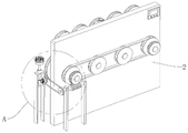
FIG. 10 is a schematic perspective view of the upright, the first driving wheel and the second driving wheel of the present invention;
in the figure: the device comprises a base 1, an air cylinder 10, a loop bar 11, a return spring 110, a connecting block 111, a tension spring 112, a processing table 12, a mounting seat 120, an L-shaped block 121, a buffer spring 122, a position sensor 123, a first driving wheel 13, a sliding block 130, a second driving wheel 131, a telescopic spring 132, a vertical plate 2, a controller 3, an unwinding mechanism 4, an unwinding roller 40, a first chain wheel 400, a second chain wheel 401, a chain 402, a synchronous wheel 403, a second belt 404, a driving component 41, a driving motor 410, a driving wheel 411, a driven wheel 412, a first belt 413, a straightening mechanism 5, a straightening component 50, a driving compression roller 500, a driven compression roller 501, a height adjusting component 51, a knob 510, a screw rod 511, a mounting plate 512, a conical indicating strip 513, a scale interval 514, a cleaning mechanism 6, a brush 60, a rotating component 61, a worm wheel 610, a worm 611, a first bevel gear 612, a second bevel gear 613, a belt 614, a third belt 615, the cutting mechanism 7, the cutter 70, the punching block 71, the sliding component 72, the rotary rod 720, the push rod 721, the mounting block 722 and the bump 723.
Detailed Description
The technical scheme of the invention is further explained by the specific implementation mode in combination with the attached drawings.
Wherein the showings are for the purpose of illustration only and are shown by way of illustration only and not in actual form, and are not to be construed as limiting the present patent; to better illustrate the embodiments of the present invention, some components of the drawings may be omitted, enlarged or reduced, and do not represent the size of an actual product.
Referring to fig. 1 to 10, the multifunctional cable cutting device includes a base 1 and a vertical plate 2, and further includes a controller 3, an unwinding mechanism 4, a straightening mechanism 5, a cleaning mechanism 6 and an undercutting mechanism 7, wherein the controller 3 is disposed on an outer wall of the vertical plate 2, the unwinding mechanism 4 is disposed on a top of the base 1, the unwinding mechanism 4 includes an unwinding roller 40 and a driving assembly 41, the straightening mechanism 5 is disposed between the unwinding mechanism 4 and the cleaning mechanism 6, the straightening mechanism 5 includes a straightening assembly 50 and a height adjusting assembly 51, the straightening assembly 50 is disposed on an outer wall of the vertical plate 2, the height adjusting assembly 51 is disposed on an outer wall of the vertical plate 2, the undercutting mechanism 7 is disposed on a top of the base 1, the cleaning mechanism 6 is disposed between the straightening mechanism 5 and the undercutting mechanism 7, the cleaning mechanism 6 includes a brush 60 and a rotating assembly 61, the rotating assembly 61 is disposed on a top of the base 1, the rotatable setting of brush 60 is at the top of base 1, and undercut mechanism 7 includes cutter 70, punching press piece 71 and sliding assembly 72, sliding assembly 72 establishes the top at base 1, punching press piece 71 establishes the top at cutter 70, cutter 70 slides and establishes the below at punching press piece 71, drive assembly 41 is electric connection with controller 3.
The driving assembly 41 comprises a driving motor 410, a driving wheel 411, a driven wheel 412 and a first belt 413, the top of the base 1 is symmetrically provided with two support plates, the unwinding roller 40 is rotatably arranged between the two support plates through a first rotating shaft, the driving motor 410 is fixedly arranged on the outer wall of one of the support plates, the driving wheel 411 is sleeved on the output end of the driving wheel, the driven wheel 412 is sleeved on one end of the first rotating shaft, the first belt 413 is sleeved between the driving wheel 411 and the driven wheel 412, the driving motor 410 is electrically connected with the controller 3, when cutting a cable, the cable in a roll shape is firstly wound on the outer wall of the winding roller, then the free end of the cable passes through the first driving wheel 13 and the second driving wheel 131 on one of the upright posts and is inserted between the driving compression roller 500 and the driven compression roller 501, and then the driving motor 410 is started, so as to drive the driving wheel 411 to rotate, because driving wheel 411 cup joints through first belt 413 with from driving wheel 412, because unreel roller 40 cup joints with first pivot again, first pivot cup joints with from driving wheel 412 to drive the cable on the wind-up roll and unreel.
The height adjusting assembly 51 comprises a knob 510, a screw rod 511 and a mounting plate 512, the mounting plate 512 is slidably arranged on the outer wall of the vertical plate 2, the screw rod 511 is rotatably arranged on the outer wall of the vertical plate 2, the screw rod 511 is in threaded connection with the mounting plate 512, the knob 510 is fixedly arranged at the top of the screw rod 511, one end of the mounting plate 512 is fixedly provided with a conical indicating strip 513, the outer wall of the vertical plate 2 is provided with a scale value 514, the conical indicating strip 513 faces the scale value 514, when cables with different thicknesses need to be cut, the screw rod 511 is driven to rotate by rotating the knob 510, the mounting plate 512 is in threaded connection with the mounting plate 512, the mounting plate 512 is slidably connected with the vertical plate 2, and each driven press roller 501 is hinged with the mounting plate 512, so that the driven press rollers 501 are driven to ascend, the distance between the driving press rollers 500 and the driven press rollers 501 is increased, and the thicker cables can pass through, the tapered indicator 513 slides on the scale 514 to display the rising distance of the driven rollers 501 in real time, thereby realizing accurate adjustment.
The straightening assembly 50 comprises a plurality of driving compression rollers 500 and a plurality of driven compression rollers 501, each driving compression roller 500 is rotatably arranged on the outer wall of the vertical plate 2 through a first hinge shaft, each driven compression roller 501 is hinged on the outer wall of the mounting plate 512, one end of the first hinge shaft, which is far away from the driving motor 410, is sleeved with a first chain wheel 400, a first hinge shaft, which is close to the first chain wheel 400, is sleeved with a second chain wheel 401, the first chain wheel 400 and the second chain wheel 401 are sleeved through a chain 402, one end of each first hinge shaft, which is far away from the driving compression rollers 500, is sleeved with a synchronizing wheel 403, a plurality of synchronizing wheels 403 are all sleeved through a second belt 404, when unreeling is carried out, as the first chain wheel 400 is sleeved with the first hinge shaft, the second chain wheel 401 is sleeved with one first hinge shaft, which is close to the first chain wheel 400, and as each first hinge shaft is inserted with one driving compression roller 500, every first articulated shaft is kept away from the one end of initiative compression roller 500 and is all overlapped and be designed synchronizing wheel 403, all cup joints through second belt 404 between a plurality of synchronizing wheel 403, and then drives a plurality of initiative compression roller 500 rotatory, with the cooperation of the driven compression roller 501 of a plurality of, straightens the cable, and in the straightening, carry the cable after will straightening to the one end that is close to processing platform 12.
The rotating assembly 61 comprises a worm wheel 610, a worm 611, a first bevel gear 612 and a second bevel gear 613, the worm wheel 610 is sleeved on one of the first hinge shafts close to the brush 60, the worm 611 is rotatably arranged at the side of the worm wheel 610 through the second hinge shaft, the worm wheel 610 and the worm 611 are in meshed connection, the top of the base 1 is fixedly provided with a first frame body, a third hinge shaft is inserted on the outer wall of the first frame body, belt wheels 614 are arranged on the third hinge shaft and the second hinge shaft, a third belt 615 is sleeved between the two belt wheels 614, the first bevel gear 612 is sleeved on the third hinge shaft, the top of the support frame is vertically provided with a second rotating shaft, the second bevel gear 613 is sleeved on the outer wall of the second rotating shaft, the first bevel gear 612 and the second bevel gear 613 are in meshed connection, the brush 60 is fixedly arranged on the top of the second rotating shaft, when the cable is straightened, the worm 611 is sleeved with one of the first hinge shafts close to the brush 60, the worm 611 is meshed with the worm wheel, so that the second hinge shaft is driven to rotate, the second hinge shaft and the third hinge shaft are both provided with belt wheels 614, the two belt wheels 614 are sleeved through a third belt 615, so that the third hinge shaft is driven to rotate, in addition, the first bevel gear 612 is sleeved with the third hinge shaft, the second bevel gear 613 is sleeved with the second rotating shaft, the first bevel gear 612 is meshed with the second bevel gear 613, the brush 60 is fixedly connected with the top of the second rotating shaft, so that the brush 60 is driven to rotate, impurities such as dust on the surface of the cable are cleaned, on one hand, the overall cleanliness of the cable is improved, on the other hand, the dust can be prevented from contacting with the cutter 70, the damage to the cutter 70 is reduced, and a protection function is achieved.
The sliding assembly 72 includes a rotating rod 720, a push rod 721 and an installation block 722, a second frame body is fixedly arranged on the top of the base 1, a first sliding slot is arranged on the top of the second frame body, the installation block 722 is fixedly arranged inside the first sliding slot through a bolt, the push rod 721 is slidably arranged on the top of the second frame body, the rotating rod 720 is hinged on the outer wall of the installation block 722 through a third rotating shaft, the other end of the rotating rod 720 is fixedly connected with the push rod 721 through an inserting rod, a plurality of inserting holes for inserting the inserting rods are equidistantly arranged on the push rod 721, a convex block 723 is fixedly arranged at the bottom of the rotating rod 720, a torsion spring is sleeved on the outer wall of the third rotating shaft, when a cable is continuously conveyed forwards through the processing table 12 and is abutted against the convex block 723, because the rotating rod 720 is hinged with the installation block 722, the convex block 723 is abutted under the action of the torsion spring to drive the rotating rod 720 to rotate, and because the other end of the rotating rod 720 is fixedly connected with the counterclockwise push rod 721 through the inserting rod, push rod 721 and second support body sliding connection, thereby it slides to the one end that is close to connecting block 111 to drive push rod 721, the torsional spring plays the effect that resets, automatic drive swing arm 720 resets after the cable realizes the cutting at every turn, because swing arm 720 position is unchangeable, therefore, the conflict distance of cable and lug 723 is unchangeable at every turn, thereby realize the fixed length cutting of cable, prevent the inequality that the artificial cutting caused, promote the cutting quality, simultaneously because swing arm 720 is detachable, therefore, can change its position that is located between first support body and push rod 721, thereby realize the length change of fixed length cutting, realize the fixed length cutting of different length promptly, satisfy the multiple requirement of cable cutting, the practicality and the flexibility of this equipment have further been promoted.
Fixed diaphragm that is equipped with on the one end outer wall that the second support body is close to the L template, the top of diaphragm is equipped with the guide arm, the cover is equipped with loop bar 11 on the first outer wall of guide arm, the cover is equipped with reset spring 110 on the lower half outer wall of guide arm, the fixed connecting block 111 that is equipped with in top of loop bar 11, connecting block 111 and the laminating of push rod 721, the fixed extension spring 112 that is equipped with between the outer wall of loop bar 11 and the top of second support body, slide to touching with connecting block 111 when the push rod 721 to the one end that is close to connecting block 111, push rod 721 contradicts connecting block 111, because connecting block 111 and loop bar 11 fixed connection, loop bar 11 rotates with the guide arm to be connected, thereby it is rotatory to drive connecting block 111 to the top one end that is close to the L shape piece, reset spring 110 finishes driving loop bar 11 and connecting block 111 on its outer wall at every turn of cutting, so that push down to L shape piece next time.
The top of base 1 is equipped with processing platform 12, the fixed mount pad 120 that is equipped with in top of processing platform 12, the top of processing platform 12 is seted up and is supplied cutter 70 undercut to dodge the groove, it is equipped with L type piece 121 to slide on the outer wall of mount pad 120, cutter 70 and L type piece 121 fixed connection, it is provided with two gag lever posts to be the symmetry between the top of L type piece and processing platform 12, all overlap on the outer wall of every gag lever post and be equipped with buffer spring 122, the fixed position sensor 123 that is equipped with in top of mount pad 120, position sensor 123 is connected with controller 3 electricity, when connecting block 111 is rotatory to the top one end that is close to the L type piece, position sensor 123 detects the arrival of connecting block 111, give controller 3 with signal transmission, mount pad 120 is being used for installing L type piece 121, L type piece 121 is used for installing cutter 70.
The working principle of the invention is as follows: when the cable is cut, firstly, the coiled cable is coiled on the outer wall of the winding roller, then the free end of the coiled cable penetrates through the first driving wheel 13 and the second driving wheel 131 on one of the stand columns and is inserted between the driving compression roller 500 and the driven compression roller 501, and then the driving motor 410 is started, so that the driving wheel 411 is driven to rotate, because the driving wheel 411 and the driven wheel 412 are sleeved through the first belt 413, and because the unwinding roller 40 is sleeved with the first rotating shaft, the first rotating shaft is sleeved with the driven wheel 412, so that the cable on the winding roller is driven to be unwound.
When unreeling, because first sprocket 400 and first pivot cup joint, second sprocket 401 cup joints with one of them first articulated shaft that is close to first sprocket 400, again because every first articulated shaft all pegs graft with a drive compression roller 500, every first articulated shaft is kept away from the one end of drive compression roller 500 and is all overlapped and is designed synchronizing wheel 403, all cup joint through second belt 404 between a plurality of synchronizing wheel 403, and then it is rotatory to drive a plurality of drive compression roller 500, cooperate with a plurality of driven compression roller 501, straighten the cable, and in the straightening, carry the cable after the straightening to the one end that is close to processing platform 12.
During cable straightening, the worm 611 is sleeved with one of the first hinge shafts close to the brush 60, and the worm 611 is meshed with the worm wheel, so that the second hinge shaft is driven to rotate, the second hinge shaft and the third hinge shaft are both provided with the belt wheels 614, the two belt wheels 614 are sleeved with each other through the third belt 615, so that the third hinge shaft is driven to rotate, in addition, the first bevel gear 612 is sleeved with the third hinge shaft, the second bevel gear 613 is sleeved with the second rotating shaft, the first bevel gear 612 is meshed with the second bevel gear 613, the brush 60 is fixedly connected with the top of the second rotating shaft, so that the brush 60 is driven to rotate, impurities such as dust on the surface of the cable are cleaned, on one hand, the overall cleanliness of the cable is improved, on the other hand, the dust can be prevented from contacting with the cutter 70, damage to the cutter 70 is reduced, and a protection function is achieved.
When the cable is continuously conveyed forwards through the processing table 12 to collide with the bump 723, because the rotating rod 720 is hinged with the mounting block 722, the bump 723 is pressed to rotate anticlockwise under the action of the torsion spring, and because the other end of the rotating rod 720 is fixedly connected with the push rod 721 through the inserted link, the push rod 721 is connected with the second frame body in a sliding manner, so as to drive the push rod 721 to slide towards one end close to the connecting block 111, the torsion spring plays a role in resetting, the rotating rod 720 is automatically driven to reset after the cable is cut every time, because the position of the rotating rod 720 is unchanged, the collision distance between the cable and the bump 723 is unchanged every time, thereby realizing the fixed-length cutting of the cable, preventing the unevenness caused by artificial cutting, improving the cutting quality, and because the rotating rod 720 is detachable, the position between the first frame body and the push rod 721 can be changed, thereby realizing the length change of the fixed-length cutting, realize the fixed length cutting of different length promptly, satisfy the multiple requirement of cable cutting, further promoted the practicality and the flexibility of this equipment.
When the push rod 721 slides to the one end that is close to connecting block 111 and touches with connecting block 111, the push rod 721 butts connecting block 111, because connecting block 111 and loop bar 11 fixed connection, loop bar 11 rotates with the guide arm to it is rotatory to drive connecting block 111 to the top one end that is close to the L-shaped piece, and reset spring 110 finishes at every cutting and drives loop bar 11 and the connecting block 111 on its outer wall to reset, so that push down to the L-shaped piece next time.
When connecting block 111 is rotatory to the top one end that is close to the L-shaped piece, position sensor 123 detects the arrival of connecting block 111, give controller 3 with signal transmission, after receiving the information that connecting block 111 arrived, start cylinder 10 through controller 3, thereby drive punching press piece 71 and descend, carry out the punching press to connecting block 111, and then push down L type piece 121 through connecting block 111, further drive cutter 70 on the L type piece 121 and push down, cut the cable, two buffer spring 122 end the automatic cutter 70 that drives of undercut at every turn and reset, so that cut next time.
When the cutting of the cable of different thicknesses is carried out to needs, through rotatory knob 510, thereby it is rotatory to drive lead screw 511, because lead screw 511 and mounting panel 512 threaded connection, mounting panel 512 and 2 sliding connection of riser, again because every driven compression roller 501 all is articulated with mounting panel 512, therefore it rises to drive the driven compression roller 501 of a plurality of, make the interval increase of a plurality of initiative compression roller 500 and driven compression roller 501, thereby satisfy thicker cable and pass, toper instruction strip 513 slides on scale value 514, the rise distance of the driven compression roller 501 of a plurality of is shown in real time, and then realize the accurate regulation.
Claims (4)
1. The utility model provides a multifunctional cable cutting equipment, includes base (1) and riser (2), its characterized in that: the automatic straightening device is characterized by further comprising a controller (3), an unreeling mechanism (4), a straightening mechanism (5), a cleaning mechanism (6) and a downward cutting mechanism (7), wherein the controller (3) is arranged on the outer wall of the vertical plate (2), the unreeling mechanism (4) is arranged at the top of the base (1), the unreeling mechanism (4) comprises an unreeling roller (40) and a driving assembly (41), the straightening mechanism (5) is arranged between the unreeling mechanism (4) and the cleaning mechanism (6), the straightening mechanism (5) comprises a straightening assembly (50) and a height adjusting assembly (51), the straightening assembly (50) is arranged on the outer wall of the vertical plate (2), the height adjusting assembly (51) is arranged on the outer wall of the vertical plate (2), the downward cutting mechanism (7) is arranged at the top of the base (1), the cleaning mechanism (6) is arranged between the straightening mechanism (5) and the downward cutting mechanism (7), the cleaning mechanism (6) comprises a brush (60) and a rotating assembly (61), the top at base (1) is established in rotating assembly (61), the rotatable setting of brush (60) is at the top of base (1), cuts mechanism (7) down and includes cutter (70), punching press piece (71) and sliding assembly (72), the top at base (1) is established in sliding assembly (72), punching press piece (71) is established in the top of cutter (70), cutter (70) slide and establish the below at punching press piece (71), drive assembly (41) and controller (3) are electric connection, drive assembly (41) include driving motor (410), action wheel (411), follow driving wheel (412) and first belt (413), the top of base (1) is the symmetry and is provided with two backup pads, unreeling roller (40) is through the rotatable setting of first pivot between two backup pads, and driving motor (410) are fixed to be established on the outer wall of one of them backup pad, the output end of the straightening assembly is sleeved with a driving wheel (411), a driven wheel (412) is sleeved with one end of a first rotating shaft, a first belt (413) is sleeved between the driving wheel (411) and the driven wheel (412), a driving motor (410) is electrically connected with a controller (3), the height adjusting assembly (51) comprises a knob (510), a screw rod (511) and a mounting plate (512), the mounting plate (512) is arranged on the outer wall of a vertical plate (2) in a sliding mode, the screw rod (511) is rotatably arranged on the outer wall of the vertical plate (2), the screw rod (511) is in threaded connection with the mounting plate (512), the knob (510) is fixedly arranged at the top of the screw rod (511), a conical indicating strip (513) is fixedly arranged at one end of the mounting plate (512), a scale value (514) is arranged on the outer wall of the vertical plate (2), the conical indicating strip (513) faces towards the scale value (514), the straightening assembly (50) comprises a plurality of driving compression rollers (500) and a plurality of driven compression rollers (501), each driving pressure roller (500) is rotatably arranged on the outer wall of the vertical plate (2) through a first hinge shaft, each driven pressure roller (501) is hinged to the outer wall of the mounting plate (512), one end, far away from the driving motor (410), of the first hinge shaft is sleeved with a first chain wheel (400), one first hinge shaft, close to the first chain wheel (400), is sleeved with a second chain wheel (401), the first chain wheel (400) and the second chain wheel (401) are sleeved through a chain (402), one end, far away from the driving pressure rollers (500), of each first hinge shaft is sleeved with a synchronizing wheel (403), a plurality of synchronizing wheels (403) are sleeved through a second belt (404), each rotating assembly (61) comprises a worm wheel (610), a worm (611), a first bevel gear (612) and a second bevel gear (613), the worm wheel (610) is sleeved on one first hinge shaft, close to the brush (60), the worm (611) is rotatably arranged at the side of the worm wheel (610) through a second hinge shaft, the worm wheel (610) is meshed with the worm (611), a first frame body is fixedly arranged at the top of the base (1), a third hinge shaft is inserted on the outer wall of the first frame body, belt wheels (614) are arranged on the third hinge shaft and the second hinge shaft, a third belt (615) is sleeved between the two belt wheels (614), a first bevel gear (612) is sleeved on the third hinge shaft, a second rotating shaft is vertically arranged at the top of the supporting frame, a second bevel gear (613) is sleeved on the outer wall of the second rotating shaft, the first bevel gear (612) is meshed with a second bevel gear (613), the brush (60) is fixedly arranged at the top of the second rotating shaft, the sliding component (72) comprises a rotary rod (720), a push rod (721) and a mounting block (722), the second frame body is fixedly arranged at the top of the base (1), first spout has been seted up at the top of second support body, the inside at first spout is established through the bolt fastening in installation piece (722), push rod (721) slide and establish the top at the second support body, swing arm (720) set up on the outer wall of installation piece (722) through the third pivot is articulated, the other end and push rod (721) of swing arm (720) pass through inserted bar fixed connection, equidistant a plurality of jack that can supply the inserted bar to peg graft that is provided with on push rod (721), the fixed lug (723) that is equipped with in bottom of swing arm (720), the cover is equipped with the torsional spring on the outer wall of third pivot, the fixed L template that is equipped with in top of base (1), the fixed cylinder (10) that is equipped with in top of L template, the output of cylinder (10) is vertical down, the output fixed connection of punching press piece (71) and cylinder (10), cylinder (10) are connected with controller (3) electricity.
2. A multifunctional cable cutting apparatus as claimed in claim 1, wherein: the fixed diaphragm that is equipped with on the one end outer wall that the second support body is close to the L template, the top of diaphragm is equipped with the guide arm, and the cover is equipped with loop bar (11) on the first outer wall of guide arm, and the cover is equipped with reset spring (110) on the lower half outer wall of guide arm, and the top of loop bar (11) is fixed and is equipped with connecting block (111), and connecting block (111) and push rod (721) laminate, fixedly between the outer wall of loop bar (11) and the top of second support body be equipped with extension spring (112).
3. A multifunctional cable cutting apparatus as claimed in claim 2, wherein: the top of base (1) is equipped with processing platform (12), the fixed mount pad (120) that is equipped with in top of processing platform (12), the groove of dodging that can supply cutter (70) undercut is seted up at the top of processing platform (12), it is equipped with L type piece (121) to slide on the outer wall of mount pad (120), cutter (70) and L type piece (121) fixed connection, it is the symmetry between the top of L type piece and processing platform (12) and is provided with two gag lever posts, all overlap on the outer wall of every gag lever post and be equipped with buffer spring (122), the fixed position sensor (123) that are equipped with in top of mount pad (120), position sensor (123) are connected with controller (3) electricity.
4. A multifunctional cable cutting apparatus as claimed in claim 3, wherein: the top both ends of base (1) are the symmetry and are provided with two stands, the top of every stand all is equipped with logical groove, the articulated first drive wheel (13) that is provided with in bottom that leads to the groove, the top of every stand all is the symmetry and is provided with two second spouts, the inside of every second spout all is equipped with slider (130), rotatable second drive wheel (131) that are provided with between two slider (130), all fixed expanding spring (132) that are equipped with between the inboard top of the top of every slider (130) and a second spout.
Priority Applications (1)
| Application Number | Priority Date | Filing Date | Title |
|---|---|---|---|
| CN202110586694.1A CN113178810B (en) | 2021-05-27 | 2021-05-27 | Multifunctional cable cutting equipment |
Applications Claiming Priority (1)
| Application Number | Priority Date | Filing Date | Title |
|---|---|---|---|
| CN202110586694.1A CN113178810B (en) | 2021-05-27 | 2021-05-27 | Multifunctional cable cutting equipment |
Publications (2)
| Publication Number | Publication Date |
|---|---|
| CN113178810A CN113178810A (en) | 2021-07-27 |
| CN113178810B true CN113178810B (en) | 2022-06-21 |
Family
ID=76927162
Family Applications (1)
| Application Number | Title | Priority Date | Filing Date |
|---|---|---|---|
| CN202110586694.1A Active CN113178810B (en) | 2021-05-27 | 2021-05-27 | Multifunctional cable cutting equipment |
Country Status (1)
| Country | Link |
|---|---|
| CN (1) | CN113178810B (en) |
Families Citing this family (2)
| Publication number | Priority date | Publication date | Assignee | Title |
|---|---|---|---|---|
| CN114054642B (en) * | 2021-11-10 | 2023-08-08 | 东莞市众晟强电子有限公司 | Equal-length cutting device for cable processing |
| CN114653910B (en) * | 2022-03-10 | 2023-02-10 | 江西台鑫钢铁有限公司 | Billet heating bypass hot conveying mechanism |
Family Cites Families (15)
| Publication number | Priority date | Publication date | Assignee | Title |
|---|---|---|---|---|
| KR100913612B1 (en) * | 2007-05-31 | 2009-08-26 | (주)티에이치엔 | Method for processing opposite end of a covered wire |
| JP2010082681A (en) * | 2008-10-02 | 2010-04-15 | Tosano Seisakusho:Kk | Straight line cutting machine |
| CN205967205U (en) * | 2016-08-10 | 2017-02-22 | 浙江好得电气有限公司 | Wiring device of cable and have this wiring device's wire stripping machine |
| CN206536087U (en) * | 2017-02-20 | 2017-10-03 | 三樱(东莞)汽车部件有限公司 | A kind of automatic tube cutting device |
| CN107962139A (en) * | 2017-11-28 | 2018-04-27 | 江苏胜达科技有限公司 | Aligning, cutting wire rod integrated device |
| CN208495658U (en) * | 2018-07-11 | 2019-02-15 | 深圳市六讯电子科技有限公司 | A kind of data line cutting device for processing convenient for controlling Cutting Length |
| CN111215686B (en) * | 2019-12-09 | 2021-05-25 | 湖南申亿五金标准件有限公司 | Pipe cutting equipment of equidistance propelling movement material for hardware processing |
| CN111618204B (en) * | 2020-01-08 | 2021-10-22 | 深圳市深鹏达电网科技有限公司 | Automatic cutting equipment for power cable and using method thereof |
| CN111151687A (en) * | 2020-03-09 | 2020-05-15 | 深圳市威顺源精密电子有限公司 | Metal wire feeding online cutting machine |
| CN111571615A (en) * | 2020-05-28 | 2020-08-25 | 汪彩红 | Intelligent robot for clearing obstacles of power equipment |
| CN111816373A (en) * | 2020-07-27 | 2020-10-23 | 梁波 | Flexible fire-resistant flame retarded cable processing cutting device |
| CN112354979B (en) * | 2020-10-19 | 2023-08-18 | 巢湖市鼎力铁塔有限公司 | Building site steel pipe surface cleaning equipment |
| CN112355174B (en) * | 2020-10-26 | 2023-03-31 | 太仓太标汽车部件有限公司 | Rapid forming device for precise special-shaped stud bolt and working method |
| CN112436365A (en) * | 2020-11-12 | 2021-03-02 | 朱昀 | Power cable sheath stripping device |
| CN112719141A (en) * | 2020-12-18 | 2021-04-30 | 安徽云飞芳植生物科技有限公司 | Machining is with saving waste recovery device for environmental protection |
-
2021
- 2021-05-27 CN CN202110586694.1A patent/CN113178810B/en active Active
Also Published As
| Publication number | Publication date |
|---|---|
| CN113178810A (en) | 2021-07-27 |
Similar Documents
| Publication | Publication Date | Title |
|---|---|---|
| CN113178810B (en) | Multifunctional cable cutting equipment | |
| CN109501435B (en) | Three-roller synchronous stripping machine | |
| CN218656397U (en) | Feeding structure of automatic punching machine for aluminum foil lunch box | |
| CN212704152U (en) | Portable cable cuts equipment for electric power engineering | |
| CN210475054U (en) | Shell metal sheet straightener is used in automatically controlled cabinet processing | |
| CN216711046U (en) | Synchronous lifting and winding device of metal slitting belt felt tensioner | |
| CN111250627A (en) | Efficient steel bar bending equipment in field of constructional engineering | |
| CN215666100U (en) | Production line for ultrathin steel wire rope core conveying belt | |
| CN210967202U (en) | Sheet cutting production equipment is used in production of mirror surface aluminum plate | |
| CN112247011B (en) | A assembly line for new forms of energy license plate is made | |
| CN212398562U (en) | Movable robot is used in welding | |
| CN209866975U (en) | Adjustable pipe mill | |
| CN108675035B (en) | Light object automatic cutting transmission device based on infrared monitoring | |
| CN114210743A (en) | Soft longitudinal shearing guide and guard equipment for cold-rolled sheet | |
| CN113275893A (en) | Assembled building board anti-bending correction device | |
| CN116460183B (en) | 90-degree bending hot-pressing equipment for display screen flat cable | |
| CN213802181U (en) | Deviation correcting device for coiled material industry | |
| CN219669415U (en) | Film laminating device for mobile phone glass cover plate production | |
| CN214686733U (en) | Optical fiber cable cutting device for communication engineering | |
| CN212530216U (en) | Film sticking device | |
| CN216369582U (en) | Elevator accessory production is with panel material unreeling frame | |
| CN114935300B (en) | Cable defect detection equipment based on cable geometry | |
| CN215749489U (en) | Die-cut forming device of insulating wheat pulling-on piece production | |
| CN216989275U (en) | Aluminum plate processing is with levelling machine convenient to use | |
| CN216004575U (en) | Rolling cutting device is used in sticky tape production |
Legal Events
| Date | Code | Title | Description |
|---|---|---|---|
| PB01 | Publication | ||
| PB01 | Publication | ||
| SE01 | Entry into force of request for substantive examination | ||
| SE01 | Entry into force of request for substantive examination | ||
| GR01 | Patent grant | ||
| GR01 | Patent grant |