CN1131732C - Apparatus and process for coating tablets - Google Patents
Apparatus and process for coating tablets Download PDFInfo
- Publication number
- CN1131732C CN1131732C CN99815283.8A CN99815283A CN1131732C CN 1131732 C CN1131732 C CN 1131732C CN 99815283 A CN99815283 A CN 99815283A CN 1131732 C CN1131732 C CN 1131732C
- Authority
- CN
- China
- Prior art keywords
- nozzle
- gas
- tablet
- base plate
- upwards
- Prior art date
- Legal status (The legal status is an assumption and is not a legal conclusion. Google has not performed a legal analysis and makes no representation as to the accuracy of the status listed.)
- Expired - Fee Related
Links
- 238000000576 coating method Methods 0.000 title claims abstract description 48
- 239000011248 coating agent Substances 0.000 title claims abstract description 44
- 238000000034 method Methods 0.000 title claims abstract description 35
- 230000008569 process Effects 0.000 title claims abstract description 22
- 239000012530 fluid Substances 0.000 claims abstract description 39
- 239000007921 spray Substances 0.000 claims abstract description 39
- 230000000694 effects Effects 0.000 claims abstract description 10
- 238000005507 spraying Methods 0.000 claims description 19
- 239000007788 liquid Substances 0.000 claims description 17
- 230000005764 inhibitory process Effects 0.000 claims description 16
- 230000000873 masking effect Effects 0.000 claims description 15
- 239000003595 mist Substances 0.000 claims description 12
- 230000015572 biosynthetic process Effects 0.000 claims description 5
- 230000008859 change Effects 0.000 claims description 4
- 239000000725 suspension Substances 0.000 claims description 3
- 230000002401 inhibitory effect Effects 0.000 claims description 2
- 230000000452 restraining effect Effects 0.000 claims description 2
- 238000005755 formation reaction Methods 0.000 claims 2
- 238000005192 partition Methods 0.000 abstract 1
- 239000007789 gas Substances 0.000 description 41
- 239000002245 particle Substances 0.000 description 16
- 230000033001 locomotion Effects 0.000 description 7
- 238000005516 engineering process Methods 0.000 description 6
- 238000000889 atomisation Methods 0.000 description 4
- 239000003814 drug Substances 0.000 description 3
- 238000001035 drying Methods 0.000 description 3
- 238000005243 fluidization Methods 0.000 description 3
- 230000006872 improvement Effects 0.000 description 3
- 238000004519 manufacturing process Methods 0.000 description 3
- 239000006187 pill Substances 0.000 description 3
- 239000004480 active ingredient Substances 0.000 description 2
- 239000011247 coating layer Substances 0.000 description 2
- 230000008021 deposition Effects 0.000 description 2
- 238000001514 detection method Methods 0.000 description 2
- 238000009826 distribution Methods 0.000 description 2
- 239000000428 dust Substances 0.000 description 2
- 239000000463 material Substances 0.000 description 2
- 230000036961 partial effect Effects 0.000 description 2
- 238000005096 rolling process Methods 0.000 description 2
- 239000002700 tablet coating Substances 0.000 description 2
- 238000009492 tablet coating Methods 0.000 description 2
- 206010000234 Abortion spontaneous Diseases 0.000 description 1
- 230000009471 action Effects 0.000 description 1
- 230000002411 adverse Effects 0.000 description 1
- 239000003905 agrochemical Substances 0.000 description 1
- 238000007605 air drying Methods 0.000 description 1
- 239000007864 aqueous solution Substances 0.000 description 1
- QVGXLLKOCUKJST-UHFFFAOYSA-N atomic oxygen Chemical compound [O] QVGXLLKOCUKJST-UHFFFAOYSA-N 0.000 description 1
- 230000008901 benefit Effects 0.000 description 1
- 230000005540 biological transmission Effects 0.000 description 1
- 239000003054 catalyst Substances 0.000 description 1
- 239000001913 cellulose Substances 0.000 description 1
- 229920002678 cellulose Polymers 0.000 description 1
- 230000019771 cognition Effects 0.000 description 1
- 238000010960 commercial process Methods 0.000 description 1
- 239000012141 concentrate Substances 0.000 description 1
- 238000010276 construction Methods 0.000 description 1
- 238000013270 controlled release Methods 0.000 description 1
- 239000013078 crystal Substances 0.000 description 1
- 230000002950 deficient Effects 0.000 description 1
- 230000037213 diet Effects 0.000 description 1
- 235000005911 diet Nutrition 0.000 description 1
- 239000003337 fertilizer Substances 0.000 description 1
- 238000002309 gasification Methods 0.000 description 1
- 239000008187 granular material Substances 0.000 description 1
- 229920003088 hydroxypropyl methyl cellulose Polymers 0.000 description 1
- 238000009434 installation Methods 0.000 description 1
- 230000002045 lasting effect Effects 0.000 description 1
- 239000010410 layer Substances 0.000 description 1
- 125000002496 methyl group Chemical group [H]C([H])([H])* 0.000 description 1
- 208000015994 miscarriage Diseases 0.000 description 1
- 238000012544 monitoring process Methods 0.000 description 1
- 238000002663 nebulization Methods 0.000 description 1
- 239000001301 oxygen Substances 0.000 description 1
- 229910052760 oxygen Inorganic materials 0.000 description 1
- 230000000149 penetrating effect Effects 0.000 description 1
- 230000002035 prolonged effect Effects 0.000 description 1
- 230000002829 reductive effect Effects 0.000 description 1
- 239000000243 solution Substances 0.000 description 1
- 208000000995 spontaneous abortion Diseases 0.000 description 1
- 230000003068 static effect Effects 0.000 description 1
- 239000000126 substance Substances 0.000 description 1
- 238000009834 vaporization Methods 0.000 description 1
- 230000008016 vaporization Effects 0.000 description 1
- XLYOFNOQVPJJNP-UHFFFAOYSA-N water Substances O XLYOFNOQVPJJNP-UHFFFAOYSA-N 0.000 description 1
Images

Classifications
-
- B—PERFORMING OPERATIONS; TRANSPORTING
- B05—SPRAYING OR ATOMISING IN GENERAL; APPLYING FLUENT MATERIALS TO SURFACES, IN GENERAL
- B05B—SPRAYING APPARATUS; ATOMISING APPARATUS; NOZZLES
- B05B13/00—Machines or plants for applying liquids or other fluent materials to surfaces of objects or other work by spraying, not covered by groups B05B1/00 - B05B11/00
- B05B13/02—Means for supporting work; Arrangement or mounting of spray heads; Adaptation or arrangement of means for feeding work
- B05B13/0221—Means for supporting work; Arrangement or mounting of spray heads; Adaptation or arrangement of means for feeding work characterised by the means for moving or conveying the objects or other work, e.g. conveyor belts
- B05B13/025—Means for supporting work; Arrangement or mounting of spray heads; Adaptation or arrangement of means for feeding work characterised by the means for moving or conveying the objects or other work, e.g. conveyor belts the objects or work being present in bulk
-
- B—PERFORMING OPERATIONS; TRANSPORTING
- B01—PHYSICAL OR CHEMICAL PROCESSES OR APPARATUS IN GENERAL
- B01J—CHEMICAL OR PHYSICAL PROCESSES, e.g. CATALYSIS OR COLLOID CHEMISTRY; THEIR RELEVANT APPARATUS
- B01J2/00—Processes or devices for granulating materials, e.g. fertilisers in general; Rendering particulate materials free flowing in general, e.g. making them hydrophobic
- B01J2/006—Coating of the granules without description of the process or the device by which the granules are obtained
-
- Y—GENERAL TAGGING OF NEW TECHNOLOGICAL DEVELOPMENTS; GENERAL TAGGING OF CROSS-SECTIONAL TECHNOLOGIES SPANNING OVER SEVERAL SECTIONS OF THE IPC; TECHNICAL SUBJECTS COVERED BY FORMER USPC CROSS-REFERENCE ART COLLECTIONS [XRACs] AND DIGESTS
- Y10—TECHNICAL SUBJECTS COVERED BY FORMER USPC
- Y10S—TECHNICAL SUBJECTS COVERED BY FORMER USPC CROSS-REFERENCE ART COLLECTIONS [XRACs] AND DIGESTS
- Y10S118/00—Coating apparatus
- Y10S118/05—Fluidized bed
Abstract
A non-fluidized bed apparatus for coating tablets has a base plate (3) of which a portion (6) of the upper surface is inclined towards an upward directed two-fluid or three-fluid nozzle (5). Ducts (7) through the base plate around the nozzle produce jets of process gas in a direction intersecting an imaginary centre line of the spray produced by the nozzle. Atomizing gas from the nozzle is muffled shortly after it has left the nozzle to decrease the upward scattering effect of said gas on the tablets being coated. No partition is used for separating upward and downward flow of tablets during the coating process. In the coating process the amount of atomizing gas supplied to the nozzle is limited to reduce the tablet scattering effect of said gas.
Description
Invention field
The present invention relates to the coating of tablet.Wherein term " tablet " is used for wide significance, not only comprises real tablet in pharmaceutical industries, and comprises pill and wafer, and also comprise pill and particle in chemical fertilizer and agrochemical industry.
Therefore, the invention is not restricted to any specific industrial scale, be in the coating aspect of about 2mm to 50mm, the especially any object type in 3mm to 25mm scope certainly and can be applicable to average particle size particle size.
In other industrial scale of outside above-mentioned industry some, such as in purified industrial, diet and food industry and catalyst manufacturing industry, the coating operation is important equally.
Coating can be applicable to several purposes; for example to obtain desirable color or other vision enhancement; obtain continue or the opposite controlled release of active ingredient, for the protection tablet is avoided the intrusion of the humidity that causes because of environment and oxygen and prevented that tablet dust in processing procedure from forming.
Background of invention
The coating of most dose of sheet still utilize and in nearest 50 years used same quadrat method finish, and in painted groove, apply, although this device has important disadvantages.
These shortcomings are because in this groove, the side in each only these tablet two surfaces is exposed to the spraying of masking liquid.This device also has the inlet temperature of dry gas must be lower than the shortcoming of the maximum allowable temperature of product.This makes the evaporability of process gas descend, and forces spray rate to reduce, and the processing time is prolonged.In addition, need to use extremely moderate spraying rate, to prevent tablet owing to coating is pasted together, this fact has also reduced disposal ability.
Owing to there are these shortcomings relevant with painted groove, proposed some in order to coating particle material or wisp, such as the process of granula, pill, crystal grain.
Initial improvement is to adopt the fluid bed that suspends and produce.When being sprayed to air stream from the top adverse current, masking liquid acts on the product.Compare with painted groove, because the drying of fluidization air is renderd a service, its drying capacity has improved.Yet the inlet temperature of drying/fluidization air is subjected to the highest restriction of accepting temperature of product.
For improving the efficient of coating, granting the United States Patent (USP) NO.2 of (Wurster), suggestion produces one dry and suspension air turbulence in 648,609, its method be below this air turbulence being directed to the guiding principle that small pieces to be coated with cross before, make its through the pipeline in rotating disk.The purpose of utilizing turbulent air to flow is former to be to make small pieces obtain the effect of rolling, and makes the coating on it more even.Utilize masking liquid backward-acting this technology, can make dry air that higher inlet temperature is arranged in air stream, but because the contact between them during the small pieces tumbling motion, it handles difficulty more.In addition, be not enough to guarantee that by rolling of dry air turbulent flow generation masking liquid is sprayed at evenly distribution on each particle all surface.
And the relevant technology of waiting to be coated with the correct fluidisation of particle except in pharmaceuticals industry, is unsuitable for the small pieces of common size, because for given size and dimension, they can not be fluidized easily.Therefore, fluid bed is modified as so-called penetrating and annotates bed.In this structure, the eyelet of the plant air in this bottom all concentrates on one or more positions, and therefore, the plant air at these positions has enough speed and carries these small pieces with pneumatic mode.These nozzles are placed in the bottom of fluid bed, in the place same with these eyelets.At this moment, with masking liquid along and these small pieces identical direction of moving, i.e. downbeam coating.Because plant air enters the position of having settled atomizer aperture, thereby makes product, spray droplet and dry air move along equidirectional entirely, and therefore, heat and quality transmission are efficiently.This structural change also allows inlet temperature to be higher than the highest temperature of accepting of product, because heat of vaporization has cooled off product.Though this structure is more effective than previous structure, its place capacity is comparatively limited.The thickness of this gas producing formation is restricted, because must have minimum distance between these nozzles, to avoid interference.At the United States Patent (USP) NO.4 that grants Honda etc., the equipment of this structure has been described in 749,595.
Grant the United States Patent (USP) NO.5 of H ü ttlin, 145,650 also disclose a kind of fluid unit with some nozzles.Though its range of application is illustrated as and comprises the small pieces coating, yet these equipment intend being suitable for most handling and assembling smaller particles.Exquisite with frangible small pieces owing in fluid bed, continue over a long time to stop to tend to be damaged.
Grant the United States Patent (USP) NO.3 of Wurster, 253,944 disclose a kind of particle that will apply that makes stands to circulate.Replace fluid bed granulate motion random characteristic, a part of particle upwards flows, and sprayed simultaneously, and remaining particle flows downward.Should flow forms through hothouse bottom each several part by and moving air dry with the varying strength guiding, for example by means of hole and other eyelet of being distributed in certain pattern in the described bottom.Yet, proved already that the flowing downward of the particle that upwards flows and be dried of the particle of being sprayed was difficult for keeping separately, and be in contact with one another obvious this technical process that hindered between described two strands of grain flows.
Obtain the further improvement of coating technology by means of adopting a pipe or next door around the eyelet that enters and dispose the nozzle place at plant air.At the United States Patent (USP) NO.3 that invests people such as Wurster, the example of this equipment has been described in 241,520.Solved the subject matter of spray bed as the pipe in next door:, therefore can increase gas producing formation, and when in same housing, more nozzle being arranged, just solve the problem of phase mutual interference because this pipe allows freedom by being coated with product.This device credentials is very suitable for applying less object, but it is unsuitable for applying small pieces.This is because the free-falling speed of small pieces is higher, and in order to carry these small pieces with pneumatic mode, this plant air speed must must be higher than this free-falling speed.Yet this speed Gao Dechang can damage small pieces, and this depends on the intensity of these small pieces.
Another shortcoming of this equipment is to form to assemble when adopting thick coating solution.The deposition that also forms coating material on the surface of this pipe is a common problem, and the utilization of plant air drying capacity is not enough simultaneously.And in this structure, the serious problems of being partial to high scale are intrinsic.
Basically solved this rendezvous problem by means of the new equipment described in the WO 95/20432 (Aeromatic-Fielder AG), wherein, plant air had produced an eddy motion before reaching this equipment bay, and this plant air is just in time guided to around the nozzle that direction makes progress.Though this equipment has had tangible improvement, and can form more uniform quality coating, yet it not too is suitable for the large scale tablet, and is suitable for less object than miscellaneous equipment.
This part is because object to be coated with must be in the rotation when being sprayed by spray coating liquor point.
In the equipment described in the above-mentioned WO 95/20432, wait to be coated with particle and give birth to suitable rotation by the miscarriage of the shear in the plant air.Yet this method is unsuitable for the object of tablet size.
Therefore, when this object is bigger tablet, just need a kind of can making treat that coated object produces the new technology and the new equipment of desired such fast rotation.
And the development of tablet press machine and other manufacturing equipment has comprised significantly improving of its production capacity, therefore, needs the same raising of coated technique and capacity of equipment.
In addition, particularly in pharmaceuticals industry, more and more need to be suitable for making the technology of extremely exquisite coating.This means that remaining processed continuously all tablets in a collection of or a pile must receive essentially identical predetermined coating content, and this tittle must form uniform film of thickness or coating on all surface of each tablet.When the purpose of coating is the release that will continue from the tablet acquisition medicament of accepting to apply, or when coating itself comprised active ingredient, this was very important.
For generating laminated coating, also need a kind of above-mentioned exquisite coating.
Proved already such as above-mentioned United States Patent (USP) 3,241,520 and the embodiment of WO 95/20432 in the existence in next door of the pipe that adopted for the tablet coating, not only comprised the variety of problems that tablet wears away and formation viscosity deposits on it, and owing to adopt the structure in next door, the outside of next door keeps a thick-layer to treat coated object, requires product that the one long time of staying was arranged, and causes generation power low and to the lasting mechanical stress of the length of tablet.
Summary of the invention
The present invention is based on such approval, it is the above-mentioned shortcoming that it can avoid prior art processes, by adopting special pneumatic means to guide and controlling the motion of waiting to be coated with tablet, thereby saved next door used in the prior art, and, satisfied the requirement of stipulating in the tablet coated technique by controlling by the device that does not adopt so far in this technology and guiding the masking liquid spraying.
Described special pneumatic means comprises one input air-flow, and purpose is the glide path that influences this spray air after spray air applies its nebulization, to reduce its castering action that makes progress.Described influence is known as " inhibition " in this paper and appending claims.
Therefore, the present invention relates to a kind of un-fluidized-bed, in a housing, have at least one coating station, comprise a base plate that is shaped on eyelet, a two-fluid nozzle that is directed upwards towards along the center is arranged on this base plate in order to coating tablets; Described nozzle is provided the device of masking liquid; Produce the device of updraft with eyelet on base plate, wherein the upper surface of base plate tilts to nozzle.
This apparatus features is that the eyelet that passes base plate is that some are arranged in the pipeline around the nozzle, and described pipeline imaginary extends upward the imagining center line that part follows the mist that produced by nozzle to annotate and intersect; This device comprises also that spray gas is left and suppresses this spray gas to reduce the device of described gas to the effect of upwards scattering that is coated with tablet with pneumatic mode very soon behind the nozzle; And be subjected to this spraying and be not coated with the next door of tablet from the zone of the base plate top of the airflow influence of nozzle, restraining device and eyelet.
The device of pneumatic inhibition spray gas is considered to be suitable for most this purposes at present, and by means of it, can obtain the most practical experience, comprise the outlet of surrounding this two-fluid nozzle and producing the gas supply device that rotates up air-flow, it obtains the upwards spraying air-flow of distribution from this two-fluid nozzle, depart from and change described air-flow, make it change the vortex flow of broad into, had the effect that minimizing is upwards scattered being coated with tablet.
When the annular cavity type that gas is surround this nozzle when the outlet of described gas supply device flows out, can obtain very satisfied effect.Adopt this embodiment, forcing upwards, vortex inhibition gas stream converges with the spraying gasification.
Yet, also can utilize other measure to reach the inhibition of spray gas.Though made three liquid nozzles so far, so that in spraying area, obtain desirable gaseous environment, yet perhaps can revise three fluid nozzles like this, make the airflow direction in the top outskirt of nozzle partly tangent with the spray gas direction.Like this, the present invention also comprises some embodiments like this, and wherein, the device of pneumatic inhibition spray gas comprises a curtain that surrounds this two-fluid nozzle.This means and in fact adopted one three fluid nozzle.Therefore, term " two-fluid nozzle " is used as in this paper and appended claims and not only really comprises the two-fluid nozzle, and comprises the central part of three fluid nozzles, promptly carries the position of atomized liquid and spray gas.
In contrast, the advantage of above-mentioned embodiment is that the inhibition of importing through those pipelines is to supply from identical pressure chamber with handling air, therefore need not at work to regulate.
The preferential embodiment of other of apparatus of the present invention is illustrated together with following the description of the drawings.
The present invention also comprises a kind of process that is suitable for coating tablets, the making progress of masking liquid of utilizing above-mentioned device to make these tablets stand to be produced by a two-fluid nozzle sprayed, the characteristics of this method are before producing above-mentioned spraying, the off-centre bump that the upwards gas that intersects by means of the imagining center line with described mist post sprays makes these tablet rotations.Meanwhile and subsequently, the lead middle position of this two-fluid nozzle of the tablet that the above-mentioned gas jet flow will rotated is to increase the quantity of the suspension tablet that this mist of contact annotates; This two-fluid nozzle is provided with atomization gas, this atomization gas scale of construction is adjusted to less than meeting after slowing down through inhibition gas the gas flow that looses in these tablets are in away from the dry section of masking liquid droplet spraying.And the effect that tablet is upwards scattered of this spray gas weakens because of the pneumatic inhibitory action directly over this nozzle.
The preferential embodiment of this method further illustrates it together with following the description of the drawings.
The accompanying drawing summary
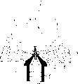
Fig. 1 is the vertical sectional view of applying device embodiment of the present invention;
Fig. 2 is the cutaway view that is similar to applying device embodiment central part of the present invention embodiment illustrated in fig. 1, has also represented to be coated with flowing of tablet;
The partial vertical sectional view of the base plate that Fig. 3 is in the embodiment of the invention shown in Fig. 1 and 2 to be adopted;
The base plate of Fig. 3 that the simple expression of Fig. 4 is seen certainly below,
Fig. 5 is the simple vertical sectional view with apparatus of the present invention embodiment of an above treating stations.
Preferential embodiment describes in detail
In applying device shown in Figure 1, a funnel-shaped piece 1 surrounds coating region 2.As shown in the figure, in this preferential embodiment, the inwall of the bottom of part 1 is just slightly tapered, or or even vertical
Below district 2, be base plate 3.
See that as the clearest from Fig. 3 and 4 important feature of the present invention is that the considerable part of being inserted by part (1) at least at base plate (3) upper surface position forms an inclined plane (6), the pointed end inclination of nozzle (5) that it is interior with respect to hole (4).Surface 6 gradient with respect to the horizontal plane is preferably 5 °-20 °, and 10 °-25 ° better.The position on this plate next-door neighbour 4 tops, hole with the nozzle top tip part, can project upwards (not shown), a little to avoid the deposition of dust in this district.
Another important characteristic of the present invention is that the pipeline 7 that passes base plate 3 is set.
In the preferential embodiment shown in these figure, these pipelines are all perpendicular to this inclined plane 6.Yet their direction can depart from the direction perpendicular to surface 6 slightly; For example, they can be not as seen in these figures so vertical, and in the case, the gradient on surface 6 can be slightly less than these pipelines perpendicular to the perpendicularity under surperficial 6 situations.
In addition, also pipeline 7 is arranged like this, the imaginary imaginary vertical center line that extends upward portion and hole 4 is intersected, this vertical center line also is the imagining center line of being annotated by the mist that nozzle 5 produces.
The diameter of these pipelines is generally 1-
 Mm, their length is not less than 3 times of diameter.
These pipelines can have different diameters, to produce the jet flow of varying strength.Like this, near the pipeline of nozzle 5 usually than being narrow from nozzle pipeline far away.
Distance between the pipeline 7 is maximum sized 0.2 to 1.5 times of tablet according to waiting that the size that is coated with tablet chooses.
Slightly the gross area of the pipeline 7 of large outlet 14 areas is as mentioned below, generally accounts for the 3-6% of the horizontal area on inclined plane 6, preferably about 4%.
On the lower surface of base plate 3, pipeline 7 has infundibulate end 8, to obtain the desirable flow pattern that flows through pipeline 7.
The below of base plate 3 is pressure chambers 9, in order to provide through the dry air of pipeline 7 with in order to the inhibition air of control from the spray air stream of two-fluid nozzle, also will describe in detail below.
Air is guided to this pressure chamber through pipe 10.
This pressure chamber can comprise more than one next door (not shown), thereby can suppress device (all grooves as mentioned below 13) air supply of gas with various pressure to each group pipeline 7 and/or introducing.
This two-fluid nozzle 5 receives masking liquid through conduit 11, receives spray air (Fig. 1) through pipe 12.
Clear see that from Fig. 2,3 and 4 be provided with groove 13 in order to the upwards awl wall of taper in the hole 4 that holds two-fluid nozzle 5 tops, when nozzle 5 installation in position, this groove constitutes the pipeline (Fig. 2) that passes to the outlet 14 of surrounding the nozzle top from pressure chamber 9.These grooves (13) and outlet (14) constitute the device (13,14) that suppresses this spray gas with pneumatic mode, soon, have weakened the upwards peptizaiton of spray gas to coated tablet after spray gas is left nozzle.The described embodiment of described this device has 6 such grooves (Fig. 4).These become arranged tangential with nozzle, and for this reason, the air that is passed to outlet 14 from pressure chamber through described groove is as leaving around the upwards vortex flow of enclosing nozzle.
Further specify the operation of this device with reference to Fig. 2, this figure has represented that also the tablet in the coated technique process flows.
By means of the process that is applied to described device of the present invention, the tablet that is coated with obtains high speed rotary motion before reaching the masking liquid spraying, simultaneously, avoided the tablet flow point being loose, for this reason, in spraying area, can make tablet keep concentrating of height from the spray air of two-fluid nozzle.
As can see from Figure 2, how The above results obtains, and the figure shows the periphery that tablet drops on base plate 3 downwards.Before the described plate of contact, owing to be inhaled into the influence of the air stream in the tablet of nozzle top, be subjected to simultaneously from the influence of pressure chamber 9 through the gas jet of pipeline 7 generations, these tablets obtain radially inwardly motion.Yet the main influence of these gas jets is to make these tablets produce a rapid circular movement before they reach the spraying of nozzle 5.The gas jet that sprays into through these pipelines has the speed of 80-180 meter per second, is preferably the 100-150 meter per second.
If do not take special measure to weaken the effect of scattering of the spray air of two-fluid nozzle, then these tablets can upwards be blown to suitable height, therefore, can be scattered, and this means that only the spray coating liquor cognition of fraction deposits on the surface of these tablets.In addition, this powerful mobile meeting damages these particles, and increases its wearing and tearing.
This process comprises two measures of avoiding above-mentioned defective.First drops to the spray air amount to be less than and is slowing down the back air capacity that tablet can be scattered of gas by inhibition.This means mist beam size than being generally used for the big of fluid nozzle, but because the size of tablet, this is unessential with regard to the quality of final coating.
The second, spray gas stream is suppressed by the inhibition gas of guiding to outlet 14 through groove 13.In described embodiment, suppress gas and leave outlet 14 with the speed that is approximately identical to one of pipeline 7 jet flows of supplying with by same pressure chamber 9.Yet when pressure chamber had more next door, it may regulate the gas flows that suppress gas flow and independently introduce through pipeline 7.This inhibition gas has produced one vortex flow, and it influences the spray air stream of nozzle rapidly.Therefore, last-mentioned spray air stream also becomes vortex, the result, and upward velocity component, thereby the hoisting power step-down of tablet, and the size variable that mist is annotated gets roomy a little.
This means that the particle that is rotating that 3 inclined surfaces move along the bottom surface is reaching the lifting that only obtains appropriateness when this mist is annotated.
This means that the rotation particle that passes through along base plate 3 inclined surfaces is reaching the lifting effect that only obtains appropriateness when this mist is annotated, their time of staying in the district that is subjected to a mist notes bump then prolong relatively.
Replace two-fluid or three fluid nozzles, another low-momentum sprayer unit as also being the static or the ultrasonic atomization device of low-momentum sprayer unit, can be considered to be applied in apparatus of the present invention and the method.
Apparatus and method of the present invention can be applicable to batch (-type) and continuous tablet coating.
The device of these two kinds of patterns can comprise one or more coatings station.When adopting more than one coating station, they both can be used as parallel system's independent operation, also can be chained together.
As shown in Figure 5, the coating station can be separated by wall 15, and when tablet was promoted by spray stream, they were arbitrarily by wall 15.
Being coated with another passage controlled constant or adjustable tumbling by this device that is coated with the tablet at station of standing from one also can obtain.
For continued operation, device of the present invention can comprise that usually 5 of the bunchiness downlink connection are coated with the station and control by the electrolytic cell that respectively is coated with the station from the passage at the next one station of standing.About 3,000 tablets of the coating ability of this multistation device/minute.If adopt the water-based masking liquid will obtain the coating of 20-30 μ m.Each tablet is by about 10 seconds of the total processing time at all 5 stations.
In this electrolytic cell at coating station, can use the coating of different components so that these tablets in only stroke of coated station electrolytic cell in the acquisition laminated coating.
The every nozzle of tablet quantity that is applied simultaneously is less than 500.
In commerce is used, device of the present invention is provided with naturally according to coming automatic apparatus operating by signal continuous or that each parameter of cycle monitoring obtains, these parameters such as gas or the flow or the temperature of the tablet that inputs or outputs of this device certainly, perhaps for conspicuous some other parameter of insider.
Further specify the present invention by means of following example.Example
In device shown in Figure 1, finish coat operations.
This device size is such, and the horizontal diameter that makes inclined surface 6 is 40mm.
This waits to be coated with tablet for circular, has following size:
Diameter 7.0mm
Height 4.5mm
Surface area 6.6 * 10
-5M
2
The weight of each tablet is 0.164 gram, and the tablet quantity in this batch is 200, suitable 32 gram gross weights.
Masking liquid is the Opadry of 20% percentage by weight
The YS-1-7003 aqueous solution, it be a kind of be based coating with methyl hydroxyprolyl-cellulose (hydroxypropyl methyl cellulose).
Surrounding environment:
19 ℃ of temperature
Relative humidity 64%
Be input to the gas feed temperature 108% of pressure chamber
Be input to 0.00684 meter of the flow of process gas dose rate of pressure chamber 9
3/ second
Through speed 128 meter per seconds of pipeline 7 with the process gas of outlet 14
Atomisation pressure 2.5 crust
Masking liquid spraying rate 8.25 Grams Per Minutes
40 seconds processing times
42 microns of coating layer thicknesses
Should to stand various checks and detection by the final tablet that applies.By these checks and detection, can see these tablet not damageds, and to assess this coating layer thickness be extremely uniformly and high-quality.
Utilize similar equipment and method of the present invention to finish several products in addition, the gained result shows the speed that the present invention can not only make the coating of each tablet adopt any commercial applying device to reach faster than the result, and has proved already that coating that apparatus of the present invention can make tablet was too exquisite or fragile so that can not apply with known commercial process method or equipment.
Claims (19)
1. un-fluidized-bed device in order to coating tablets, in a housing, has at least one coating station, comprise a base plate that is installed with eyelet, upwards be orientated two-fluid nozzle (5) at this base plate center, described nozzle is provided the device (11) of masking liquid, provide the device (12) of spray gas and the eyelet on base plate (3) that the upwards device (9) of gas stream is provided to nozzle, the upper surface of base plate (6) tilts with respect to nozzle, the eyelet that it is characterized in that passing base plate is that some are arranged in the pipeline around the nozzle, and the imaginary portion of extending upward of described pipeline is with being intersected by the imagining center line that the mist that nozzle produces is annotated; This device also has after spray gas is left nozzle at once and suppresses spray gas to reduce described gas to being coated with the device (13,14) that upwards scatters and act on of tablet with pneumatic mode; Base plate (3) upper area that influenced by the gas stream of nozzle spraying and gas stream and restraining device (13,14) and pipeline (7) has adheringly, can make the tablet of flowing through therebetween flow coated.
2. device as claimed in claim 1, it is characterized in that the device that suppresses spray gas with pneumatic mode comprises the outlet (14) that some surround two-fluid nozzle (5) and produce the gas supply device that rotates up air-flow, this rotates up air-flow and the spray gas stream intersection of spreading from making progress of two-fluid nozzle, to reduce its upward velocity, and depart from its direction, thereby make it change the vortex flow of broad into.
3. device as claimed in claim 2 is characterized in that described gas supply device is some grooves (13) in the base plate (3), and also provides the pressure chamber (9) of gas to be communicated with to the described pipeline (7) in the base plate.
4. device as claimed in claim 2 is characterized in that described source of the gas exports (14) formation and surrounds the chamber that the annular of this nozzle (5) is open upwards.
5. device as claimed in claim 1, thus the device that it is characterized in that pneumatic inhibition spray gas comprises that is surrounded the curtain that the two-fluid nozzle constitutes three fluid nozzles.
6. device as claimed in claim 1 is characterized in that base plate gradient with respect to the horizontal plane is 5 °-20 °, and the concentric pipeline (7) around the nozzle is perpendicular to the inclined upper surface of base plate.
7. device as claimed in claim 1 is characterized in that base plate gradient with respect to the horizontal plane is 10 °-15 °, and the concentric pipeline (7) around the nozzle is perpendicular to the inclined upper surface of base plate.
8. device as claimed in claim 6 is characterized in that the distance between pipeline (7) is chosen according to the size that is coated with tablet, is maximum sized 0.2 to 1.5 times of tablet.
9. device as claimed in claim 1, it is characterized in that one vertically or a little upwards the awl wall of expansion around the angled section of plate upper surface, extend, this wall is changing direction from base plate one distance, to form the more cone (1) of expansion.
10. device as claimed in claim 1, it is characterized in that having a plurality of coatings station, they are by being arranged on the base plate or separating each other near the local dividing wall (15) of base plate, the height of these walls is less than the maximum height that these tablets is risen at this device duration of work, thereby can make tablet be transferred to another station controllably from a station.
11. the process of a coating tablets, apply these tablets by the upwards spraying that makes these tablets stand the coating fluid of two-fluid nozzle generation, the off-centre bump of the gas jet of the imagining center line intersection that it is characterized in that these tablets run into before the described spraying by orientation upwards and annotate with described mist provides and rotatablely moves, meanwhile and subsequently, the tablet of this rotation is by the lead center of this two-fluid nozzle of described gas jet, to increase the quantity of the suspension tablet that this mist of contact annotates; Provide the quantity of spray gas to be less than the spray gas amount that after being suppressed gas and slowing down, this tablet can be scattered in spraying area to this two-fluid nozzle; And the effect that spray gas is upwards scattered tablet is further weakened by the pneumatic inhibition directly over the nozzle.
12. process as claimed in claim 11, the inhibitory action that it is characterized in that spray gas be by it is blown in the inhibition gas that surrounds nozzle and partly become tangent relation with it with produce around nozzle and influence leaving the upwards vortex flow of the spray gas of nozzle, thereby weaken tablet upwards promote and it scatters and is used for realizing.
13. process as claimed in claim 12 is characterized in that described inhibition gas is to clash into some grooves (13) that the gas source of pressure chamber of the described gas jet of these tablets is communicated with eccentric manner and provide through also supplying with.
14. process as claimed in claim 12, thereby it is characterized in that this inhibition gas is by means of act providing around the fluid nozzle of two-fluid nozzle formations.
15. process as claimed in claim 11, the full-size that it is characterized in that each tablet of being coated with are 2 to 50mm.
16. process as claimed in claim 11, the full-size that it is characterized in that each tablet of being coated with are 3 to 25mm.
17. process as claimed in claim 11 is characterized in that the quantity that is coated with tablet simultaneously is less than 500 of every nozzles.
18. process as claimed in claim 10, the speed that it is characterized in that gas jet is the 80-180 meter per second.
19. process as claimed in claim 11, the speed that it is characterized in that gas jet is the 100-150 meter per second.
Applications Claiming Priority (2)
| Application Number | Priority Date | Filing Date | Title |
|---|---|---|---|
| US09/223,311 | 1998-12-30 | ||
| US09/223,311 US6209479B1 (en) | 1998-12-30 | 1998-12-30 | Apparatus for coating tablets |
Publications (2)
| Publication Number | Publication Date |
|---|---|
| CN1332655A CN1332655A (en) | 2002-01-23 |
| CN1131732C true CN1131732C (en) | 2003-12-24 |
Family
ID=22835967
Family Applications (1)
| Application Number | Title | Priority Date | Filing Date |
|---|---|---|---|
| CN99815283.8A Expired - Fee Related CN1131732C (en) | 1998-12-30 | 1999-12-15 | Apparatus and process for coating tablets |
Country Status (11)
| Country | Link |
|---|---|
| US (2) | US6209479B1 (en) |
| EP (1) | EP1140366B1 (en) |
| JP (1) | JP3670968B2 (en) |
| CN (1) | CN1131732C (en) |
| AT (1) | ATE245492T1 (en) |
| AU (1) | AU758681B2 (en) |
| DE (1) | DE69909833T2 (en) |
| DK (1) | DK1140366T3 (en) |
| ES (1) | ES2204178T3 (en) |
| RU (1) | RU2217243C2 (en) |
| WO (1) | WO2000040339A1 (en) |
Families Citing this family (17)
| Publication number | Priority date | Publication date | Assignee | Title |
|---|---|---|---|---|
| US6730349B2 (en) | 1999-04-19 | 2004-05-04 | Scimed Life Systems, Inc. | Mechanical and acoustical suspension coating of medical implants |
| US6607598B2 (en) | 1999-04-19 | 2003-08-19 | Scimed Life Systems, Inc. | Device for protecting medical devices during a coating process |
| AU2002212102A1 (en) * | 2000-11-08 | 2002-05-21 | Aeromatic-Fielder Ag | A process for production of particles for pharmaceutical compositions having increased bioavailability |
| US6592920B2 (en) * | 2001-06-21 | 2003-07-15 | Kraft Foods Holdings, Inc. | Cereal ingredient application process |
| SE0102511D0 (en) * | 2001-07-12 | 2001-07-12 | Astrazeneca Ab | Method and device for coating |
| US20040146553A1 (en) * | 2002-12-23 | 2004-07-29 | Aventis Pharma S.A. | Compositions for oral administration of active principles requiring masking of taste |
| FR2848855B1 (en) * | 2002-12-23 | 2005-02-11 | Aventis Pharma Sa | COMPOSITIONS FOR ORAL ADMINISTRATION OF ACTIVE INGREDIENTS REQUIRING TASTE MASKING |
| WO2005104139A1 (en) * | 2004-04-21 | 2005-11-03 | Nuclear Fuel Industries, Ltd. | Apparatus for manufacturing coated fuel particle for high temperature gas-cooled reactor |
| GB0425795D0 (en) * | 2004-11-24 | 2004-12-22 | Givaudan Sa | Composition |
| TWI311500B (en) * | 2005-10-20 | 2009-07-01 | Shibaura Mechatronics Corporatio | Apparatus for applying solution and method of measuring quantity of solution |
| DE102006032380B4 (en) * | 2006-07-13 | 2011-06-01 | Eisenmann Anlagenbau Gmbh & Co. Kg | Device for conveying fluidisable media |
| US8287938B1 (en) * | 2008-05-20 | 2012-10-16 | Ingo Scheer | Method to produce a coating and to fine-tune the coating morphology |
| KR101796340B1 (en) * | 2011-02-18 | 2017-11-10 | 바이오링거스 아이피 엘엘씨 | Process for preparing products comprising stabilised actives and compositions comprising same |
| RU2465044C1 (en) * | 2011-06-29 | 2012-10-27 | Государственное образовательное учреждение высшего профессионального образования "Юго-Западный государственный университет" ЮЗГУ | Fertilisers pelletiser |
| RU2702690C2 (en) * | 2015-08-13 | 2019-10-09 | БИОЛИНГУС АйПи ЛЛСи | Method of producing products containing stabilized active substances and compositions containing thereof |
| CN108636653A (en) * | 2018-06-29 | 2018-10-12 | 陕西图灵电子科技有限公司 | Ultrasonic spray equipment |
| CN114272129B (en) * | 2021-12-28 | 2024-01-09 | 深圳市信宜特科技有限公司 | Powder coating machine |
Family Cites Families (18)
| Publication number | Priority date | Publication date | Assignee | Title |
|---|---|---|---|---|
| US2648609A (en) | 1949-01-21 | 1953-08-11 | Wisconsin Alumni Res Found | Method of applying coatings to edible tablets or the like |
| US3253944A (en) | 1964-01-13 | 1966-05-31 | Wisconsin Alumni Res Found | Particle coating process |
| US3241520A (en) | 1964-10-19 | 1966-03-22 | Wisconsin Alumni Res Found | Particle coating apparatus |
| DE1507890A1 (en) * | 1965-09-18 | 1969-04-03 | Bayer Ag | Process and device for the pneumatic mixing, drying or moistening of powdery material |
| US3632257A (en) * | 1969-09-04 | 1972-01-04 | Naoyoshi Ashizawa | Apparatus for making granules |
| DE2062794C3 (en) * | 1970-12-19 | 1975-09-04 | Kernforschungsanlage Juelich Gmbh, 5170 Juelich | Method and apparatus for coating fuel particles for nuclear reactors |
| US4080927A (en) * | 1976-10-06 | 1978-03-28 | General Atomic Company | Fluidized bed-gas coater apparatus |
| US4221182A (en) * | 1976-10-06 | 1980-09-09 | General Atomic Company | Fluidized bed gas coating apparatus |
| US4217851A (en) * | 1979-08-27 | 1980-08-19 | American Cyanamid Company | Tablet coating apparatus |
| DE3323418A1 (en) * | 1983-06-29 | 1985-01-03 | Glatt GmbH, 7851 Binzen | Apparatus for fluidised bed process and process which can be carried out using it |
| JPS6274443A (en) | 1985-09-27 | 1987-04-06 | Toyo Eng Corp | Method for processing particle |
| GB2211597B (en) * | 1987-10-23 | 1991-11-27 | Torftech Ltd | Processes in which matter is subjected to fluid flow |
| SU1646591A1 (en) * | 1989-05-03 | 1991-05-07 | Проектный Институт Научно-Производственного Объединения "Спектр" | Apparatus for fluidized-bed coating of particles |
| DE4000572C1 (en) | 1990-01-10 | 1991-02-21 | Herbert 7853 Steinen De Huettlin | |
| JPH0763606B2 (en) * | 1991-10-18 | 1995-07-12 | フロイント産業株式会社 | Coating equipment |
| CA2110559A1 (en) * | 1993-03-17 | 1994-09-18 | Toru Inaoka | Oil-absorbed composition, particulate oil absorber, oil-absorbent material and oil-absorbent pack |
| DE69506845T2 (en) * | 1994-01-27 | 1999-07-01 | Aeromatic Fielder Ag | DEVICE FOR COATING SOLID PARTICLES |
| JPH11310785A (en) * | 1998-04-30 | 1999-11-09 | Mitsubishi Heavy Ind Ltd | Method and apparatus for coal improvement |
-
1998
- 1998-12-30 US US09/223,311 patent/US6209479B1/en not_active Expired - Lifetime
-
1999
- 1999-12-15 WO PCT/DK1999/000703 patent/WO2000040339A1/en active IP Right Grant
- 1999-12-15 RU RU2001117863/12A patent/RU2217243C2/en not_active IP Right Cessation
- 1999-12-15 DE DE69909833T patent/DE69909833T2/en not_active Expired - Lifetime
- 1999-12-15 AU AU16500/00A patent/AU758681B2/en not_active Ceased
- 1999-12-15 EP EP99959256A patent/EP1140366B1/en not_active Expired - Lifetime
- 1999-12-15 ES ES99959256T patent/ES2204178T3/en not_active Expired - Lifetime
- 1999-12-15 CN CN99815283.8A patent/CN1131732C/en not_active Expired - Fee Related
- 1999-12-15 AT AT99959256T patent/ATE245492T1/en not_active IP Right Cessation
- 1999-12-15 DK DK99959256T patent/DK1140366T3/en active
- 1999-12-15 JP JP2000592081A patent/JP3670968B2/en not_active Expired - Fee Related
-
2003
- 2003-07-28 US US10/627,914 patent/US20040071892A1/en not_active Abandoned
Also Published As
| Publication number | Publication date |
|---|---|
| AU758681B2 (en) | 2003-03-27 |
| EP1140366A1 (en) | 2001-10-10 |
| DE69909833T2 (en) | 2004-04-22 |
| RU2217243C2 (en) | 2003-11-27 |
| ATE245492T1 (en) | 2003-08-15 |
| AU1650000A (en) | 2000-07-24 |
| CN1332655A (en) | 2002-01-23 |
| ES2204178T3 (en) | 2004-04-16 |
| DK1140366T3 (en) | 2003-11-17 |
| JP3670968B2 (en) | 2005-07-13 |
| WO2000040339A1 (en) | 2000-07-13 |
| DE69909833D1 (en) | 2003-08-28 |
| US6209479B1 (en) | 2001-04-03 |
| US20040071892A1 (en) | 2004-04-15 |
| JP2002534249A (en) | 2002-10-15 |
| EP1140366B1 (en) | 2003-07-23 |
Similar Documents
| Publication | Publication Date | Title |
|---|---|---|
| CN1131732C (en) | Apparatus and process for coating tablets | |
| EP2167225B1 (en) | A fluid bed apparatus for coating solid particles | |
| JP3756191B2 (en) | Apparatus and method for processing particulate material | |
| JP4819008B2 (en) | Fluidized bed equipment | |
| JP2019504759A (en) | Fluidized bed apparatus and method used for coating or granulating particles | |
| JPS6321527B2 (en) | ||
| US7563325B2 (en) | Wurster fluid bed coater with fluidizing gas distribution plate bypass | |
| US4967688A (en) | Powder processing apparatus | |
| JP2004122057A (en) | Fluidized bed apparatus | |
| JP2008229603A (en) | Fluidized bed device | |
| JP5130404B2 (en) | Method and apparatus for the treatment of particulate matter in a spouted bed | |
| JP2004097852A (en) | Fluidized bed apparatus | |
| US7147717B2 (en) | Wurster fluid bed coater with agglomeration enhancement screen | |
| JPH0612823Y2 (en) | Air suspension system with a guide tube for improving granulation | |
| EP1295633B1 (en) | Process for coating particles | |
| EP2201998B1 (en) | Apparatus for coating solid particles and related method | |
| WO2010107401A2 (en) | Enhanced processing device for coating particles via a new airflow vortex generator method | |
| RU2394638C2 (en) | Device to process powder material | |
| JPH07194953A (en) | Apparatus for making suspension in air provided with perforated plate for improving fluidity | |
| EP0023684A1 (en) | Granule producing apparatus | |
| JPS61230730A (en) | Apparatus for treating particulate material | |
| SU1110497A1 (en) | Apparatus for applying coatings on particles in fluidized bed | |
| JPH0652929U (en) | Processing liquid supply device for particle processing equipment | |
| JPH0615031B2 (en) | Powder processing equipment | |
| WO1996014927A1 (en) | Method and apparatus for coating particles |
Legal Events
| Date | Code | Title | Description |
|---|---|---|---|
| C06 | Publication | ||
| C10 | Entry into substantive examination | ||
| PB01 | Publication | ||
| SE01 | Entry into force of request for substantive examination | ||
| C14 | Grant of patent or utility model | ||
| GR01 | Patent grant | ||
| C17 | Cessation of patent right | ||
| CF01 | Termination of patent right due to non-payment of annual fee |
Granted publication date: 20031224 Termination date: 20121215 |