CN113116552B - General sharp instrument box for nursing - Google Patents
General sharp instrument box for nursing Download PDFInfo
- Publication number
- CN113116552B CN113116552B CN202110486662.4A CN202110486662A CN113116552B CN 113116552 B CN113116552 B CN 113116552B CN 202110486662 A CN202110486662 A CN 202110486662A CN 113116552 B CN113116552 B CN 113116552B
- Authority
- CN
- China
- Prior art keywords
- cavity
- chamber
- block
- sorting
- fixed
- Prior art date
- Legal status (The legal status is an assumption and is not a legal conclusion. Google has not performed a legal analysis and makes no representation as to the accuracy of the status listed.)
- Expired - Fee Related
Links
- 230000000474 nursing effect Effects 0.000 title claims abstract description 16
- 238000012546 transfer Methods 0.000 claims abstract description 31
- 230000000903 blocking effect Effects 0.000 claims description 25
- 238000005192 partition Methods 0.000 claims description 9
- 239000002699 waste material Substances 0.000 abstract description 15
- 238000001802 infusion Methods 0.000 abstract description 7
- 230000009471 action Effects 0.000 description 7
- 230000005484 gravity Effects 0.000 description 6
- 238000009434 installation Methods 0.000 description 6
- 238000000034 method Methods 0.000 description 6
- 238000010586 diagram Methods 0.000 description 5
- 230000008569 process Effects 0.000 description 5
- 238000012986 modification Methods 0.000 description 3
- 230000004048 modification Effects 0.000 description 3
- 230000007547 defect Effects 0.000 description 2
- 238000009825 accumulation Methods 0.000 description 1
- 238000013459 approach Methods 0.000 description 1
- 230000009286 beneficial effect Effects 0.000 description 1
- 239000012141 concentrate Substances 0.000 description 1
- 239000002906 medical waste Substances 0.000 description 1
- 238000012545 processing Methods 0.000 description 1
- 230000003068 static effect Effects 0.000 description 1
- 230000007306 turnover Effects 0.000 description 1
Images


Classifications
-
- A—HUMAN NECESSITIES
- A61—MEDICAL OR VETERINARY SCIENCE; HYGIENE
- A61B—DIAGNOSIS; SURGERY; IDENTIFICATION
- A61B50/00—Containers, covers, furniture or holders specially adapted for surgical or diagnostic appliances or instruments, e.g. sterile covers
- A61B50/30—Containers specially adapted for packaging, protecting, dispensing, collecting or disposing of surgical or diagnostic appliances or instruments
- A61B50/36—Containers specially adapted for packaging, protecting, dispensing, collecting or disposing of surgical or diagnostic appliances or instruments for collecting or disposing of used articles
- A61B50/362—Containers specially adapted for packaging, protecting, dispensing, collecting or disposing of surgical or diagnostic appliances or instruments for collecting or disposing of used articles for sharps
-
- A—HUMAN NECESSITIES
- A61—MEDICAL OR VETERINARY SCIENCE; HYGIENE
- A61B—DIAGNOSIS; SURGERY; IDENTIFICATION
- A61B50/00—Containers, covers, furniture or holders specially adapted for surgical or diagnostic appliances or instruments, e.g. sterile covers
- A61B50/30—Containers specially adapted for packaging, protecting, dispensing, collecting or disposing of surgical or diagnostic appliances or instruments
- A61B50/3001—Containers specially adapted for packaging, protecting, dispensing, collecting or disposing of surgical or diagnostic appliances or instruments for sharps
-
- A—HUMAN NECESSITIES
- A61—MEDICAL OR VETERINARY SCIENCE; HYGIENE
- A61M—DEVICES FOR INTRODUCING MEDIA INTO, OR ONTO, THE BODY; DEVICES FOR TRANSDUCING BODY MEDIA OR FOR TAKING MEDIA FROM THE BODY; DEVICES FOR PRODUCING OR ENDING SLEEP OR STUPOR
- A61M5/00—Devices for bringing media into the body in a subcutaneous, intra-vascular or intramuscular way; Accessories therefor, e.g. filling or cleaning devices, arm-rests
- A61M5/178—Syringes
- A61M5/31—Details
- A61M5/32—Needles; Details of needles pertaining to their connection with syringe or hub; Accessories for bringing the needle into, or holding the needle on, the body; Devices for protection of needles
- A61M5/3205—Apparatus for removing or disposing of used needles or syringes, e.g. containers; Means for protection against accidental injuries from used needles
-
- A—HUMAN NECESSITIES
- A61—MEDICAL OR VETERINARY SCIENCE; HYGIENE
- A61B—DIAGNOSIS; SURGERY; IDENTIFICATION
- A61B50/00—Containers, covers, furniture or holders specially adapted for surgical or diagnostic appliances or instruments, e.g. sterile covers
- A61B50/30—Containers specially adapted for packaging, protecting, dispensing, collecting or disposing of surgical or diagnostic appliances or instruments
- A61B2050/3008—Containers specially adapted for packaging, protecting, dispensing, collecting or disposing of surgical or diagnostic appliances or instruments having multiple compartments
-
- Y—GENERAL TAGGING OF NEW TECHNOLOGICAL DEVELOPMENTS; GENERAL TAGGING OF CROSS-SECTIONAL TECHNOLOGIES SPANNING OVER SEVERAL SECTIONS OF THE IPC; TECHNICAL SUBJECTS COVERED BY FORMER USPC CROSS-REFERENCE ART COLLECTIONS [XRACs] AND DIGESTS
- Y02—TECHNOLOGIES OR APPLICATIONS FOR MITIGATION OR ADAPTATION AGAINST CLIMATE CHANGE
- Y02W—CLIMATE CHANGE MITIGATION TECHNOLOGIES RELATED TO WASTEWATER TREATMENT OR WASTE MANAGEMENT
- Y02W30/00—Technologies for solid waste management
- Y02W30/10—Waste collection, transportation, transfer or storage, e.g. segregated refuse collecting, electric or hybrid propulsion
Landscapes
- Health & Medical Sciences (AREA)
- Life Sciences & Earth Sciences (AREA)
- Engineering & Computer Science (AREA)
- Surgery (AREA)
- Veterinary Medicine (AREA)
- General Health & Medical Sciences (AREA)
- Heart & Thoracic Surgery (AREA)
- Public Health (AREA)
- Biomedical Technology (AREA)
- Animal Behavior & Ethology (AREA)
- Molecular Biology (AREA)
- Medical Informatics (AREA)
- Nuclear Medicine, Radiotherapy & Molecular Imaging (AREA)
- Environmental & Geological Engineering (AREA)
- Vascular Medicine (AREA)
- Anesthesiology (AREA)
- Hematology (AREA)
- Accommodation For Nursing Or Treatment Tables (AREA)
Abstract
Description
技术领域technical field
本发明涉及医疗技术领域,尤其涉及一种护理通用锐器箱。The invention relates to the field of medical technology, in particular to a nursing universal sharps box.
背景技术Background technique
医疗治疗过程中使用的针管、输液管、刀片都需要收集在锐器盒中以便于集中处理,传统锐器盒大多为圆柱状,而由于针管质地较硬且不易弯曲且具有一定长度,因此这类物体存放在圆柱状的锐器盒中时,极易出现针管倾斜与锐器盒内壁相抵,导致其他物体例如输液管、刀片等物体堆积在倾斜的针管上方,进而无法正常进行堆叠存储,进而使锐器盒中存留有大量未利用空间,从而使单位体积锐器盒的使用率降低,进而造成资源的浪费。The needle tubes, infusion tubes, and blades used in the medical treatment process need to be collected in sharps boxes for centralized processing. Traditional sharps boxes are mostly cylindrical, and because the needle tubes are hard, not easy to bend, and have a certain length, this When such objects are stored in a cylindrical sharps box, it is very easy for the needle tube to tilt against the inner wall of the sharps box, causing other objects such as infusion tubes, blades, etc. A large amount of unused space remains in the sharps box, thereby reducing the utilization rate of the sharps box per unit volume, thereby causing waste of resources.
发明内容Contents of the invention
本发明所要解决的技术问题是针对现有技术中存在上述缺陷,提供一种护理通用锐器箱,以解决现有技术中空间利用率低的技术缺陷。The technical problem to be solved by the present invention is to provide a nursing universal sharps box to solve the technical defect of low space utilization in the prior art in view of the above defects in the prior art.
根据本发明,提供了一种护理通用锐器箱,包括箱体,箱体的顶部设置有开口朝上的丢弃腔,丢弃腔下侧依次设有中转腔和存放腔,丢弃腔与中转腔之间通过第一分拣腔和第二分拣腔连通,中转腔内转动且滑动设置有收集块,收集块内设置有以收集块轴线为圆心等角度圆周阵列的十二个收集腔,收集腔为两组,其中靠近收集块轴线的一侧为一组,远离收集块轴线的一侧为一组,第一分拣腔的下侧开口与远离收集块轴线一侧的对齐,第二分拣腔的下侧开口与靠近收集块轴线一侧的对齐,收集块的上侧部分设置有控制收集块转动和升降的驱动组件,收集块的下侧安装有阻挡收集腔的阻挡组件,存放腔内设有锐器盒,锐器盒内固定有以锐器盒中心轴线为轴心等角度设置的十二个分隔板,锐器盒位于阻挡组件的正下方。According to the present invention, a universal sharps box for nursing care is provided, which includes a box body, a discarding cavity with an opening facing upwards is provided on the top of the box body, a transfer cavity and a storage cavity are sequentially provided on the lower side of the discarding cavity, and the gap between the discarding cavity and the transfer cavity is The first sorting chamber and the second sorting chamber communicate with each other through the first sorting chamber and the second sorting chamber, and the collection block is rotated and slidably arranged in the transfer chamber, and twelve collection chambers are arranged in an equiangular circular array with the axis of the collection block as the center of the circle inside the collection block. There are two groups, the side close to the axis of the collection block is a group, the side away from the axis of the collection block is a group, the lower opening of the first sorting chamber is aligned with the side away from the axis of the collection block, and the second sorting cavity The opening of the lower side of the chamber is aligned with the side close to the axis of the collection block. The upper part of the collection block is provided with a driving assembly that controls the rotation and lifting of the collection block. The lower side of the collection block is installed with a blocking assembly that blocks the collection chamber. A sharps box is provided, and twelve partition plates arranged at equal angles with the central axis of the sharps box as the axis are fixed inside the sharps box, and the sharps box is located directly below the blocking assembly.
其中,所述驱动组件包括固定在中转腔的上端壁的气缸,气缸的下侧动力连接有气缸杆,气缸杆的下侧固定有转动块,收集块上端面且位于收集块的中心轴线处与转动块的下侧转动配合,转动块内固定安装有驱动电机,驱动电机的下侧动力连接有与收集块上端面固定连接的驱动电机轴。Wherein, the drive assembly includes a cylinder fixed on the upper end wall of the transfer chamber, the lower side of the cylinder is connected with a cylinder rod for power, the lower side of the cylinder rod is fixed with a rotating block, and the upper end surface of the collecting block is located at the central axis of the collecting block and The lower side of the rotating block is rotationally matched, and a driving motor is fixedly installed in the rotating block, and the lower side of the driving motor is connected with a driving motor shaft fixedly connected to the upper end surface of the collecting block.
其中,所述阻挡组件包括固定在收集块下端面的固定块,固定块内设置有反转腔,反转腔的一侧端壁内固定有反转电机,反转电机内动力连接有与反转腔另一侧端壁转动连接的反转轴,反转轴上固定有阻挡板。Wherein, the blocking assembly includes a fixed block fixed on the lower end surface of the collecting block, a reversing chamber is arranged in the fixed block, a reversing motor is fixed in one end wall of the reversing chamber, and a reversing motor is connected with a reversing motor internally. The end wall on the other side of the rotary cavity is rotatably connected to the reverse shaft, and a blocking plate is fixed on the reverse shaft.
其中,所述阻挡板呈水平状态时能够将收集腔的下侧开口封闭,阻挡板呈竖直状态时收集腔的下侧开口开启。Wherein, the lower opening of the collecting chamber can be closed when the blocking plate is in a horizontal state, and the lower opening of the collecting chamber is opened when the blocking plate is in a vertical state.
其中,所述第一分拣腔与第二分拣腔的上侧开口之间设置有能够控制第一分拣腔上侧开口开合的切换组件,切换组件包括固定安装在丢弃腔下端壁且位于第一分拣腔和第二分拣腔之间的齿条,齿条上侧滑动设置有滑块,滑块能够将第一分拣腔的上侧开口封闭,从而使进入丢弃腔内的针管进入第二分拣腔内。Wherein, a switching assembly capable of controlling the opening and closing of the upper opening of the first sorting chamber is provided between the upper opening of the first sorting chamber and the second sorting chamber, and the switching assembly includes fixed installation on the lower end wall of the discarding chamber and The rack located between the first sorting cavity and the second sorting cavity, the upper side of the rack is slidably provided with a slider, the slider can close the upper opening of the first sorting cavity, so that the waste that enters the discarding cavity The needle tube enters the second sorting chamber.
其中,所述滑块内设置有开口朝下的动力腔,动力腔的一侧端壁固定有动力电机,动力电机内动力连接有与动力腔另一侧端壁转动连接的动力轴,动力轴上固定有与齿条上侧啮合的动力齿轮。Wherein, a power cavity with an opening facing downward is arranged in the slider, a power motor is fixed on one end wall of the power cavity, and a power shaft connected to the other side end wall of the power cavity is connected to the power in the power motor. A power gear meshing with the upper side of the rack is fixed on the top.
其中,所述箱体的一侧端面内设置有与外界连通的桶盖腔,桶盖腔内设有若干桶盖,桶盖腔的下侧设有与存放腔连通的弹射腔,弹射腔的下侧连通设置有弹簧腔,弹簧腔的下侧连通设置有电磁腔,电磁腔远离存放腔的一侧端壁内固定安装有电磁铁,电磁腔内滑动设置有上侧延伸至弹射腔内且能够被磁力排斥的弹射板,弹射板靠近桶盖设置。Wherein, one side end surface of the box body is provided with a bung chamber communicated with the outside world, a number of bungs are arranged in the bung chamber, and an ejection chamber communicated with the storage chamber is arranged on the lower side of the bung chamber, and the ejection chamber The lower side is communicated with a spring cavity, and the lower side of the spring cavity is communicated with an electromagnetic cavity. An electromagnet is fixedly installed in the end wall of the electromagnetic cavity away from the storage cavity. The electromagnetic cavity is slidably provided with an upper side extending into the ejection cavity and An ejection plate capable of being repelled by magnetic force is arranged near the barrel lid.
其中,所述弹射板远离存放腔的一侧端面与弹簧腔远离存放腔的一侧端壁之间固定连接有弹簧。Wherein, a spring is fixedly connected between the end surface of the ejection plate on a side away from the storage chamber and the end wall of the spring chamber on a side away from the storage chamber.
其中,所述中转腔的两侧对称设置有下压组件,下压组件包括设置在中转腔两侧且关于中转腔对称的压力腔,压力腔开口朝下,压力腔的上端壁固定有装配电机,装配电机的下侧动力连接有压力轴,压力腔内滑动设置有与压力轴螺纹连接的压力块,压力块的下端面固定有呈圆环状且位于存放腔内的安装压力板,安装压力板用于将桶盖下压至锐器盒上。Wherein, the two sides of the transfer chamber are symmetrically provided with a lower pressure assembly, the lower pressure assembly includes a pressure chamber arranged on both sides of the transfer chamber and symmetrical to the transfer chamber, the opening of the pressure chamber faces downward, and an assembly motor is fixed on the upper end wall of the pressure chamber , the lower side of the assembly motor is connected with a pressure shaft, and a pressure block threaded with the pressure shaft is slidably arranged in the pressure chamber. The lower end surface of the pressure block is fixed with an annular installation pressure plate located in the storage chamber. The plate is used to press the lid down onto the sharps container.
其中,所述存放腔的上端壁固定设置有位于存放腔开口一侧的用于阻挡桶盖的缓冲板。Wherein, the upper end wall of the storage chamber is fixedly provided with a buffer plate on the opening side of the storage chamber for blocking the bucket lid.
本发明具备以下有益效果:本发明能够将废弃针管单独收纳填充,进而避免了针管倾斜与锐器盒内壁相抵的情况,并且也避免了输液管与刀片等废弃物直接堆积在针管表面,使其能够正常在锐器盒内堆叠,从而提高了锐器盒的空间利用率,进而减少了锐器盒的浪费。The present invention has the following beneficial effects: the present invention can separately store and fill the waste needle tubes, thereby avoiding the situation that the needle tubes are tilted against the inner wall of the sharps box, and also avoiding wastes such as infusion tubes and blades from directly accumulating on the surface of the needle tubes, making it It can be stacked normally in the sharps box, thereby improving the space utilization rate of the sharps box, thereby reducing the waste of the sharps box.
附图说明Description of drawings
结合附图,并通过参考下面的详细描述,将会更容易地对本发明有更完整的理解并且更容易地理解其伴随的优点和特征,其中:A more complete understanding of the invention, and its accompanying advantages and features, will be more readily understood by reference to the following detailed description, taken in conjunction with the accompanying drawings, in which:
图1为本发明实施例的结构示意图;Fig. 1 is the structural representation of the embodiment of the present invention;
图2为图1中A-A方向的结构剖视图;Fig. 2 is the structural sectional view of A-A direction in Fig. 1;
图3为图1中B方向的结构示意图;Fig. 3 is a structural schematic diagram of direction B in Fig. 1;
图4为图1中C-C方向的结构剖视图;Fig. 4 is the structural sectional view of C-C direction in Fig. 1;
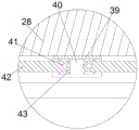
图5为图1中D处放大示意图;Fig. 5 is the enlarged schematic diagram of place D in Fig. 1;
图6为图1中E处放大示意图;Fig. 6 is the enlarged schematic diagram of place E in Fig. 1;
图7为图3中F处放大示意图;FIG. 7 is an enlarged schematic view at F in FIG. 3;
图8为图1中收集块的部分结构示意图;Fig. 8 is a partial structural schematic diagram of the collection block in Fig. 1;
图9为图1中锐器盒的部分结构示意图。Fig. 9 is a partial structural schematic diagram of the sharps box in Fig. 1 .
图中:10、箱体;11、桶盖腔;12、桶盖;13、转动块;14、丢弃腔;15、第一分拣腔;16、齿条;17、滑块;18、第二分拣腔;20、气缸;21、气缸杆;22、驱动电机轴;23、驱动电机;24、装配电机;25、压力腔;26、压力块;27、压力轴;28、收集块;29、收集腔;30、存放腔;31、限制环;32、安装压力板;33、电磁腔;34、电磁铁;35、弹簧;36、弹射腔;37、弹射板;38、弹簧腔;39、固定块;40、反转腔;41、反转轴;42、阻挡板;43、反转电机;44、动力电机;45、动力齿轮;46、动力腔;47、动力轴;48、缓冲板;49、中转腔;50、分隔板;51、锐器盒。In the figure: 10, box body; 11, barrel lid cavity; 12, barrel lid; 13, rotating block; 14, discarding cavity; 15, first sorting cavity; 16, rack; 17, slider; 18, the second Two sorting chambers; 20, cylinders; 21, cylinder rods; 22, drive motor shafts; 23, drive motors; 24, assembly motors; 25, pressure chambers; 26, pressure blocks; 27, pressure shafts; 28, collection blocks; 29. Collection cavity; 30. Storage cavity; 31. Restriction ring; 32. Installation pressure plate; 33. Electromagnetic cavity; 34. Electromagnet; 35. Spring; 36. Ejection cavity; 37. Ejection plate; 38. Spring cavity; 39, fixed block; 40, reverse chamber; 41, reverse shaft; 42, blocking plate; 43, reverse motor; 44, power motor; 45, power gear; 46, power cavity; 47, power shaft; 48, Buffer plate; 49, transfer cavity; 50, partition plate; 51, sharps box.
需要说明的是,附图用于说明本发明,而非限制本发明。注意,表示结构的附图可能并非按比例绘制。并且,附图中,相同或者类似的元件标有相同或者类似的标号。It should be noted that the accompanying drawings are used to illustrate the present invention, but not to limit the present invention. Note that drawings showing structures may not be drawn to scale. And, in the drawings, the same or similar elements are marked with the same or similar symbols.
具体实施方式Detailed ways
为了使本发明的内容更加清楚和易懂,下面结合具体实施例和附图对本发明的内容进行详细描述。In order to make the content of the present invention clearer and easier to understand, the content of the present invention will be described in detail below in conjunction with specific embodiments and accompanying drawings.
本实施例的一种护理通用锐器箱的结构如图1至图9所示,包括箱体10,箱体10的一侧端面内设置有与外界连通的桶盖腔11,桶盖腔11的上侧设置有开口朝上的丢弃腔14,丢弃腔14下侧远离桶盖腔11的方向设置有中转腔49,丢弃腔14与中转腔49之间连通设置有靠近桶盖腔11一侧的第一分拣腔15,丢弃腔14与中转腔49之间连通设置有位于第一分拣腔15远离桶盖腔11一侧的第二分拣腔18,第一分拣腔15与第二分拣腔18的上侧开口之间设置有能够控制第一分拣腔15上侧开口开合的切换组件,中转腔49的下侧连通设置有开口朝前且开口朝向远离桶盖腔11一侧的存放腔30,切换组件包括固定安装在丢弃腔14下端壁且位于第一分拣腔15和第二分拣腔18之间的齿条16,齿条16上侧滑动设置有滑块17,滑块17能够将第一分拣腔15的上侧开口封闭,从而使进入丢弃腔14内的针管进入第二分拣腔18内,滑块17内设置有开口朝下的动力腔46,动力腔46的一侧端壁固定有动力电机44,动力电机44内动力连接有与动力腔46另一侧端壁转动连接的动力轴47,动力轴47上固定有与齿条16上侧啮合的动力齿轮45。The structure of a kind of nursing general-purpose sharps box of the present embodiment is shown in Figure 1 to Figure 9, comprises
桶盖腔11内容纳有若干桶盖12,桶盖腔11下侧设有与存放腔30连通的弹射腔36,弹射腔36的下侧连通设置有弹簧腔38,弹簧腔38的下侧连通设置有电磁腔33,电磁腔33远离存放腔30的一侧端壁内固定安装有电磁铁34,电磁腔33内滑动设置有上侧延伸至弹射腔36内且能够被磁力排斥的弹射板37,弹射板37远离存放腔30的一侧端面与弹簧腔38远离存放腔30的一侧端壁之间固定连接有弹簧35,桶盖腔11内能够放置桶盖12,桶盖12与桶盖腔11之间能够滑动且桶盖腔11内最多放置五个桶盖12。The
中转腔49内转动且滑动设置有圆柱状的收集块28,收集块28内设置有以收集块28轴线为圆心等角度圆周阵列的十二个收集腔29,收集腔29为两组,其中靠近收集块28轴线的一侧为一组即内侧组,远离收集块28轴线的一侧为一组即外侧组,第一分拣腔15的下侧开口与远离收集块28轴线一侧的29对齐,第二分拣腔18的下侧开口与靠近收集块28轴线一侧的29对齐。收集块28的上方设置有控制收集块28转动和升降的驱动组件,驱动组件包括固定在中转腔49的上端壁的气缸20,气缸20的下侧动力连接有可以收缩的气缸杆21,气缸杆21的下侧固定有圆柱状的转动块13,收集块28上端面且位于收集块28的中心轴线处与转动块13的下侧转动配合,转动块13内固定安装有驱动电机23,驱动电机23的下侧动力连接有与收集块28上端面固定连接的驱动电机轴22。收集块28的下侧安装有阻挡组件,阻挡组件包括固定在收集块28下端面的固定块39,固定块39呈前后方向水平安装,固定块39内设置有开口朝下且左右贯通的反转腔40,反转腔40的一侧端壁内固定有关于固定块39左右两端面最短连线的中心分隔线左右对称的反转电机43,反转电机43内动力连接有与反转腔40另一侧端壁转动连接的反转轴41,反转轴41上固定有阻挡板42,阻挡板42呈水平状态时能够将收集腔29的下侧开口封闭,阻挡板42呈竖直状态时收集腔29的下侧开口开启。中转腔49的两侧对称设置有下压组件,下压组件包括设置在中转腔49两侧且关于中转腔49对称的压力腔25,压力腔25开口朝下,压力腔25的上端壁固定有装配电机24,装配电机24的下侧动力连接有压力轴27,压力腔25内滑动设置有与压力轴27螺纹连接的压力块26,压力块26的下端面固定有呈圆环状且位于存放腔30内的安装压力板32。Rotate in the
存放腔30的下端壁固定安装有圆环状的限制环31,存放腔30的上端壁固定设置有位于存放腔30开口一侧的缓冲板48,限制环31的内侧可安装圆柱状的锐器盒51,锐器盒51内固定有以锐器盒51中心轴线为轴心等角度设置的十二个分隔板50,锐器盒51的上侧开口能够与桶盖12进行配合连接。具体使用时,先将桶盖腔11内装满桶盖12,且最下侧的桶盖12位于弹射腔36内,电磁铁34未通电,收集块28位于中转腔49内,安装压力板32上端面与存放腔30上端壁贴合,存放腔30内放置有新的锐器盒51,动力轴47位于第一分拣腔15和第二分拣腔18之间,阻挡板42与水平面平行,医院使用过的一次性针管从丢弃腔14放入,接着在重力作用下沿丢弃腔14的斜面向靠近第一分拣腔15的一侧滑动,从而掉入第一分拣腔15内,接着经由中转腔49插入收集腔29内并被阻挡板42阻拦,接着驱动电机23启动,从而带动驱动电机轴22转动,从而带动收集块28转动,当收集块28旋转六十度时驱动电机23停止,此时第一分拣腔15下侧开口与尚未填充的收集腔29对齐,接着使用过的一次性针管即可再次存入尚未填充的收集腔29内,由此往复,当远离收集块28中心轴线一侧的收集腔29全部填满后,动力电机44启动,从而通过动力轴47带动动力齿轮45转动,从而在齿条16的作用下使滑块17向靠近第一分拣腔15的一侧移动,当滑块17将第一分拣腔15的上侧开口完全封闭后,动力电机44关闭,接着使用过的一次性针管在重力作用下向第二分拣腔18一侧滑动,当一次性针管靠近第二分拣腔18的一侧与滑块17脱离接触时,此时由于针管的重心位置仍位于滑块17的上侧部分,因此此时针管不会产生向下的翻转,当针管持续向靠近第二分拣腔18的一侧移动,使针管重心位置与滑块17脱离接触,此时针管部分已位于第二分拣腔18的上侧开口且此时针管会进行顺时针翻转,进而使针管开始进入第二分拣腔18内,最终进入第二分拣腔18内并通过中转腔49进入靠近收集块28中心轴线一侧的收集腔29内,接着经由上述过程使靠近收集块28内侧的收集腔29全部填满。The lower end wall of the
待所有收集腔29全部填满后,气缸20启动,从而使气缸杆21向下伸长,从而使收集块28向下移动至存放腔30内,进而使收集块28逐渐进入锐器盒51内部空间内,此时收集腔29的下侧与相邻两个分隔板50所分隔成的空间对齐,当收集块28的下端面与锐器盒51上端面平齐时,气缸20关闭,接着反转电机43启动,从而使阻挡板42向靠近固定块39左右两侧端面最短连线的中心轴线的一侧转动,当阻挡板42转动九十度时,反转电机43关闭,再次过程中,收集腔29内的废弃针管在重力作用下向下掉落进入两个相邻分隔板50所分隔成的空间内,最终保证废弃针管在进入两个相邻分隔板50所分隔成的空间内后仍处于静止状态,接着两个反转电机43反转,使阻挡板42恢复水平初始位置,接着气缸20反向启动通过气缸杆21使收集块28向上移动复位至中转腔49内,接着即可通过上述过程将收集腔29重新填满,当收集块28再次向下移动时,由于此时与收集腔29相对齐的两个相邻分隔板50所分隔成的空间内已存储有废弃的针管,因此此时驱动电机23启动,从而通过上述过程带动收集块28转动三十度,接着驱动电机23关闭,接着通过上述过程使收集腔29内存储的废弃针管进入尚未装填的两个相邻分隔板50所分隔成的空间内,由此往复,在收集针管的同时,医护人员也能够将使用完毕后的废弃输液管与针头由存放腔30的前侧开口向锐器盒51内部丢弃,此时这些废弃输液管与废弃针头堆叠在锐器盒51内部的中心处,进而使锐器盒51的空间利用最大化。After all the
当锐器盒51内存储废弃医疗垃圾达到国家规定的标准时,电磁铁34通电,电磁铁34产生磁力并在磁力作用下将弹射板37排斥,从而使弹射板37在磁力的作用下快速向靠近存放腔30的一侧移动,同时弹簧35被拉伸且此时弹簧35的拉力远小于电磁铁34与弹射板37之间的斥力,从而使位于弹射腔36内的桶盖12向存放腔30的方向弹出,最终于缓冲板48发生接触后停止弹射运动并在重力作用下向下掉落至锐器盒51的上端面,接着电磁铁34断电,从而使弹射板37在35的拉力作用下复位滑动并回到起始位置,接着装配电机24启动,从而带动压力轴27转动,从而使缓冲板48逐渐向下移动,进而使安装压力板32逐渐向下移动,进而使安装压力板32向下挤压桶盖12与锐器盒51的接触点,进而将桶盖12与锐器盒51压合安装为一体,接着装配电机24反向启动,从而使安装压力板32向上侧复位,接着装配电机24关闭,最后医护人员将安装完毕的锐器盒51从存放腔30内取出并向存放腔30内放置新的锐器盒51即可,当桶盖腔11内的桶盖12即将用完时,及时通过桶盖腔11的开口侧补充桶盖12即可。When the discarded medical waste stored in the
本实施例一方面能够将废弃针管单独收纳填充,进而避免了针管倾斜与锐器盒内壁相抵的情况,并且也避免了输液管与刀片等废弃物直接堆积在针管表面,使其能够正常在锐器盒内堆叠,从而提高了锐器盒的空间利用率,进而减少了锐器盒的浪费;另一方面能够自动对锐器盒进行安装组合,无需人工提前将锐器盒安装组合,从而减少了医护人员的劳动强度,能够使医护人员专心进行病人救治,提高了医护人员的工作效率。On the one hand, this embodiment can store and fill the waste needle tubes separately, thereby avoiding the situation that the needle tubes are tilted against the inner wall of the sharps box, and also avoiding the direct accumulation of waste such as infusion tubes and blades on the surface of the needle tubes, so that it can be used normally in the sharps box. The sharps box can be stacked in the box, thereby improving the space utilization rate of the sharps box, thereby reducing the waste of the sharps box; It reduces the labor intensity of medical staff, enables medical staff to concentrate on treating patients, and improves the work efficiency of medical staff.
对于任何熟悉本领域的技术人员而言,在不脱离本发明技术方案范围情况下,都可利用上述揭示的技术内容对本发明技术方案作出许多可能的变动和修饰,或修改为等同变化的等效实施例。因此,凡是未脱离本发明技术方案的内容,依据本发明的技术实质对以上实施例所做的任何简单修改、等同变化及修饰,均仍属于本发明技术方案保护的范围内。For any person skilled in the art, without departing from the scope of the technical solution of the present invention, the technical content disclosed above can be used to make many possible changes and modifications to the technical solution of the present invention, or be modified to be equivalent to equivalent changes. Example. Therefore, any simple modifications, equivalent changes and modifications made to the above embodiments according to the technical essence of the present invention, which do not deviate from the technical solution of the present invention, still fall within the protection scope of the technical solution of the present invention.
Claims (10)
Priority Applications (1)
| Application Number | Priority Date | Filing Date | Title |
|---|---|---|---|
| CN202110486662.4A CN113116552B (en) | 2021-05-01 | 2021-05-01 | General sharp instrument box for nursing |
Applications Claiming Priority (1)
| Application Number | Priority Date | Filing Date | Title |
|---|---|---|---|
| CN202110486662.4A CN113116552B (en) | 2021-05-01 | 2021-05-01 | General sharp instrument box for nursing |
Publications (2)
| Publication Number | Publication Date |
|---|---|
| CN113116552A CN113116552A (en) | 2021-07-16 |
| CN113116552B true CN113116552B (en) | 2023-03-14 |
Family
ID=76781009
Family Applications (1)
| Application Number | Title | Priority Date | Filing Date |
|---|---|---|---|
| CN202110486662.4A Expired - Fee Related CN113116552B (en) | 2021-05-01 | 2021-05-01 | General sharp instrument box for nursing |
Country Status (1)
| Country | Link |
|---|---|
| CN (1) | CN113116552B (en) |
Citations (13)
| Publication number | Priority date | Publication date | Assignee | Title |
|---|---|---|---|---|
| FR2494231A1 (en) * | 1980-11-19 | 1982-05-21 | Frontier Plastics South Wales | TRASH CAN |
| CA2615500A1 (en) * | 2005-07-20 | 2007-01-25 | Optimus Services, Llc | Hospital operating room re-design |
| EP2604304A1 (en) * | 2011-12-14 | 2013-06-19 | Sanofi-Aventis Deutschland GmbH | Needle storage magazine |
| CN205391191U (en) * | 2016-01-25 | 2016-07-27 | 北京大学深圳医院 | Sharp machine box convenient to collect sharp ware |
| CN106377323A (en) * | 2016-08-26 | 2017-02-08 | 中国人民解放军第三军医大学第三附属医院 | Edge tool collection box |
| CN106865065A (en) * | 2017-04-27 | 2017-06-20 | 王兴莉 | A kind of new sharp disposable container |
| CN106994051A (en) * | 2016-01-25 | 2017-08-01 | 北京大学深圳医院 | It is easy to collect the sharp instrument box of sharp instrument |
| CN107928801A (en) * | 2015-10-05 | 2018-04-20 | 刘燕平 | Disposable blood specimen collecting needle collection box placing box |
| CN108478286A (en) * | 2018-04-10 | 2018-09-04 | 贾慧霞 | A kind of medical waste retracting device |
| KR20190130524A (en) * | 2019-10-29 | 2019-11-22 | (주)신아메드 | Supply and recovery safe container of pen type insulin syringe needle |
| CN110680510A (en) * | 2019-10-14 | 2020-01-14 | 杭州蒂尔佳仪器有限公司 | Sharp tool box for collecting medical waste device |
| CN210647712U (en) * | 2019-10-16 | 2020-06-02 | 王晗 | Improve automatic rubbing crusher of structure |
| CN111956339A (en) * | 2020-09-01 | 2020-11-20 | 朱力真 | Operation medical waste collecting and storing box |
Family Cites Families (6)
| Publication number | Priority date | Publication date | Assignee | Title |
|---|---|---|---|---|
| US8915362B2 (en) * | 2008-10-08 | 2014-12-23 | Ultimed, Inc. | Sharps container |
| CA2871286C (en) * | 2010-03-30 | 2018-09-11 | Catilina Nominees Pty Ltd | Medical waste disposal apparatus |
| CN104740732B (en) * | 2013-12-27 | 2017-11-14 | 南阳医学高等专科学校 | Hand revolves jack catchs type Medical edged tool box |
| CN104436376A (en) * | 2014-12-21 | 2015-03-25 | 天津市金贵勇胜医疗器械开发有限公司 | Edge tool box for containing medical waste syringe needles |
| CN108478287B (en) * | 2018-05-31 | 2023-07-18 | 芜湖市第二人民医院 | Guided sharps box organizer |
| CN109646117B (en) * | 2018-12-17 | 2024-01-26 | 向天新 | Sharp instrument box capable of being conveniently opened |
-
2021
- 2021-05-01 CN CN202110486662.4A patent/CN113116552B/en not_active Expired - Fee Related
Patent Citations (13)
| Publication number | Priority date | Publication date | Assignee | Title |
|---|---|---|---|---|
| FR2494231A1 (en) * | 1980-11-19 | 1982-05-21 | Frontier Plastics South Wales | TRASH CAN |
| CA2615500A1 (en) * | 2005-07-20 | 2007-01-25 | Optimus Services, Llc | Hospital operating room re-design |
| EP2604304A1 (en) * | 2011-12-14 | 2013-06-19 | Sanofi-Aventis Deutschland GmbH | Needle storage magazine |
| CN107928801A (en) * | 2015-10-05 | 2018-04-20 | 刘燕平 | Disposable blood specimen collecting needle collection box placing box |
| CN106994051A (en) * | 2016-01-25 | 2017-08-01 | 北京大学深圳医院 | It is easy to collect the sharp instrument box of sharp instrument |
| CN205391191U (en) * | 2016-01-25 | 2016-07-27 | 北京大学深圳医院 | Sharp machine box convenient to collect sharp ware |
| CN106377323A (en) * | 2016-08-26 | 2017-02-08 | 中国人民解放军第三军医大学第三附属医院 | Edge tool collection box |
| CN106865065A (en) * | 2017-04-27 | 2017-06-20 | 王兴莉 | A kind of new sharp disposable container |
| CN108478286A (en) * | 2018-04-10 | 2018-09-04 | 贾慧霞 | A kind of medical waste retracting device |
| CN110680510A (en) * | 2019-10-14 | 2020-01-14 | 杭州蒂尔佳仪器有限公司 | Sharp tool box for collecting medical waste device |
| CN210647712U (en) * | 2019-10-16 | 2020-06-02 | 王晗 | Improve automatic rubbing crusher of structure |
| KR20190130524A (en) * | 2019-10-29 | 2019-11-22 | (주)신아메드 | Supply and recovery safe container of pen type insulin syringe needle |
| CN111956339A (en) * | 2020-09-01 | 2020-11-20 | 朱力真 | Operation medical waste collecting and storing box |
Non-Patent Citations (1)
| Title |
|---|
| 新型水平式开关医疗垃圾箱的设计与应用;楚佳琪 张茂芳;《天津护理》;20171228;第25卷(第六期);第1-2页 * |
Also Published As
| Publication number | Publication date |
|---|---|
| CN113116552A (en) | 2021-07-16 |
Similar Documents
| Publication | Publication Date | Title |
|---|---|---|
| CN107777071B (en) | A sterile liquid dispensing device for dipping a cotton swab | |
| CN110432992A (en) | Surgical nursing medical kit | |
| CN113116552B (en) | General sharp instrument box for nursing | |
| CN214714516U (en) | Processing and extracting device of ginkgolide | |
| CN214806857U (en) | A device of decocting medicinal herbs for extracting medicinal material active ingredient | |
| CN113662366B (en) | Classification storage device for medicine delivery inspection | |
| CN213603543U (en) | Glossy ganoderma spore powder extraction element | |
| CN116689166B (en) | Plasma quick separation preparation facilities | |
| CN220282393U (en) | A kind of disinfection trash can | |
| CN219579046U (en) | Multifunctional medical instrument box | |
| CN207806161U (en) | Debirs feeding mechanism | |
| CN111167354A (en) | Medicine automatic shaking device similar to human arm | |
| CN116395300A (en) | Waste collection device for operating room care | |
| CN212333593U (en) | A waste bin that can compress waste | |
| CN114028987A (en) | Even device shakes after blood internal medicine marrow is gathered | |
| CN213443966U (en) | Mammary gland living body specimen storage device for mammary gland department | |
| CN116531809B (en) | Separator that new material processing was used | |
| CN110180647B (en) | A bentonite crushing equipment | |
| CN216258481U (en) | Fat storage and filtration integrated autologous fat collection device | |
| CN219890740U (en) | Animal quarantine sampling device | |
| CN220258105U (en) | Test tube strorage device | |
| CN216547834U (en) | Liquid material quantitative feeding device | |
| CN211298978U (en) | Economic management data cabinet | |
| CN119733587B (en) | A device for crushing medicine for critical care | |
| CN218795445U (en) | An adjustable constant temperature horizontal shaker |
Legal Events
| Date | Code | Title | Description |
|---|---|---|---|
| PB01 | Publication | ||
| PB01 | Publication | ||
| SE01 | Entry into force of request for substantive examination | ||
| SE01 | Entry into force of request for substantive examination | ||
| CB03 | Change of inventor or designer information |
Inventor after: Liang Yan Inventor after: Li Jian Inventor after: Wang Han Inventor before: Wang Han |
|
| CB03 | Change of inventor or designer information | ||
| TA01 | Transfer of patent application right |
Effective date of registration: 20230217 Address after: 410205 tongzipo Road, Yuelu District, Changsha City, Hunan Province Applicant after: THE THIRD XIANGYA HOSPITAL OF CENTRAL SOUTH University Address before: Room 2634, block a, ideal Yintai city apartment, baobaoqiao community, Linping, Yuhang District, Hangzhou City, Zhejiang Province, 311100 Applicant before: Wang Han |
|
| TA01 | Transfer of patent application right | ||
| GR01 | Patent grant | ||
| GR01 | Patent grant | ||
| CF01 | Termination of patent right due to non-payment of annual fee |
Granted publication date: 20230314 |
|
| CF01 | Termination of patent right due to non-payment of annual fee |