CN113099172B - Intelligent monitoring camera with inspection function - Google Patents
Intelligent monitoring camera with inspection function Download PDFInfo
- Publication number
- CN113099172B CN113099172B CN202110248003.7A CN202110248003A CN113099172B CN 113099172 B CN113099172 B CN 113099172B CN 202110248003 A CN202110248003 A CN 202110248003A CN 113099172 B CN113099172 B CN 113099172B
- Authority
- CN
- China
- Prior art keywords
- groove
- block
- track
- bevel gear
- fixed
- Prior art date
- Legal status (The legal status is an assumption and is not a legal conclusion. Google has not performed a legal analysis and makes no representation as to the accuracy of the status listed.)
- Active
Links
- 238000012544 monitoring process Methods 0.000 title claims abstract description 24
- 238000007689 inspection Methods 0.000 title description 8
- 238000001125 extrusion Methods 0.000 claims description 11
- 235000017166 Bambusa arundinacea Nutrition 0.000 claims 4
- 235000017491 Bambusa tulda Nutrition 0.000 claims 4
- 241001330002 Bambuseae Species 0.000 claims 4
- 235000015334 Phyllostachys viridis Nutrition 0.000 claims 4
- 239000011425 bamboo Substances 0.000 claims 4
- 230000005540 biological transmission Effects 0.000 description 3
- 230000007547 defect Effects 0.000 description 2
- 238000005516 engineering process Methods 0.000 description 2
- 238000010030 laminating Methods 0.000 description 2
- 238000012986 modification Methods 0.000 description 2
- 230000004048 modification Effects 0.000 description 2
- 208000025274 Lightning injury Diseases 0.000 description 1
- 230000009286 beneficial effect Effects 0.000 description 1
- 238000010586 diagram Methods 0.000 description 1
- 239000012212 insulator Substances 0.000 description 1
- 210000001503 joint Anatomy 0.000 description 1
Images


Classifications
-
- H—ELECTRICITY
- H04—ELECTRIC COMMUNICATION TECHNIQUE
- H04N—PICTORIAL COMMUNICATION, e.g. TELEVISION
- H04N7/00—Television systems
- H04N7/18—Closed-circuit television [CCTV] systems, i.e. systems in which the video signal is not broadcast
- H04N7/183—Closed-circuit television [CCTV] systems, i.e. systems in which the video signal is not broadcast for receiving images from a single remote source
- H04N7/185—Closed-circuit television [CCTV] systems, i.e. systems in which the video signal is not broadcast for receiving images from a single remote source from a mobile camera, e.g. for remote control
-
- F—MECHANICAL ENGINEERING; LIGHTING; HEATING; WEAPONS; BLASTING
- F16—ENGINEERING ELEMENTS AND UNITS; GENERAL MEASURES FOR PRODUCING AND MAINTAINING EFFECTIVE FUNCTIONING OF MACHINES OR INSTALLATIONS; THERMAL INSULATION IN GENERAL
- F16M—FRAMES, CASINGS OR BEDS OF ENGINES, MACHINES OR APPARATUS, NOT SPECIFIC TO ENGINES, MACHINES OR APPARATUS PROVIDED FOR ELSEWHERE; STANDS; SUPPORTS
- F16M11/00—Stands or trestles as supports for apparatus or articles placed thereon ; Stands for scientific apparatus such as gravitational force meters
- F16M11/42—Stands or trestles as supports for apparatus or articles placed thereon ; Stands for scientific apparatus such as gravitational force meters with arrangement for propelling the support stands on wheels
- F16M11/425—Stands or trestles as supports for apparatus or articles placed thereon ; Stands for scientific apparatus such as gravitational force meters with arrangement for propelling the support stands on wheels along guiding means
-
- G—PHYSICS
- G07—CHECKING-DEVICES
- G07C—TIME OR ATTENDANCE REGISTERS; REGISTERING OR INDICATING THE WORKING OF MACHINES; GENERATING RANDOM NUMBERS; VOTING OR LOTTERY APPARATUS; ARRANGEMENTS, SYSTEMS OR APPARATUS FOR CHECKING NOT PROVIDED FOR ELSEWHERE
- G07C1/00—Registering, indicating or recording the time of events or elapsed time, e.g. time-recorders for work people
- G07C1/20—Checking timed patrols, e.g. of watchman
-
- H—ELECTRICITY
- H02—GENERATION; CONVERSION OR DISTRIBUTION OF ELECTRIC POWER
- H02J—CIRCUIT ARRANGEMENTS OR SYSTEMS FOR SUPPLYING OR DISTRIBUTING ELECTRIC POWER; SYSTEMS FOR STORING ELECTRIC ENERGY
- H02J50/00—Circuit arrangements or systems for wireless supply or distribution of electric power
- H02J50/90—Circuit arrangements or systems for wireless supply or distribution of electric power involving detection or optimisation of position, e.g. alignment
-
- H—ELECTRICITY
- H02—GENERATION; CONVERSION OR DISTRIBUTION OF ELECTRIC POWER
- H02J—CIRCUIT ARRANGEMENTS OR SYSTEMS FOR SUPPLYING OR DISTRIBUTING ELECTRIC POWER; SYSTEMS FOR STORING ELECTRIC ENERGY
- H02J7/00—Circuit arrangements for charging or depolarising batteries or for supplying loads from batteries
- H02J7/0047—Circuit arrangements for charging or depolarising batteries or for supplying loads from batteries with monitoring or indicating devices or circuits
- H02J7/0048—Detection of remaining charge capacity or state of charge [SOC]
-
- H—ELECTRICITY
- H04—ELECTRIC COMMUNICATION TECHNIQUE
- H04N—PICTORIAL COMMUNICATION, e.g. TELEVISION
- H04N23/00—Cameras or camera modules comprising electronic image sensors; Control thereof
- H04N23/60—Control of cameras or camera modules
- H04N23/695—Control of camera direction for changing a field of view, e.g. pan, tilt or based on tracking of objects
-
- Y—GENERAL TAGGING OF NEW TECHNOLOGICAL DEVELOPMENTS; GENERAL TAGGING OF CROSS-SECTIONAL TECHNOLOGIES SPANNING OVER SEVERAL SECTIONS OF THE IPC; TECHNICAL SUBJECTS COVERED BY FORMER USPC CROSS-REFERENCE ART COLLECTIONS [XRACs] AND DIGESTS
- Y02—TECHNOLOGIES OR APPLICATIONS FOR MITIGATION OR ADAPTATION AGAINST CLIMATE CHANGE
- Y02T—CLIMATE CHANGE MITIGATION TECHNOLOGIES RELATED TO TRANSPORTATION
- Y02T10/00—Road transport of goods or passengers
- Y02T10/60—Other road transportation technologies with climate change mitigation effect
- Y02T10/70—Energy storage systems for electromobility, e.g. batteries
Landscapes
- Engineering & Computer Science (AREA)
- General Engineering & Computer Science (AREA)
- Multimedia (AREA)
- Signal Processing (AREA)
- Power Engineering (AREA)
- Mechanical Engineering (AREA)
- Physics & Mathematics (AREA)
- General Physics & Mathematics (AREA)
- Computer Networks & Wireless Communication (AREA)
- Studio Devices (AREA)
- Accessories Of Cameras (AREA)
Abstract
The invention discloses an intelligent monitoring camera with a patrol function, which comprises a track and a wireless charger, wherein a bearing is arranged at the top of the track, a pushing cylinder is connected inside the bearing, a threaded rod is connected inside the pushing cylinder, and a mounting plate is fixed at one end of the threaded rod. This intelligent monitoring camera with patrol and examine function is provided with the motor and can work through controlgear to the motor during operation can drive first bevel gear and rotate, can drive the second bevel gear and rotate when first bevel gear rotates, can drive the rotary rod and rotate when the second bevel gear rotates, can drive the pulley and rotate when the rotary rod rotates, can slide with the spout when the pulley rotates, can drive the movable block and remove when the pulley slides, can drive main part and camera and remove when the movable block removes, can patrol and examine equipment when the camera removes, and the convenience camera can possess the function of patrolling and examining.
Description
Technical Field
The invention relates to the technical field of power monitoring equipment, in particular to an intelligent monitoring camera with a patrol function.
Background
The overhead line mainly refers to an overhead open line, is erected above the ground, and is a power transmission line for transmitting electric energy by fixing a power transmission wire on a tower erected on the ground by using an insulator. The power transmission corridor is convenient to erect and maintain, has low cost, is easily affected by weather and environment (such as strong wind, lightning stroke, pollution, ice and snow and the like) to cause faults, occupies more land area, and is easy to cause electromagnetic interference to surrounding environment. The overhead line is mainly installed in an open area or in a tunnel or a pipe gallery, when a cable is installed in the tunnel or the pipe gallery, frequent inspection is required, inspection is usually performed manually or a large number of cameras are installed for monitoring, the monitored range of the cameras is limited, monitoring dead angles are often not monitored, and therefore an intelligent monitoring camera with an inspection function is required for inspection monitoring, and the type of an electric quantity monitor used in the invention is GY-6D.
The intelligent monitoring camera in the current market has a plurality of defects, does not have a patrol function, is inconvenient to adjust the height of a track, is inconvenient to assemble and overhaul, does not have a wireless charging function, and therefore the technology capable of improving the intelligent monitoring camera structure with the patrol function is urgently needed in the market to perfect the equipment.
Disclosure of Invention
The invention aims to provide an intelligent monitoring camera with a patrol function, which solves the problems that the intelligent monitoring camera in the current market provided by the background technology has a plurality of defects, does not have the patrol function, is inconvenient to adjust the height of a track, is inconvenient to assemble the track, is inconvenient to overhaul and does not have a wireless charging function.
In order to achieve the above purpose, the present invention provides the following technical solutions: an intelligent monitoring camera with a patrol function comprises a track and a wireless charger, wherein a bearing is arranged at the top of the track,
the bearing is internally connected with a pushing cylinder, the pushing cylinder is internally connected with a threaded rod, one end of the threaded rod is fixedly provided with a mounting plate, one end of the track is provided with a connecting groove, a first fixed block is embedded in the connecting groove, the top of the first fixed block is fixedly provided with a pushing block, the front side and the rear side of the first fixed block are provided with extrusion grooves, the inside of the extrusion grooves is provided with springs, one side of each spring is fixedly provided with a positioning block, the other end of the track is provided with a first fixed groove, two sides of the first fixed groove close to the positioning block are provided with positioning grooves, and the inside of each positioning groove is connected with a pressing block;
the track bottom is provided with a sliding groove, a moving block is embedded in the sliding groove, a motor is arranged in the moving block, one end of the motor is connected with a first bevel gear, a rotating rod is connected to the moving block, which is close to the motor, one side of the rotating rod, which is close to the first bevel gear, is connected with a second bevel gear, one side of the rotating rod, which is close to the sliding groove, is connected with a pulley, the bottom of the moving block is fixedly provided with a first connecting block, one end of the first connecting block is provided with a second fixing groove, one side of the second fixing groove is provided with a guide groove, and one end of the guide groove is provided with a rotating groove;
the utility model discloses a wireless charger, including rotatory groove, screw thread groove internally connected has the bolt, is close to the bolt rotatory inslot gomphosis has the guide block, be fixed with the second fixed block between the guide block, second fixed block one side is fixed with the second connecting block, the main part is installed to second connecting block one end, the camera is installed to the main part bottom, main part internally mounted has the battery electric quantity watch-dog is installed to battery one side, is close to electric quantity watch-dog main part internally mounted has control equipment, is close to control equipment main part internally mounted has the transmitter, track one side is connected with initial track, wireless charger installs in initial track one end.
Preferably, a rotating structure is formed between the track and the pushing cylinder through a bearing, and the pushing cylinder is in threaded connection with the threaded rod.
Preferably, the connecting groove and the pushing block form sliding connection through the first fixing block, and the vertical section of the first fixing block is the same as the vertical section of the first fixing groove in size.
Preferably, a telescopic structure is formed between the extrusion groove and the positioning block through a spring, and the maximum telescopic size of the positioning block does not exceed the deformation amount of the spring.
Preferably, the vertical section of the positioning block and the vertical section of the positioning groove are the same as the vertical section of the pressing block in size, and the positioning groove is in sliding connection with the pressing block.
Preferably, the first bevel gear has the same size as the second bevel gear, and the first bevel gear is in meshing connection with the second bevel gear.
Preferably, the pulleys are provided with four groups, a rotating structure is formed between the pulleys and the moving block through a rotating rod, the diameter of the pulleys is the same as the height of the sliding groove, and the pulleys are in sliding connection with the sliding groove.
Preferably, the guide groove, the rotary groove and the guide block are provided with two groups, the guide groove and the guide block are in sliding connection, and a rotary structure is arranged between the rotary groove and the guide block.
Preferably, two groups of thread grooves and bolts are arranged, and the thread grooves are in threaded connection with the bolts.
Preferably, the camera is connected with the control device through a wire, the control device is connected with the emitter through a wire, the control device is connected with the electric quantity monitor through a wire, the electric quantity monitor is connected with the battery through a wire, and the control device is connected with the motor through a wire.
Compared with the prior art, the invention has the beneficial effects that: this intelligent monitoring camera with patrol and examine function:
1. the motor can work through the control equipment, so that the motor can drive the first bevel gear to rotate when working, the first bevel gear can drive the second bevel gear to rotate when rotating, the second bevel gear can drive the rotary rod to rotate when rotating, the rotary rod can drive the pulley to rotate when rotating, the pulley can slide with the chute when rotating, the pulley can drive the moving block to move while sliding, the moving block can drive the main body to move with the camera when moving, the camera can patrol the equipment when moving, and the camera can conveniently have a patrol function;
2. the threaded rod can slide in a threaded manner through the rotary pushing cylinder, so that the pushing cylinder can rotate with the track through the bearing when in threaded sliding, the pushing cylinder can push the track to move when rotating with the bearing and the track, the height of the camera can be adjusted when the track moves, and the height of the track can be adjusted according to the use requirement conveniently;
3. the screw groove is formed in the camera body, the screw groove can slide in a screw manner through rotating the bolt, so that the bolt can be separated from the guide block in the screw manner, the second connecting block can be rotated to drive the second fixed block to rotate with the guide block after the bolt is separated from the guide block, the guide block can be rotated to rotate with the rotating groove, the second connecting block can be pulled to drive the second fixed block to move downwards with the guide block after the guide block rotates to one end of the rotating groove, the guide block can slide with the guide groove after moving downwards, the guide block can overhaul the camera after sliding out of the guide groove, and the camera can be overhauled quickly conveniently;
4. the two groups of rails are butted, the connecting grooves can be driven to be butted with the first fixing grooves during rail butt joint, the pushing blocks can be pulled to drive the first fixing blocks to move after the connecting grooves are butted with the first fixing grooves, the first fixing blocks can be inserted into the first fixing grooves during moving, the positioning blocks can be driven to move to the positions of the positioning grooves when the first fixing blocks are inserted into the first fixing grooves, after the positioning blocks move to the positions of the positioning grooves, the positioning blocks can reset through the self elasticity of the springs, the positioning blocks can be inserted into the positioning grooves to be fixed after reset, and rapid assembly between the rails is facilitated;
5. the battery can supply power to intelligent monitoring camera, can the electric quantity watch-dog monitor send the instruction to controlgear to it when battery electric quantity is lower, can start the motor after the controlgear receives the instruction and make pulley and spout slip, pulley slip makes can drive the main part in the initial orbit, can remove wireless charger one side after the main part removes initial orbit, can make battery and wireless charger produce the laminating after the main part removes wireless charger one side, and wireless charger can charge the battery when battery and wireless charger laminating, makes things convenient for intelligent monitoring camera can possess wireless charging function.
Drawings
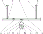
FIG. 1 is a schematic view of a front view partially in section;
FIG. 2 is a schematic top view of the present invention;
FIG. 3 is a schematic top view of a first connecting block according to the present invention;
FIG. 4 is an enlarged schematic view of the structure of the portion A of the present invention;
FIG. 5 is an enlarged view of the structure of the portion B of the present invention;
FIG. 6 is an enlarged view of the structure of the C part of the present invention;
FIG. 7 is a schematic diagram of a workflow structure according to the present invention.
In the figure: 1. a track; 2. a bearing; 3. a pushing cylinder; 4. a threaded rod; 5. a mounting plate; 6. a connecting groove; 7. a first fixed block; 8. a pushing block; 9. an extrusion groove; 10. a spring; 11. a positioning block; 12. a first fixing groove; 13. a positioning groove; 14. pressing the blocks; 15. a chute; 16. a moving block; 17. a motor; 18. a first bevel gear; 19. a rotating rod; 20. a second bevel gear; 21. a pulley; 22. a first connection block; 23. a second fixing groove; 24. a guide groove; 25. a rotary groove; 26. a thread groove; 27. a bolt; 28. a guide block; 29. a second fixed block; 30. a second connection block; 31. a main body; 32. a camera; 33. a battery; 34. an electric quantity monitor; 35. a control device; 36. a transmitter; 37. a starting track; 38. a wireless charger.
Detailed Description
The following description of the embodiments of the present invention will be made clearly and completely with reference to the accompanying drawings, in which it is apparent that the embodiments described are only some embodiments of the present invention, but not all embodiments. All other embodiments, which can be made by those skilled in the art based on the embodiments of the invention without making any inventive effort, are intended to be within the scope of the invention.
Referring to fig. 1-7, the present invention provides a technical solution: an intelligent monitoring camera with a patrol function comprises a track 1, a bearing 2, a pushing barrel 3, a threaded rod 4, a mounting plate 5, a connecting groove 6, a first fixed block 7, a pushing block 8, a squeezing groove 9, a spring 10, a positioning block 11, a first fixed groove 12, a positioning groove 13, a pressing block 14, a sliding groove 15, a moving block 16, a motor 17, a first bevel gear 18, a rotating rod 19, a second bevel gear 20, a pulley 21, a first connecting block 22, a second fixed groove 23, a guiding groove 24, a rotating groove 25, a threaded groove 26, a bolt 27, a guiding block 28, a second fixed block 29, a second connecting block 30, a main body 31, a camera 32, a battery 33, an electric quantity monitor 34, a control device 35, a transmitter 36, a starting track 37 and a wireless charger 38, wherein the top of the track 1 is provided with a bearing 2, a rotating structure is formed between the track 1 and the pushing barrel 3 through the bearing 2, the pushing barrel 3 and the threaded rod 4 are in threaded connection, the rotating pushing barrel 3 can slide with the threaded rod 4, when the pushing barrel 3 slides with threads, the track 2 and the track 1 can be pushed by pushing the bearing 2 and the rotating barrel 3, the track 1 can be simultaneously moved with the track 1, the track 32 can be moved, and the track 1 can be moved with the height of the track 1,
the bearing 2 is internally connected with the pushing cylinder 3, the pushing cylinder 3 is internally connected with the threaded rod 4, one end of the threaded rod 4 is fixedly provided with the mounting plate 5, one end of the track 1 is provided with the connecting groove 6, the connecting groove 6 and the pushing block 8 form sliding connection through the first fixing block 7, the vertical section of the first fixing block 7 is the same as the vertical section of the first fixing groove 12 in size, the connecting groove 6 can be driven to be butted with the first fixing groove 12 when the track 1 is butted, the pushing block 8 can be pulled to drive the first fixing block 7 to move after the connecting groove 6 is butted with the first fixing groove 12, the first fixing block 7 can be inserted into the first fixing groove 12 when the first fixing block 7 moves, the first fixing block 7 is embedded in the connecting groove 6, the pushing block 8 is fixed at the top of the first fixing block 7, the extrusion grooves 9 are arranged on the front side and the rear side of the first fixing block 7, the extrusion groove 9 and the positioning block 11 form a telescopic structure through a spring 10, the maximum telescopic size of the positioning block 11 is not larger than the deformation of the spring 10, the positioning block 11 can be driven to move to the position of the positioning groove 13 when the first fixed block 7 is inserted into the first fixed groove 12, the positioning block 11 can be reset through the self elastic force of the spring 10 after moving to the position of the positioning groove 13, the positioning block 11 can be inserted into the positioning groove 13 for fixing after being reset, the spring 10 is arranged in the extrusion groove 9, the positioning block 11 is fixed on one side of the spring 10, the vertical section of the positioning block 11 and the vertical section of the positioning groove 13 are the same as the vertical section size of the pressing block 14, the positioning groove 13 and the pressing block 14 are in sliding connection, the pressing block 14 can slide with the positioning groove 13, the positioning block 11 can be extruded out of the positioning groove 13 when the pressing block 14 slides, the other end of the track 1 is provided with a first fixed groove 12, two sides of the first fixed groove 12, which are close to the positioning block 11, are provided with positioning grooves 13, and the inside of the positioning grooves 13 is connected with a pressing block 14;
the bottom of the track 1 is provided with a chute 15, a moving block 16 is embedded in the chute 15, a motor 17 is arranged in the moving block 16, one end of the motor 17 is connected with a first bevel gear 18, the size of the first bevel gear 18 is the same as that of a second bevel gear 20, the first bevel gear 18 and the second bevel gear 20 are in meshing connection, the motor 17 can drive the first bevel gear 18 to rotate when working, the second bevel gear 20 can be driven to rotate when the first bevel gear 18 rotates, the second bevel gear 20 can drive a rotating rod 19 to rotate when rotating, a rotating rod 19 is connected in the moving block 16 near the motor 17, one side of the rotating rod 19 near the first bevel gear 18 is connected with the second bevel gear 20, one side of the rotating rod 19 near the chute 15 is connected with a pulley 21, the pulley 21 is provided with four groups, the pulley 21 and the moving block 16 form a rotating structure through the rotating rod 19, the diameter of the pulley 21 is the same as the height of the chute 15, the pulley 21 and the chute 15 are in sliding connection, the rotating rod 19 can drive the pulley 21 to rotate when rotating, the pulley 21 can slide with the chute 15 when rotating, the moving block 16 can be driven to move when the pulley 21 slides, the main body 31 and the camera 32 can be driven to move when the moving block 16 moves, the bottom of the moving block 16 is fixedly provided with a first connecting block 22, one end of the first connecting block 22 is provided with a second fixing groove 23, one side of the second fixing groove 23 is provided with a guide groove 24, the rotating groove 25 and the guide block 28 are provided with two groups, the guide groove 24 and the guide block 28 are in sliding connection, the rotating groove 25 and the guide block 28 are in a rotating structure, the second connecting block 30 can be rotated to drive the second fixed block 29 and the guide block 28 to rotate, the guide block 28 can rotate with the rotary groove 25 when rotated, when the guide block 28 rotates to one end of the rotary groove 25, the second connecting block 30 can be pulled to drive the second fixed block 29 and the guide block 28 to move downwards, the guide block 28 moves downwards to slide with the guide groove 24, the guide block 28 can overhaul the camera 32 after sliding out of the guide groove 24, and one end of the guide groove 24 is provided with the rotary groove 25;
the screw groove 26 is arranged on one side of the rotary groove 25, two groups of screw grooves 26 and bolts 27 are arranged, the screw grooves 26 and the bolts 27 are in threaded connection, the rotary bolts 27 can slide with the screw grooves 26 in a threaded manner, the bolts 27 can be separated from the guide blocks 28 when sliding in a threaded manner, the bolts 27 are connected inside the screw grooves 26, the guide blocks 28 are embedded inside the rotary groove 25 close to the bolts 27, a second fixing block 29 is fixed between the guide blocks 28, a second connecting block 30 is fixed on one side of the second fixing block 29, a main body 31 is arranged at one end of the second connecting block 30, a camera 32 is arranged at the bottom of the main body 31, the camera 32 is connected with a control device 35 through wires, the control device 35 is connected with a transmitter 36 through wires, the control device 35 is connected with a power monitor 34 through wires, the electric quantity monitor 34 is connected with the battery 33 through a wire, the control device 35 is connected with the motor 17 through a wire, the battery 33 can supply power to the intelligent monitoring camera, when the electric quantity of the battery 33 is low, the electric quantity monitor 34 can monitor the electric quantity and send instructions to the control device 35, the control device 35 can start the motor 17 to slide the pulley 21 and the chute 15 after receiving the instructions, the pulley 21 slides to drive the main body 31 into the initial track 37, when the main body 31 moves to the initial track 37, the main body 31 moves to the side of the wireless charger 38, the battery 33 is attached to the wireless charger 38 after the main body 31 moves to the side of the wireless charger 38, the wireless charger 38 charges the battery 33 when the battery 33 is attached to the wireless charger 38, the electric quantity monitor 34 is arranged on the side of the battery 33 inside the main body 31, the main body 31 close to the electric quantity monitor 34 is internally provided with a control device 35, the main body 31 close to the control device 35 is internally provided with a transmitter 36, one side of the track 1 is connected with a starting track 37, and the wireless charger 38 is arranged at one end of the starting track 37.
Working principle: when the intelligent monitoring camera with the inspection function is used, firstly, the intelligent monitoring camera with the inspection function needs to be simply understood, when the intelligent monitoring camera is used, the rails 1 need to be assembled, two groups of rails 1 are butted, the connecting groove 6 can be driven to be butted with the first fixing groove 12 when the rails 1 are butted, the pushing block 8 can be pulled to drive the first fixing block 7 to move after the connecting groove 6 is butted with the first fixing groove 12, the first fixing block 7 can be inserted into the first fixing groove 12 when being moved, the positioning block 11 can be driven to move to the position of the positioning groove 13 when the first fixing block 7 is inserted into the first fixing groove 12, the positioning block 11 can be reset through the self elasticity of the spring 10 after the positioning block 11 is moved to the position of the positioning groove 13, the positioning block 11 can be inserted into the positioning groove 13 for fixing after being reset, after the rails 1 are assembled, the mounting plate 5 is fixed to a designated position through screws, the rotating pushing cylinder 3 can slide with the threaded rod 4 in a threaded manner after the mounting plate 5 is mounted, the pushing cylinder 3 can rotate with the track 1 through the bearing 2 when the pushing cylinder 3 slides with the bearing 2 and the track 1, the pushing cylinder 3 can push the track 1 to move when the pushing cylinder 3 rotates with the bearing 2 and the track 1, the track 1 can be used after the height adjustment is finished, the control device 35 works to enable the motor 17 to work when in use, the motor 17 can drive the first bevel gear 18 to rotate when in use, the first bevel gear 18 can drive the second bevel gear 20 to rotate when in rotation, the second bevel gear 20 can drive the rotating rod 19 to rotate when in rotation, the rotating rod 19 can drive the pulley 21 to rotate when in rotation, the pulley 21 can slide with the sliding groove 15, the pulley 21 can drive the moving block 16 to move when in sliding, the moving block 16 can drive the main body 31 and the camera 32 to move when moving, the camera 32 can patrol the equipment when moving, the camera 32 can supply the required electric quantity through the battery 33 when working, the electric quantity monitor 34 can monitor the electric quantity of the battery 33 to send an instruction to the control equipment 35 when the electric quantity of the battery 33 is lower, the control equipment 35 can start the motor 17 to enable the pulley 21 to slide with the chute 15 after receiving the instruction, the pulley 21 can drive the main body 31 to move into the initial track 37, the main body 31 can move to one side of the wireless charger 38 after moving to the initial track 37, the battery 33 can be attached to the wireless charger 38 after moving to one side of the wireless charger 38, the wireless charger 38 can charge the battery 33 when the battery 33 is attached to the wireless charger 38, the camera 32 needs to be overhauled regularly for a long time, the overhauling enables the rotating bolt 27 to slide with the thread groove 26 in a threaded manner, the bolt 27 can be separated from the guide block 28 in a threaded manner, the second connecting block 30 can drive the second fixing block 29 to rotate with the guide block 28 after the bolt 27 is separated from the guide block 28, the guide block 28 can rotate with the rotating groove 25 in a rotating manner, the second connecting block 30 can be pulled to drive the second fixing block 29 to move downwards with the guide block 28 after the guide block 28 rotates to one end of the rotating groove 25, the guide block 28 can slide with the guide groove 24 in a downwards moving manner, and the camera 32 can be overhauled after the guide block 28 slides out of the guide groove 24.
Although the present invention has been described with reference to the foregoing embodiments, it will be apparent to those skilled in the art that modifications may be made to the embodiments described, or equivalents may be substituted for elements thereof, and any modifications, equivalents, improvements and changes may be made without departing from the spirit and principles of the present invention.
Claims (1)
1. An intelligent monitoring camera with patrol and examine function, includes track (1) and wireless charger (38), its characterized in that: the top of the track (1) is provided with a bearing (2), wherein,
the bearing (2) internally connected with promotes section of thick bamboo (3), constitute revolution mechanic through bearing (2) between track (1) and the promotion section of thick bamboo (3) to be threaded connection between promotion section of thick bamboo (3) and threaded rod (4), promotion section of thick bamboo (3) internally connected with threaded rod (4), threaded rod (4) one end is fixed with mounting panel (5), spread groove (6) have been seted up to track (1) one end, constitute sliding connection through first fixed block (7) between spread groove (6) and the promotion piece (8), and the vertical cross-section of first fixed block (7) is the same with the vertical cross-section size of first fixed slot (12), inside gomphosis of spread groove (6) has first fixed block (7), extrusion groove (9) have been seted up at first fixed block (7) top, through spring (10) constitution expansion structure between extrusion groove (9) and the piece (11), and the biggest size of locating piece (11) does not exceed spring (10) shape, extrusion piece (10) have one side of spring (11), the inside is fixed cross-section (10), extrusion piece (7) top is fixed with inside The vertical section of the positioning groove (13) is the same as the vertical section of the pressing block (14), the positioning groove (13) is in sliding connection with the pressing block (14), a first fixing groove (12) is formed in the other end of the track (1), positioning grooves (13) are formed in two sides of the first fixing groove (12) close to the positioning block (11), and the pressing block (14) is connected inside the positioning groove (13);
the utility model discloses a fixed guide groove, including track (1), wherein spout (15) have been seted up to inside gomphosis of spout (15), movable block (16) internally mounted has motor (17), motor (17) one end is connected with first bevel gear (18), the size of first bevel gear (18) is the same with the size of second bevel gear (20), and be the meshing between first bevel gear (18) and second bevel gear (20), be close to motor (17) movable block (16) internally connected with rotary rod (19), be close to first bevel gear (18) rotary rod (19) one side is connected with second bevel gear (20), be close to spout (15) rotary rod (19) one side is connected with pulley (21), pulley (21) are provided with four groups, and constitute rotary structure through rotary rod (19) between pulley (21) and movable block (16), and the diameter of pulley (21) is the same with the high size of spout (15), be sliding connection between pulley (21) and spout (15), movable block (16) bottom (16) are connected with second connecting groove (23), first connecting groove (23) are seted up to one side, the guide grooves (24), the rotating grooves (25) and the guide blocks (28) are arranged in two groups, the guide grooves (24) are in sliding connection with the guide blocks (28), the rotating grooves (25) and the guide blocks (28) are in a rotating structure, and one end of each guide groove (24) is provided with the corresponding rotating groove (25);
screw thread groove (26) have been seted up to rotary groove (25) one side, screw thread groove (26) are provided with two sets of with bolt (27), and be threaded connection between screw thread groove (26) and bolt (27), screw thread groove (26) internal connection has bolt (27), is close to between rotary groove (25) internal mosaic of bolt (27) has guide block (28), be fixed with second fixed block (29) between guide block (28), second fixed block (29) one side is fixed with second connecting block (30), main part (31) are installed to second connecting block (30) one end, camera (32) are installed to main part (31) bottom, pass through wire connection between camera (32) and control device (35), and pass through wire connection between control device (35) and the transmitter (36), and pass through wire connection between control device (35) and the electric quantity watch-dog (34) through wire connection between electric quantity watch-dog (34), pass through wire connection between control device (35) and motor (17) main part (31), electric quantity controller (33) are installed to main part (33) bottom is installed to electric quantity controller (35), the main body (31) close to the control equipment (35) is internally provided with a transmitter (36), one side of the track (1) is connected with a starting track (37), and the wireless charger (38) is arranged at one end of the starting track (37).
Priority Applications (1)
| Application Number | Priority Date | Filing Date | Title |
|---|---|---|---|
| CN202110248003.7A CN113099172B (en) | 2021-03-06 | 2021-03-06 | Intelligent monitoring camera with inspection function |
Applications Claiming Priority (1)
| Application Number | Priority Date | Filing Date | Title |
|---|---|---|---|
| CN202110248003.7A CN113099172B (en) | 2021-03-06 | 2021-03-06 | Intelligent monitoring camera with inspection function |
Publications (2)
| Publication Number | Publication Date |
|---|---|
| CN113099172A CN113099172A (en) | 2021-07-09 |
| CN113099172B true CN113099172B (en) | 2023-06-02 |
Family
ID=76666980
Family Applications (1)
| Application Number | Title | Priority Date | Filing Date |
|---|---|---|---|
| CN202110248003.7A Active CN113099172B (en) | 2021-03-06 | 2021-03-06 | Intelligent monitoring camera with inspection function |
Country Status (1)
| Country | Link |
|---|---|
| CN (1) | CN113099172B (en) |
Families Citing this family (2)
| Publication number | Priority date | Publication date | Assignee | Title |
|---|---|---|---|---|
| CN114112666B (en) * | 2021-11-23 | 2023-11-21 | 徐州市华为工程机械有限公司 | Joint detection device |
| CN114520865B (en) * | 2022-04-20 | 2022-07-22 | 广东信通通信有限公司 | Ad hoc network video terminal equipment capable of realizing autonomous maintenance alarm function |
Citations (4)
| Publication number | Priority date | Publication date | Assignee | Title |
|---|---|---|---|---|
| CN106679813A (en) * | 2016-11-21 | 2017-05-17 | 深圳供电局有限公司 | Intelligent detection system for tunnel power equipment |
| CN107239072A (en) * | 2016-03-29 | 2017-10-10 | 杨志强 | A kind of outdoor automatic tour inspection system |
| CN209887599U (en) * | 2019-03-11 | 2020-01-03 | 上海华常机电工程技术有限公司 | Track inspection robot |
| CN111152236A (en) * | 2020-01-19 | 2020-05-15 | 辽宁工程技术大学 | Inspection robot for safety detection of mining belt conveyor |
-
2021
- 2021-03-06 CN CN202110248003.7A patent/CN113099172B/en active Active
Patent Citations (4)
| Publication number | Priority date | Publication date | Assignee | Title |
|---|---|---|---|---|
| CN107239072A (en) * | 2016-03-29 | 2017-10-10 | 杨志强 | A kind of outdoor automatic tour inspection system |
| CN106679813A (en) * | 2016-11-21 | 2017-05-17 | 深圳供电局有限公司 | Intelligent detection system for tunnel power equipment |
| CN209887599U (en) * | 2019-03-11 | 2020-01-03 | 上海华常机电工程技术有限公司 | Track inspection robot |
| CN111152236A (en) * | 2020-01-19 | 2020-05-15 | 辽宁工程技术大学 | Inspection robot for safety detection of mining belt conveyor |
Also Published As
| Publication number | Publication date |
|---|---|
| CN113099172A (en) | 2021-07-09 |
Similar Documents
| Publication | Publication Date | Title |
|---|---|---|
| CN113099172B (en) | Intelligent monitoring camera with inspection function | |
| CN108673467B (en) | Transformer substation live-line maintenance operation robot system and method | |
| CN109506098A (en) | A kind of electric wire video on-Line Monitor Device | |
| CN211209236U (en) | Adjustable electric power transmission device | |
| CN111473194B (en) | Building engineering environment supervise device | |
| CN114920076B (en) | Dedicated cable winding equipment is erect in construction of electric power transmission cable | |
| CN115164984A (en) | Intelligent monitoring system for green building | |
| CN206506307U (en) | A kind of charging pile executing agency | |
| CN220190427U (en) | High-stability overhead transmission device for line | |
| CN220851568U (en) | Video monitoring system for electric power construction site | |
| CN220980875U (en) | Monitoring device convenient to adjust | |
| CN220544589U (en) | Intelligent repair shock-proof hammer device | |
| CN220858202U (en) | Automatic inspection device of intelligent monitoring camera | |
| CN220923838U (en) | Charging pile with multiple power supply heads | |
| CN210558569U (en) | Photovoltaic line coiling mechanism | |
| CN214895176U (en) | Low-cost miniature air quality monitoring station | |
| CN217453891U (en) | A tour robot for distribution network automation overhauls | |
| CN221508936U (en) | Inspection robot | |
| CN216118503U (en) | Intelligent sensing mechanism for inclination angle of 5G communication tower based on Internet of things | |
| CN220005089U (en) | Snow-covering cleaning device for insulator of power transmission line | |
| CN221405457U (en) | Inside cleanliness monitoring devices of gear box | |
| CN220234840U (en) | Security protection system is with camera of angle regulation of being convenient for | |
| CN221023333U (en) | Power equipment device | |
| CN220692773U (en) | Connector for bus duct | |
| CN219592530U (en) | Three-span video monitoring device for power transmission line |
Legal Events
| Date | Code | Title | Description |
|---|---|---|---|
| PB01 | Publication | ||
| PB01 | Publication | ||
| SE01 | Entry into force of request for substantive examination | ||
| SE01 | Entry into force of request for substantive examination | ||
| GR01 | Patent grant | ||
| GR01 | Patent grant |