CN113040552B - Convenient chair with protection function - Google Patents
Convenient chair with protection function Download PDFInfo
- Publication number
- CN113040552B CN113040552B CN202110471276.8A CN202110471276A CN113040552B CN 113040552 B CN113040552 B CN 113040552B CN 202110471276 A CN202110471276 A CN 202110471276A CN 113040552 B CN113040552 B CN 113040552B
- Authority
- CN
- China
- Prior art keywords
- vertical
- wire pressing
- cylinder
- lifting cylinder
- parts
- Prior art date
- Legal status (The legal status is an assumption and is not a legal conclusion. Google has not performed a legal analysis and makes no representation as to the accuracy of the status listed.)
- Active
Links
- 230000000007 visual effect Effects 0.000 claims abstract description 23
- 230000005540 biological transmission Effects 0.000 claims abstract description 10
- 239000002184 metal Substances 0.000 claims abstract description 9
- 230000001681 protective effect Effects 0.000 claims description 38
- 235000017166 Bambusa arundinacea Nutrition 0.000 claims description 18
- 235000017491 Bambusa tulda Nutrition 0.000 claims description 18
- 241001330002 Bambuseae Species 0.000 claims description 18
- 235000015334 Phyllostachys viridis Nutrition 0.000 claims description 18
- 239000011425 bamboo Substances 0.000 claims description 18
- 238000003780 insertion Methods 0.000 claims description 2
- 230000037431 insertion Effects 0.000 claims description 2
- 229910000831 Steel Inorganic materials 0.000 description 4
- 239000010959 steel Substances 0.000 description 4
- BGPVFRJUHWVFKM-UHFFFAOYSA-N N1=C2C=CC=CC2=[N+]([O-])C1(CC1)CCC21N=C1C=CC=CC1=[N+]2[O-] Chemical compound N1=C2C=CC=CC2=[N+]([O-])C1(CC1)CCC21N=C1C=CC=CC1=[N+]2[O-] BGPVFRJUHWVFKM-UHFFFAOYSA-N 0.000 description 3
- 238000000034 method Methods 0.000 description 3
- 238000001179 sorption measurement Methods 0.000 description 3
- 230000000149 penetrating effect Effects 0.000 description 2
- 230000004075 alteration Effects 0.000 description 1
- 230000007547 defect Effects 0.000 description 1
- 229920001821 foam rubber Polymers 0.000 description 1
- 238000009434 installation Methods 0.000 description 1
- 238000012986 modification Methods 0.000 description 1
- 230000004048 modification Effects 0.000 description 1
- 238000006467 substitution reaction Methods 0.000 description 1
Images


Classifications
-
- A—HUMAN NECESSITIES
- A47—FURNITURE; DOMESTIC ARTICLES OR APPLIANCES; COFFEE MILLS; SPICE MILLS; SUCTION CLEANERS IN GENERAL
- A47C—CHAIRS; SOFAS; BEDS
- A47C7/00—Parts, details, or accessories of chairs or stools
- A47C7/62—Accessories for chairs
-
- A—HUMAN NECESSITIES
- A47—FURNITURE; DOMESTIC ARTICLES OR APPLIANCES; COFFEE MILLS; SPICE MILLS; SUCTION CLEANERS IN GENERAL
- A47C—CHAIRS; SOFAS; BEDS
- A47C1/00—Chairs adapted for special purposes
-
- A—HUMAN NECESSITIES
- A47—FURNITURE; DOMESTIC ARTICLES OR APPLIANCES; COFFEE MILLS; SPICE MILLS; SUCTION CLEANERS IN GENERAL
- A47C—CHAIRS; SOFAS; BEDS
- A47C7/00—Parts, details, or accessories of chairs or stools
-
- A—HUMAN NECESSITIES
- A47—FURNITURE; DOMESTIC ARTICLES OR APPLIANCES; COFFEE MILLS; SPICE MILLS; SUCTION CLEANERS IN GENERAL
- A47C—CHAIRS; SOFAS; BEDS
- A47C7/00—Parts, details, or accessories of chairs or stools
- A47C7/36—Supports for the head or the back
- A47C7/38—Supports for the head or the back for the head, e.g. detachable
-
- A—HUMAN NECESSITIES
- A47—FURNITURE; DOMESTIC ARTICLES OR APPLIANCES; COFFEE MILLS; SPICE MILLS; SUCTION CLEANERS IN GENERAL
- A47C—CHAIRS; SOFAS; BEDS
- A47C7/00—Parts, details, or accessories of chairs or stools
- A47C7/54—Supports for the arms
Landscapes
- Health & Medical Sciences (AREA)
- Dentistry (AREA)
- General Health & Medical Sciences (AREA)
- Special Chairs (AREA)
Abstract
The invention discloses a convenient chair with a protection function, which comprises a left lifting cylinder, a left visual window, a left wire pressing seat, a left wire pressing bolt, a permanent magnet, a right lifting cylinder, a right visual window, a right wire pressing seat, a right wire pressing bolt, a metal sheet, a sponge ring, an infrared sensor, a battery box, an ultrasonic generator, a button switch, a handle and a transmission part, wherein the front part and the rear part of the left lifting cylinder are respectively fixed with a vertical left visual window, and the front part and the rear part of the left lifting cylinder are respectively fixed with a horizontal left wire pressing seat. According to the invention, the space formed by the left protection barrel, the right protection barrel, the left lifting barrel and the right lifting barrel is increased, so that the device can be worn on the head of a student, and the sponge ring is attached to the top of the head of the student, thereby sufficiently protecting the head and the cervical vertebra of the student, and the sponge pad can be buckled on the shoulder of the student, so that the arm of the student can swing conveniently, the arm can not swing and the falling caused by the arm can not swing can be prevented, and the probability of trampling events can be reduced.
Description
Technical Field
The invention relates to the field of furniture, in particular to a convenient chair with a protection function.
Background
Earthquake resistance means that various measures are taken for earthquake to achieve the purpose of lightening lives and properties. For schools, in order to ensure the life safety of a large number of students and teachers, the structural strength of the schools is greatly enhanced when the schools are built, so that geological disasters are resisted, meanwhile, in order to indirectly ensure the life safety of the students and teachers, teachers and students are usually regularly organized to conduct disaster exercises such as fire exercises and earthquake exercises, and for earthquake disasters, the main reason of casualties is the damage to personnel due to the collapse of buildings caused by earthquakes, and the other reason is the trampling damage generated in the escape process, so that in daily earthquake escape exercises, the heads of the students and the teachers are protected by using palms or books while the rapidness and the orderliness of the students are ensured, the heads of the students and the teachers are prevented from being damaged by using foreign objects, but when the heads of the students and the teachers are protected by means of the shields, arms of the schools extend upwards, meanwhile, in the process of rapidly going downstairs, people often fall down due to unbalanced body, so that the probability of trampling accidents is improved, and the defects of the traditional shelter are highlighted.
Disclosure of Invention
The invention aims to provide a convenient chair with a protection function, so as to solve the technical problem.
In order to achieve the purpose, the invention adopts the following technical scheme:
a convenient chair with a protection function comprises a left lifting cylinder, a left visual window, a left line pressing seat, a left line pressing bolt, a permanent magnet, a right lifting cylinder, a right visual window, a right line pressing seat, a right line pressing bolt, a metal sheet, a sponge ring, an infrared sensor, a battery box, an ultrasonic generator, a button switch, a handle and a transmission part, wherein the front part and the rear part of the left lifting cylinder are respectively fixed with a vertical left visual window, the front part and the rear part of the left lifting cylinder are respectively fixed with a horizontal left line pressing seat, the middle parts of the two left line pressing seats are respectively in threaded connection with a vertical left line pressing bolt, the front end and the rear end of the inner wall of the left lifting cylinder are respectively fixed with a horizontal permanent magnet, the right part of the left lifting cylinder is in sliding insertion connection with a horizontal right lifting cylinder, the front part and the rear part of the right lifting cylinder are respectively fixed with a vertical right visual window, the front part and the rear part of the right lifting cylinder are respectively fixed with a horizontal right line pressing seat, two there is a vertical right line ball bolt right line ball seat middle part threaded connection respectively, both ends respectively are fixed with a horizontally sheetmetal around the right side lift section of thick bamboo, right side lift section of thick bamboo inner wall top is fixed with a horizontally sponge ring, right side lift section of thick bamboo inner wall top from left to right is fixed with vertical infrared sensor, battery case, supersonic generator and button switch in proper order, left side lift section of thick bamboo left part and right lift section of thick bamboo right part do not articulate there is a vertical handle, a transmission part is installed jointly to left side lift section of thick bamboo inside and right lift section of thick bamboo inside.
On the basis of the technical scheme, the transmission part comprises a left protection barrel, a left dovetail groove, a first positioning hole, a second positioning hole, a left fixed pulley, a right protection barrel, a right dovetail groove, a third positioning hole, a fourth positioning hole, a right fixed pulley, a spongy cushion and a connecting part, wherein the lower part of the left lifting barrel is connected with the vertical left protection barrel in a sliding manner, the left part of the left protection barrel is provided with the vertical left dovetail groove, the left protection barrel is connected with the left lifting barrel in a sliding manner through the left dovetail groove, the upper part of the left protection barrel is provided with a plurality of vertical first positioning holes in a penetrating manner, the middle part of the left protection barrel is provided with a plurality of vertical second positioning holes in a penetrating manner, the left part of the left protection barrel is rotatably connected with the two vertical left fixed pulleys, the lower part of the right lifting barrel is connected with the vertical right protection barrel in a sliding manner, the right part of the right protection barrel is provided with the vertical right dovetail groove in a sliding manner through the right dovetail groove, a plurality of vertical No. three locating holes are penetrated through the upper portion of the right lifting cylinder, a plurality of vertical No. four locating holes are penetrated through the middle portion of the right protection cylinder, the right protection cylinder is connected with two vertical right fixed pulleys in a rotating mode, a vertical spongy cushion is fixed to the lower portions of the left protection cylinder and the right protection cylinder respectively, and a connecting portion is installed in the left protection cylinder and the right protection cylinder together.
On the basis of the technical scheme, the connecting part comprises an upper connecting rod, an upper wire pressing seat, an upper wire pressing bolt, a first spring pin, a third spring pin, a lower connecting rod, a second spring pin and a fourth spring pin, the left protective cylinder is in sliding connection with the right protective cylinder, the upper parts of the left protective cylinder and the right protective cylinder are jointly in sliding connection with two horizontal upper connecting rods, the left part and the right part of the two upper connecting rods are respectively fixed with a vertical upper wire pressing seat, the middle part of each upper wire pressing seat is respectively in threaded connection with a horizontal upper wire pressing bolt, the left part of the two upper connecting rods is respectively provided with two vertical first spring pins, the right part of the two upper connecting rods is respectively provided with two vertical third spring pins, the middle parts of the left protective cylinder and the right protective cylinder are jointly in sliding connection with two horizontal lower connecting rods, the left part of the two lower connecting rods is respectively provided with two vertical second spring pins, two vertical four-number spring pins are respectively arranged on the right parts of the two lower connecting rods.
On the basis of the technical scheme, two left wire ropes are fastened in the left wire pressing seat through two left wire pressing bolts, the two left wire ropes are fastened in the upper wire pressing seats at the left parts of the two upper connecting rods through the upper wire pressing bolts after passing through the upper parts of the left fixed pulleys, two right wire ropes are fastened in the two right wire pressing seats through two right wire pressing bolts, the two right wire ropes are fastened in the upper wire pressing seats at the right parts of the two upper connecting rods through the upper wire pressing bolts after passing through the upper parts of the right fixed pulleys, the two permanent magnets can perform magnetic adsorption with the two metal sheets, the top end of the right protective barrel can press the button switch, each first spring pin can be buckled with each first positioning hole, each second spring pin can be buckled with each second positioning hole, each third spring pin can be buckled with each third positioning hole, and each fourth spring pin can be buckled with each fourth positioning hole.
Compared with the prior art, the invention has the following advantages: the device can be worn on the head of a student by increasing the space formed by the left protective cylinder, the right protective cylinder, the left lifting cylinder and the right lifting cylinder, the sponge ring is attached to the top of the head of the student, so that the head and the cervical vertebra of the student are sufficiently protected, the sponge cushion can be buckled on the shoulder of the student, the arm of the student can swing conveniently, the falling caused by the fact that the arm cannot swing is prevented, the probability of trampling events is reduced, the left visual window and the right visual window can guarantee the visual field of the student, and simultaneously, the right protective cylinder releases pressing on the button switch, so that the infrared sensor and the ultrasonic generator can be connected with a power supply and work, the vital signs of the student can be detected by the infrared sensor, and the information of the vital signs can be sent out different signals by the ultrasonic generator, even thereby make even take place to bury the accident, also can make things convenient for subsequent rescue, and the permanent magnet can carry out magnetic adsorption with two sheetmetals to can guarantee that this device can regard as the stool to use when not expanding, make things convenient for student's daily use and quick taking during the earthquake, and prevented the unexpected expansion of this device again simultaneously.
Drawings
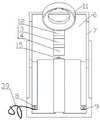
Fig. 1 is a schematic storage view of the present invention.
Fig. 2 is an expanded view of the present invention.
FIG. 3 is a schematic structural view of the left lift cylinder of the present invention.
FIG. 4 is a schematic structural view of the right lift cylinder of the present invention.
Fig. 5 is a schematic view of the installation of the upper and lower connecting rods of the present invention.
Fig. 6 is a schematic sectional structure view of the right protective sleeve of the present invention.
In the figure: 1. a left lifting cylinder, 2, a left visual window, 3, a left wire pressing seat, 4, a left wire pressing bolt, 5, a permanent magnet, 6, a right lifting cylinder, 7, a right visual window, 8, a right wire pressing seat, 9, a right wire pressing bolt, 10, a metal sheet, 11, a sponge ring, 12, an infrared sensor, 13, a battery box, 14, an ultrasonic generator, 15, a button switch, 16, a handle, 17, a transmission part, 18, a left protective cylinder, 19, a left dovetail groove, 20, a first positioning hole, 21, a second positioning hole, 22, a left fixed pulley, 23, a right protective cylinder, 24, a right dovetail groove, 25, a third positioning hole, 26, a fourth positioning hole, 27, a right fixed pulley, 28, a sponge pad, 29, a connecting part, 30, an upper connecting rod, 31, an upper wire pressing seat, 32, an upper wire pressing bolt, 33, a first spring pin, 34, a third spring pin, 35, a lower connecting rod, 36, a second spring pin, 37. a fourth spring pin 38, a left steel wire rope 39 and a right steel wire rope.
Detailed Description
The invention is explained in further detail below with reference to the figures and the specific embodiments.
As shown in fig. 1-6, a convenient chair with a protection function comprises a left lifting cylinder 1, a left visual window 2, a left pressing line seat 3, a left pressing line bolt 4, a permanent magnet 5, a right lifting cylinder 6, a right visual window 7, a right pressing line seat 8, a right pressing line bolt 9, a metal sheet 10, a sponge ring 11, an infrared sensor 12, a battery box 13, an ultrasonic generator 14, a button switch 15, a handle 16 and a transmission part 17, wherein the front and the back of the left lifting cylinder 1 are respectively fixed with a vertical left visual window 2, the front and the back of the left lifting cylinder 1 are respectively fixed with a horizontal left pressing line seat 3, the middle parts of the two left pressing line seats 3 are respectively in threaded connection with a vertical left pressing line bolt 4, the front and the back ends of the inner wall of the left lifting cylinder 1 are respectively fixed with a horizontal permanent magnet 5, the right part of the left lifting cylinder 1 is slidably inserted with a horizontal right lifting cylinder 6, the front and the back of the right lifting cylinder 6 are respectively fixed with a vertical right visual window 7, a horizontally right wire pressing seat 8 is respectively fixed on the front portion and the rear portion of the right lifting cylinder 6, two vertical right wire pressing bolts 9 are respectively in threaded connection with the middle of the right wire pressing seat 8, a horizontal metal sheet 10 is respectively fixed on the front portion and the rear portion of the right lifting cylinder 6, a horizontal sponge ring 11 is fixed on the top end of the inner wall of the right lifting cylinder 6, a vertical infrared sensor 12, a battery box 13, an ultrasonic generator 14 and a button switch 15 are sequentially fixed on the top end of the inner wall of the right lifting cylinder 6 from left to right, a vertical handle 16 is respectively hinged on the left portion of the left lifting cylinder 1 and the right portion of the right lifting cylinder 6, and a transmission portion 17 is jointly installed inside the left lifting cylinder 1 and inside the right lifting cylinder 6.
The transmission part 17 comprises a left protection barrel 18, a left dovetail groove 19, a first positioning hole 20, a second positioning hole 21, a left fixed pulley 22, a right protection barrel 23, a right dovetail groove 24, a third positioning hole 25, a fourth positioning hole 26, a right fixed pulley 27, a spongy cushion 28 and a connecting part 29, wherein the lower part of the left lifting barrel 1 is slidably connected with the vertical left protection barrel 18, the left part of the left protection barrel 18 is provided with a vertical left dovetail groove 19, the left protection barrel 18 is slidably connected with the left lifting barrel 1 through the left dovetail groove 19, the upper part of the left protection barrel 18 is provided with a plurality of vertical first positioning holes 20, the middle part of the left protection barrel 18 is provided with a plurality of vertical second positioning holes 21, the left part of the left protection barrel 18 is rotatably connected with two vertical left fixed pulleys 22, the lower part of the right lifting barrel 6 is slidably connected with a vertical right protection barrel 23, the right part of the right protection barrel 23 is provided with a vertical right dovetail groove 24, the right protection section of thick bamboo 23 is through right dovetail 24 and a right lift section of thick bamboo 6 looks sliding connection, a plurality of vertical No. three locating holes 25 have been run through on a right side lift section of thick bamboo 6 upper portion, a plurality of vertical No. four locating holes 26 have been run through in the middle part of a right side protection section of thick bamboo 23, a right side protection section of thick bamboo 23 right part is rotated and is connected with two vertical right fixed pulleys 27, a left side protection section of thick bamboo 18 and a right side protection section of thick bamboo 23 lower part are fixed with a vertical foam-rubber cushion 28 respectively, install a connecting portion 29 in a left side protection section of thick bamboo 18 and the right side protection section of thick bamboo 23 jointly.
The connecting part 29 comprises an upper connecting rod 30, an upper wire pressing seat 31, an upper wire pressing bolt 32, a first spring pin 33, a third spring pin 34, a lower connecting rod 35, a second spring pin 36 and a fourth spring pin 37, the left protective barrel 18 is in sliding connection with the right protective barrel 23, the upper parts of the left protective barrel 18 and the right protective barrel 23 are in sliding connection with two horizontal upper connecting rods 30 together, the left and right parts of the two upper connecting rods 30 are respectively fixed with a vertical upper wire pressing seat 31, the middle part of each upper wire pressing seat 31 is respectively in threaded connection with a horizontal upper wire pressing bolt 32, the left parts of the two upper connecting rods 30 are respectively provided with two vertical first spring pins 33, the right parts of the two upper connecting rods 30 are respectively provided with two vertical third spring pins 34, the middle parts of the left protective barrel 18 and the right protective barrel 23 are respectively in sliding connection with two horizontal lower connecting rods 35 together, the left parts of the two lower connecting rods 35 are respectively provided with two vertical second spring pins 36, two vertical four-number spring pins 37 are respectively arranged at the right parts of the two lower connecting rods 35.
Two left wire ropes 38 are fastened in the left wire holder 3 through two left wire pressing bolts 4, two left wire ropes 38 are fastened in the upper wire holder 31 at the left part of the two upper connecting rods 30 through the upper wire pressing bolts 32 after passing through the upper part of the left fixed pulley 22, two right wire ropes 39 are fastened in the two right wire holder 8 through two right wire pressing bolts 9, two right wire ropes 39 are fastened in the upper wire holder 31 at the right part of the two upper connecting rods 30 through the upper wire pressing bolts 32 after passing through the upper part of the right fixed pulley 27, the two permanent magnets 5 can be magnetically adsorbed with the two metal sheets 10, the top end of the right protective cylinder 23 can press the button switch 15, each first spring pin 33 can be fastened with each first positioning hole 20, each second spring pin 36 can be fastened with each second positioning hole 21, each third spring pin 34 can be fastened with each third positioning hole 25, each four-number spring pin 37 can be buckled with each four-number positioning hole 26.
The working principle of the invention is as follows: when earthquake disasters occur, the two handles 16 are manually pulled horizontally, so that the left protection cylinder 18 and the right protection cylinder 23 drive the left lifting cylinder 1 and the right lifting cylinder 6 to slide reversely along the upper connecting rod 30 and the lower connecting rod 35, while the left protection cylinder 18 and the right protection cylinder 23 drive the left lifting cylinder 1 and the right lifting cylinder 6 to slide reversely along the upper connecting rod 30 and the lower connecting rod 35, each first spring pin 33 can be buckled with each first positioning hole 20, each second spring pin 36 can be buckled with each second positioning hole 21, each third spring pin 34 can be buckled with each third positioning hole 25, each fourth spring pin 37 can be buckled with each fourth positioning hole 26, thereby realizing the position limitation of the upper connecting rod 30 and the lower connecting rod 35, and in the position limitation process of the upper connecting rod 30 and the lower connecting rod 35, due to the traction of the left steel wire rope 38 and the right steel wire rope 39, the left lifting cylinder 1 and the right lifting cylinder 6 can be lifted synchronously and slide reversely, so that the space formed by the left protective cylinder 18, the right protective cylinder 23, the left lifting cylinder 1 and the right lifting cylinder 6 is enlarged, the device can be worn on the head of a student, the sponge ring 11 is attached to the top of the head of the student, the head and the cervical vertebra of the student are protected sufficiently, the sponge cushion 28 can be buckled on the shoulder of the student, the arm swing of the student is facilitated, the falling caused by the fact that the arm cannot swing is prevented, the probability of the stepping event is reduced, the left visual window 2 and the right visual window 7 can guarantee the visual field of the student, and meanwhile, the right protective cylinder 23 releases the pressing of the button switch 15, so that the infrared sensor 12 and the ultrasonic generator 14 can be powered on and work, the vital signs of the student can be detected through the infrared sensor 12, and send different signals with the information of vital signs through supersonic generator 14 simultaneously to even make even take place to bury the accident, also can make things convenient for subsequent rescue, and permanent magnet 5 can carry out magnetic adsorption with two sheetmetals 10, thereby can guarantee that this device can regard as the stool to use when not expanding, has made things convenient for student's daily use and quick taking when the earthquake, and has prevented the unexpected of this device again simultaneously and has expanded.
The foregoing is a preferred embodiment of the present invention, and it will be apparent to those skilled in the art that variations, modifications, substitutions and alterations can be made in the embodiment without departing from the principles and spirit of the invention.
Claims (1)
1. The utility model provides a convenient chair that has protect function, includes a left side lift section of thick bamboo (1), left visual window (2), left line ball seat (3), left line ball bolt (4), permanent magnet (5), a right side lift section of thick bamboo (6), right visual window (7), right line ball seat (8), right line ball bolt (9), sheetmetal (10), sponge ring (11), infrared sensor (12), battery case (13), supersonic generator (14), button switch (15), handle (16), drive disk assembly (17), its characterized in that: a vertical left visual window (2) is respectively fixed at the front and the rear parts of the left lifting cylinder (1), a horizontal left wire pressing seat (3) is respectively fixed at the front and the rear parts of the left lifting cylinder (1), a vertical left wire pressing bolt (4) is respectively in threaded connection with the middle parts of the two left wire pressing seats (3), a horizontal permanent magnet (5) is respectively fixed at the front and the rear ends of the inner wall of the left lifting cylinder (1), a horizontal right lifting cylinder (6) is in sliding insertion connection with the right part of the left lifting cylinder (1), a vertical right visual window (7) is respectively fixed at the front and the rear parts of the right lifting cylinder (6), a horizontal right wire pressing seat (8) is respectively fixed at the front and the rear parts of the right lifting cylinder (6), a vertical right wire pressing bolt (9) is respectively in threaded connection with the middle parts of the two right wire pressing seats (8), a horizontal metal sheet (10) is respectively fixed at the front and the rear ends of the right lifting cylinder (6), a horizontal sponge ring (11) is fixed at the top end of the inner wall of the right lifting cylinder (6), a vertical infrared sensor (12), a battery box (13), an ultrasonic generator (14) and a button switch (15) are sequentially fixed at the top end of the inner wall of the right lifting cylinder (6) from left to right, a vertical handle (16) is respectively hinged at the left part of the left lifting cylinder (1) and the right part of the right lifting cylinder (6), and a transmission part (17) is jointly installed inside the left lifting cylinder (1) and the right lifting cylinder (6);
the transmission part (17) comprises a left protective cylinder (18), a left dovetail groove (19), a first positioning hole (20), a second positioning hole (21), a left fixed pulley (22), a right protective cylinder (23), a right dovetail groove (24), a third positioning hole (25), a fourth positioning hole (26), a right fixed pulley (27), a sponge pad (28) and a connecting part (29), wherein the lower part of the left lifting cylinder (1) is connected with a vertical left protective cylinder (18) in a sliding manner, the left part of the left protective cylinder (18) is provided with a vertical left dovetail groove (19), the left protective cylinder (18) is connected with the left lifting cylinder (1) in a sliding manner through the left dovetail groove (19), the upper part of the left protective cylinder (18) penetrates through the vertical first positioning holes (20), the middle part of the left protective cylinder (18) penetrates through the vertical second positioning holes (21), and the left part of the left protective cylinder (18) is connected with the two vertical left fixed pulleys (22) in a rotating manner, the lower part of the right lifting cylinder (6) is connected with a vertical right protection cylinder (23) in a sliding mode, a vertical right dovetail groove (24) is formed in the right part of the right protection cylinder (23), the right protection cylinder (23) is connected with the right lifting cylinder (6) in a sliding mode through the right dovetail groove (24), a plurality of vertical third positioning holes (25) penetrate through the upper part of the right lifting cylinder (6), a plurality of vertical fourth positioning holes (26) penetrate through the middle part of the right protection cylinder (23), the right part of the right protection cylinder (23) is connected with two vertical right fixed pulleys (27) in a rotating mode, a vertical sponge pad (28) is fixed to the lower parts of the left protection cylinder (18) and the right protection cylinder (23) respectively, and a connecting part (29) is installed in the left protection cylinder (18) and the right protection cylinder (23) together;
the connecting part (29) comprises an upper connecting rod (30), an upper wire pressing seat (31), an upper wire pressing bolt (32), a first spring pin (33), a third spring pin (34), a lower connecting rod (35), a second spring pin (36) and a fourth spring pin (37), the left protective cylinder (18) is in sliding connection with the right protective cylinder (23), the upper parts of the left protective cylinder (18) and the right protective cylinder (23) are jointly in sliding connection with two horizontal upper connecting rods (30), the left part and the right part of each upper connecting rod (30) are respectively fixed with a vertical upper wire pressing seat (31), the middle part of each upper wire pressing seat (31) is respectively in threaded connection with a horizontal upper wire pressing bolt (32), the left part of each upper connecting rod (30) is respectively provided with two vertical first spring pins (33), the right part of each upper connecting rod (30) is respectively provided with two vertical third spring pins (34), the middle parts of the left protective barrel (18) and the right protective barrel (23) are jointly connected with two horizontal lower connecting rods (35) in a sliding mode, two vertical second spring pins (36) are mounted on the left parts of the two lower connecting rods (35) respectively, and two vertical fourth spring pins (37) are mounted on the right parts of the two lower connecting rods (35) respectively;
two left wire ropes (38) are fastened in the two left wire pressing seats (3) through two left wire pressing bolts (4), the two left wire ropes (38) are fastened in the upper wire pressing seats (31) at the left parts of the two upper connecting rods (30) through upper wire pressing bolts (32) after passing through the upper parts of the left fixed pulleys (22), two right wire ropes (39) are fastened in the two right wire pressing seats (8) through two right wire pressing bolts (9), the two right wire ropes (39) are fastened in the upper wire pressing seats (31) at the right parts of the two upper connecting rods (30) through upper wire pressing bolts (32) after passing through the upper parts of the right fixed pulleys (27), the two permanent magnets (5) can be magnetically adsorbed with the two metal sheets (10), the top ends of the right protective cylinders (23) can press the button switches (15), each spring pin (33) can be buckled with each first spring pin (20), each second spring pin (36) can be buckled with each second positioning hole (21), each third spring pin (34) can be buckled with each third positioning hole (25), and each fourth spring pin (37) can be buckled with each fourth positioning hole (26).
Priority Applications (1)
| Application Number | Priority Date | Filing Date | Title |
|---|---|---|---|
| CN202110471276.8A CN113040552B (en) | 2021-04-29 | 2021-04-29 | Convenient chair with protection function |
Applications Claiming Priority (1)
| Application Number | Priority Date | Filing Date | Title |
|---|---|---|---|
| CN202110471276.8A CN113040552B (en) | 2021-04-29 | 2021-04-29 | Convenient chair with protection function |
Publications (2)
| Publication Number | Publication Date |
|---|---|
| CN113040552A CN113040552A (en) | 2021-06-29 |
| CN113040552B true CN113040552B (en) | 2022-07-05 |
Family
ID=76517785
Family Applications (1)
| Application Number | Title | Priority Date | Filing Date |
|---|---|---|---|
| CN202110471276.8A Active CN113040552B (en) | 2021-04-29 | 2021-04-29 | Convenient chair with protection function |
Country Status (1)
| Country | Link |
|---|---|
| CN (1) | CN113040552B (en) |
Citations (5)
| Publication number | Priority date | Publication date | Assignee | Title |
|---|---|---|---|---|
| GB1379784A (en) * | 1971-07-22 | 1975-01-08 | Stanley Aviation Corp | Escape apparatus |
| CN101617892A (en) * | 2008-07-04 | 2010-01-06 | 吴正德 | Lifting table |
| CN204232683U (en) * | 2014-12-10 | 2015-04-01 | 四川农业大学 | The Leisure Sofa that can play a protective role when natural calamity occurs |
| JP2018111372A (en) * | 2017-01-11 | 2018-07-19 | カヤバ システム マシナリー株式会社 | Lifting device |
| CN211885001U (en) * | 2020-03-30 | 2020-11-10 | 河北天振工程技术有限公司 | A home escape device |
Family Cites Families (2)
| Publication number | Priority date | Publication date | Assignee | Title |
|---|---|---|---|---|
| US8985693B2 (en) * | 2011-11-02 | 2015-03-24 | The Boeing Company | Transport vehicle upright sleep support system |
| US11766101B2 (en) * | 2015-04-23 | 2023-09-26 | Mark Ferrara | Personal protective covering device |
-
2021
- 2021-04-29 CN CN202110471276.8A patent/CN113040552B/en active Active
Patent Citations (5)
| Publication number | Priority date | Publication date | Assignee | Title |
|---|---|---|---|---|
| GB1379784A (en) * | 1971-07-22 | 1975-01-08 | Stanley Aviation Corp | Escape apparatus |
| CN101617892A (en) * | 2008-07-04 | 2010-01-06 | 吴正德 | Lifting table |
| CN204232683U (en) * | 2014-12-10 | 2015-04-01 | 四川农业大学 | The Leisure Sofa that can play a protective role when natural calamity occurs |
| JP2018111372A (en) * | 2017-01-11 | 2018-07-19 | カヤバ システム マシナリー株式会社 | Lifting device |
| CN211885001U (en) * | 2020-03-30 | 2020-11-10 | 河北天振工程技术有限公司 | A home escape device |
Also Published As
| Publication number | Publication date |
|---|---|
| CN113040552A (en) | 2021-06-29 |
Similar Documents
| Publication | Publication Date | Title |
|---|---|---|
| CN113040552B (en) | Convenient chair with protection function | |
| CN206777728U (en) | A kind of rehabilitation department rehabilitation exercise device | |
| CN201861200U (en) | Earthquake refuge bed | |
| CN201253028Y (en) | Combined shockproof bedstead | |
| CN117125257B (en) | An attitude control system for parachute training equipment | |
| CN208350750U (en) | A kind of mine hole gas detecting device | |
| CN215068781U (en) | Training device for flight attendant etiquette teaching | |
| CN212679984U (en) | Recovered branch of academic or vocational study is with arm rehabilitation training device | |
| CN214124536U (en) | Effectual control box of shock attenuation | |
| CN202739371U (en) | Quake-proof bed with lifting springs | |
| CN2582665Y (en) | Butterfly chest expander | |
| CN219963854U (en) | Rehabilitation training device convenient to equipment | |
| CN218106667U (en) | Dorsal muscle trainer with protection function | |
| CN205539535U (en) | Human safety check device | |
| CN216388432U (en) | A railway train dispatching virtual reality equipment for railway staff training | |
| CN220989569U (en) | Upper limb strength training device with protective structure | |
| CN218330241U (en) | Environmental noise detection device with prevent falling function | |
| CN210483192U (en) | Multipurpose antidetonation escape device | |
| CN113229619A (en) | Earthquake safety desk with adjustable | |
| CN212972380U (en) | Lifting device for office chair armrest | |
| CN211237248U (en) | Intelligent safety experience system and walking sliding simulation experience device thereof | |
| CN213416197U (en) | Adjustable detection platform for offshore oil drilling device | |
| CN217430741U (en) | An intelligent fire inspection cabinet | |
| CN213633788U (en) | Auxiliary equipment for fire-fighting detection | |
| CN221220306U (en) | Window structure and burglary-resisting door |
Legal Events
| Date | Code | Title | Description |
|---|---|---|---|
| PB01 | Publication | ||
| PB01 | Publication | ||
| SE01 | Entry into force of request for substantive examination | ||
| SE01 | Entry into force of request for substantive examination | ||
| TA01 | Transfer of patent application right | ||
| TA01 | Transfer of patent application right |
Effective date of registration: 20220531 Address after: 313300 east side of Lingfeng Avenue, Anji Economic Development Zone, Huzhou City, Zhejiang Province Applicant after: Anji Jinrun Furniture Co.,Ltd. Address before: 277 200 No. 18 Shanting New Town Construction Road, Zaozhuang City, Shandong Province Applicant before: SHANDONG LIYU FURNITURE Co.,Ltd. |
|
| GR01 | Patent grant | ||
| GR01 | Patent grant |