CN113016337B - Radix ophiopogonis seedling cutting and fruit picking system and method - Google Patents
Radix ophiopogonis seedling cutting and fruit picking system and method Download PDFInfo
- Publication number
- CN113016337B CN113016337B CN202110273670.0A CN202110273670A CN113016337B CN 113016337 B CN113016337 B CN 113016337B CN 202110273670 A CN202110273670 A CN 202110273670A CN 113016337 B CN113016337 B CN 113016337B
- Authority
- CN
- China
- Prior art keywords
- seedling
- fruit picking
- cutting
- radix ophiopogonis
- root
- Prior art date
- Legal status (The legal status is an assumption and is not a legal conclusion. Google has not performed a legal analysis and makes no representation as to the accuracy of the status listed.)
- Active
Links
Images


Classifications
-
- A—HUMAN NECESSITIES
- A01—AGRICULTURE; FORESTRY; ANIMAL HUSBANDRY; HUNTING; TRAPPING; FISHING
- A01D—HARVESTING; MOWING
- A01D45/00—Harvesting of standing crops
-
- B—PERFORMING OPERATIONS; TRANSPORTING
- B26—HAND CUTTING TOOLS; CUTTING; SEVERING
- B26D—CUTTING; DETAILS COMMON TO MACHINES FOR PERFORATING, PUNCHING, CUTTING-OUT, STAMPING-OUT OR SEVERING
- B26D1/00—Cutting through work characterised by the nature or movement of the cutting member or particular materials not otherwise provided for; Apparatus or machines therefor; Cutting members therefor
- B26D1/01—Cutting through work characterised by the nature or movement of the cutting member or particular materials not otherwise provided for; Apparatus or machines therefor; Cutting members therefor involving a cutting member which does not travel with the work
- B26D1/04—Cutting through work characterised by the nature or movement of the cutting member or particular materials not otherwise provided for; Apparatus or machines therefor; Cutting members therefor involving a cutting member which does not travel with the work having a linearly-movable cutting member
- B26D1/06—Cutting through work characterised by the nature or movement of the cutting member or particular materials not otherwise provided for; Apparatus or machines therefor; Cutting members therefor involving a cutting member which does not travel with the work having a linearly-movable cutting member wherein the cutting member reciprocates
- B26D1/08—Cutting through work characterised by the nature or movement of the cutting member or particular materials not otherwise provided for; Apparatus or machines therefor; Cutting members therefor involving a cutting member which does not travel with the work having a linearly-movable cutting member wherein the cutting member reciprocates of the guillotine type
Abstract
A fruit picking system and method for cutting seedlings of radix ophiopogonis comprises a lower conveying chain and an upper conveying chain, a conveying area is formed between the lower conveying chain and the upper conveying chain, a fruit picking device is arranged on one side of the conveying area and comprises a fruit picking mechanism group, the fruit picking mechanism group comprises two fruit picking mechanisms which are arranged up and down, the fruit picking mechanism comprises a control mechanism and a cutter group, the cutter group of the two fruit picking mechanisms is driven by the control mechanism to move along a rectangular motion track and sequentially passes through a cutting section and a clamping section of the rectangular motion track, the two cutter groups are combined to cut the roots of the radix ophiopogonis in the cutting section, and the two cutter groups are combined to clamp the roots of the cut radix ophiopogonis in the clamping section. The invention realizes a separation mode combining cutting and clamping, can further separate the root of the tuber by clamping and pulling after a cut is formed by cutting under the condition that the root of the tuber and the tuber of dwarf lilyturf are not easy to cut, and obviously improves the fruit picking efficiency and the fruit picking rate of dwarf lilyturf.
Description
Technical Field
The invention relates to the field of agricultural machinery, in particular to a system and a method for cutting and picking dwarf lilyturf tuber seedlings.
Background
Ophiopogon japonicus, also known as Ophiopogon japonicus, Zostera marina, Ophiopogon japonicus, and Ophiopogon japonicus, is a perennial evergreen herb of Ophiopogon genus of Liliaceae family. The fibrous root of ophiopogon root is thicker and the top or middle part of the root is often expanded to become spindle-shaped small fleshy mass. Radix Ophiopogonis tuber can be used as medicine, and has effects of improving immunity, enhancing pituitary adrenal cortex system function, and lowering blood sugar.
In order to solve the problem of picking fruits or cutting seedlings manually and improve picking efficiency, the prior art is provided with an ophiopogon root cutting and picking machine for automatically picking root tubers of ophiopogon roots or automatically cutting seedlings. Patent CN211153742U discloses a fruit picking machine for radix ophiopogonis, which is characterized in that a plurality of glue columns arranged on different surfaces of a rotating plate are used for sequentially beating the root tuber of the root of radix ophiopogonis, the direction of the regularly arranged glue columns is consistent with the direction of fibrous roots of the radix ophiopogonis in the rotating and beating process, and the root tuber is conveniently separated on the premise of keeping the fibrous roots complete. The device can only realize the fruit picking process in the moving process of the radix ophiopogonis, and only the roots of the radix ophiopogonis blocks are separated in the fruit picking process in a beating mode, so that the separation mode is single, and the separation effect is poor. Patent CN112020989A discloses a fruit and seedling picking and cutting machine for radix ophiopogonis, which utilizes a fruit cutting blade and a leaf cutting blade arranged on the side surface of a conveying chain to simultaneously cut the root hairs and the tip leaves of the whole plants of the radix ophiopogonis seedlings in the conveying process of the radix ophiopogonis, and improves the processing efficiency to a certain extent by combining a seedling cutting process and a fruit picking process. However, the method of cutting with the rotary knife in the fruit picking and seedling cutting machine still has the problem of single separation method, and during the cutting process, the root tuber or the tip leaf which is not easy to be separated easily moves to the same direction as the cutting direction to remove part of the acting force of the rotary knife, so that the separation effect is poor.
Disclosure of Invention
The invention aims to provide a dwarf lilyturf tuber seedling cutting and fruit picking system and a dwarf lilyturf tuber seedling cutting and fruit picking method, which aim to solve the problems of low dwarf lilyturf tuber fruit picking efficiency and fruit picking rate caused by single separation mode and easy removal of acting force applied for separation of a seedling cutting and fruit picking machine in the prior art.
The invention is realized by the following technical scheme:
the utility model provides a tuber of dwarf lilyturf cuts seedling and picks fruit system, includes down conveying chain and last conveying chain, it constitutes the transport area territory that is used for the centre gripping to carry the wheat seedling to carry down between conveying chain and the last conveying chain, one side of conveying area territory is provided with picks the fruit device, it includes that at least a set of fruit picking mechanism group to pick the fruit device, it includes two fruit picking mechanisms that upper and lower set up to pick fruit mechanism group, it includes control mechanism and cutter group to pick fruit mechanism, two cutter groups of picking fruit mechanism are used for removing along the rectangle movement path under control mechanism's drive, and the section is got with pressing from both sides to the cutting section through the rectangle movement path in proper order the cutting section, the piece root of cutting tuber of dwarf lilyturf is got to two cutter groups and the piece root portion after the cutting is got to the clamp.
In the technical scheme, the same as the patent CN112020989A, the dwarf lilyturf tuber seedling cutting and fruit picking mechanism comprises a conveying unit which is composed of an upper conveying chain and a lower conveying chain and is used for clamping and conveying wheat seedlings. In the process of conveying wheat seedlings, fruit picking procedures and seedling cutting procedures are carried out simultaneously at two ends of the wheat seedlings, namely the root parts and the seedling tip parts, so that the processing efficiency of radix ophiopogonis is improved.
Different from the prior art, the technical scheme is that the fruit picking device and/or the seedling cutting device are/is designed to separate the two ends of the radix ophiopogonis from the main body by adopting a separation mode combining cutting and clamping in the fruit picking process and the seedling cutting process, so that the separation effect and the separation rate are remarkably improved.
Specifically, pluck fruit device and include the shell, be provided with feed inlet and collection mouth on the shell, wherein, the feed inlet is used for plucking the cutter group of fruit mechanism group and stretches into or stretch out the shell in order to surely get the root of a piece and bring the root of a piece into the shell, collects the mouth and is used for discharging the interior accumulational root of a piece of shell and collects to the shell outside.
One or more fruit picking mechanism sets are arranged in the shell. The number of the fruit picking mechanism groups can be adjusted according to the length of the fruit picking mechanism groups and the length of the conveying area. The fruit picking mechanism group comprises an upper fruit picking mechanism and a lower fruit picking mechanism, the upper and lower fruit picking mechanisms have the same structure and both comprise a control mechanism and a cutter group. The control mechanism is used for driving the cutter group to move along a preset rectangular motion track.
The rectangular motion track comprises a cutting section, a clamping section, a vertical section and a horizontal section which are connected in sequence. When fruits need to be picked, the control mechanism drives the cutter sets to move along the vertical section and the horizontal section, after the cutter sets move to the outer part of the shell through the feeding port, the cutter sets enter the vertical cutting section, the upper cutter set and the lower cutter set move oppositely, the upper cutter set moves to the lower limit of the stroke of the cutting section, and when the lower cutter set moves to the upper limit of the stroke of the cutting section, the two cutter sets combine to cut the root of the root and stem of the dwarf lilyturf at the root and stem joint, or cut cuts are formed at the root and stem joint or on the root of the root and stem. The two sets of tools that are then mated together move along the horizontal gripping section towards the interior of the housing. In the process of moving along the clamping section, the cutter group clamps the root of the block and pulls the root of the block to the direction far away from the radix ophiopogonis, so that further pulling force is provided after cutting to ensure that the root of the block which is not cut and only has a cut is separated from the main body, and after separation, the root of the block enters the shell along with the cutter group to be collected. And then, the upper and lower cutter groups move back to back along the vertical section, enter the horizontal section and move out of the shell for next cutting and clamping.
In order to realize the matching of the cutter groups, the moving directions of the upper cutter group and the lower cutter group are opposite, for example, one rectangular motion track is clockwise moving, and the other is anticlockwise moving. In some embodiments, the movement path of the tool set may also be in other shapes, such as a circle, a triangle, a polygon, or an irregular figure, as long as the tool set includes a cutting section and a clamping section which are connected in sequence.
Compared with the separation mode of beating or cutting in the prior art, the separation mode of combining cutting and clamping is realized by using the control mechanism of the fruit picking mechanism group to drive the cutter group to move along the rectangular motion track and sequentially pass through the cutting section and the clamping section, the root of the tuber can be clamped and conveyed into the shell after being cut under the condition that the joint of the root of the tuber and the tuber of dwarf lilyturf is easy to cut, and the root of the tuber can be further separated by clamping and pulling after the cut is formed under the condition that the joint of the root of the tuber and the tuber of dwarf lilyturf has high toughness and a cutting point is positioned on the root of the tuber or other conditions that the cut is difficult to cut, so that the fruit picking efficiency and the fruit picking rate of dwarf lilyturf are remarkably improved; in addition, the upper cutter group and the lower cutter group are mutually supported in the matching process, the situation that the root of the block is unloaded by moving towards the opposite direction in the process of being flapped or cut by the rotary cutter can be effectively avoided, and the fruit picking effect is further improved.
In some embodiments, the system further comprises a seedling cutting device, the seedling cutting device is located at the opposite side of the fruit picking device, and the seedling cutting device is used for performing a seedling cutting process on the radix ophiopogonis. The seedling cutting device can adopt a cutting mechanism in the prior art, such as a leaf cutting blade in CN112020989A, and can also adopt any structure of the fruit picking device as the seedling cutting device, so that in the seedling cutting process, the seedling tip part of the radix ophiopogonis is separated from the main body in a separation mode combining cutting and clamping.
In some embodiments, when the radix ophiopogonis piles are located in the conveying area, the upper surface and the lower surface of the radix ophiopogonis piles are pressed by the conveying chains and move towards the discharging end along with the movement of the upper conveying chain and the lower conveying chain under the action of the pressing. Furthermore, rotary pressing pieces are arranged on two sides of the conveying mechanism and used for pressing the height of the radix ophiopogonis piles on the lower conveying chain to be smaller than that of the conveying area. The rotary pressing member is located between the conveying area and the housing. Before entering the conveying area, the rotating pressing piece in a rotating state downwards presses two ends of the radix ophiopogonis by utilizing the blades of the rotating pressing piece, so that the overall height of the radix ophiopogonis piles is reduced to be lower than that of the conveying area, and the radix ophiopogonis piles can be enabled to enter the conveying area smoothly. After entering the conveying area, the radix ophiopogonis piles are clamped by the conveying chains to move under the action of the extrusion force of the upper conveying chain and the lower conveying chain in the height recovery process.
As a preferable structure of the control mechanism of the invention, the control mechanism comprises a first driving device and a first guide rod, a sliding block is slidably arranged on the first guide rod, a second guide rod perpendicular to the first guide rod is arranged on the sliding block, a connecting rod is slidably arranged on the second guide rod and connected to the cutter set, a push rod is hinged to the connecting rod, a steering block is sleeved outside the push rod and connected with the output end of the first driving device, and a first spring positioned between the steering block and the connecting rod is sleeved outside the push rod. In this technical solution, the driving device of the control mechanism is a first driving device. The output end of the first driving device is connected with a steering block and can drive the steering block to rotate. A guide through hole is formed in the steering block, and a push rod arranged in the guide through hole can move along the guide through hole. One end of the push rod is hinged to the connecting rod, so that an included angle between the push rod and the connecting rod can be changed along with different positions of the connecting rod on the rectangular track, the hinge mode of the push rod and the connecting rod can be realized in a mode of matching pin holes and pin shafts, for example, the push rod and the connecting rod are respectively provided with the pin holes, and the hinge is realized through the pin shafts movably inserted into the pin holes. The first guide bar and the second guide bar are guide members that ensure the links to move along a rectangular trajectory. Specifically, first guide bar level sets up, and the second guide bar of the first guide bar of perpendicular to passes through slider and first guide bar sliding connection, simultaneously, offer on the connecting rod with second guide bar external diameter assorted through-hole to make the connecting rod can follow the second guide bar and remove, push away the push rod at the piece that turns to and drive the connecting rod along the rectangular motion orbit of first guide bar, second guide bar removal in-process realization connecting rod. In the technical scheme, still be provided with first spring on the push rod, in the connecting rod removal process, the distance constantly change between push rod hinged end to the piece that turns to, when turning to the piece and moving trajectory distance when far away region, the distance of push rod hinged end to the piece that turns to increases, the tensile energy release of spring this moment, otherwise, when the region that the distance is close is passed through, the distance shortens, spring compression energy storage this moment, when first spring is when switching between energy storage and energy release, can make cutter group when getting the section through cutting section and clamp, can apply the non-invariable effort that increases gradually or reduces gradually to the tuber of dwarf lilyturf, compare in the invariable effort among the prior art, can produce higher impulsive force in order to further improve the separation effect of root of tuber.
In some embodiments, the turning blocks may be concentrically arranged, i.e. arranged at the center of the rectangular motion track, or may be eccentrically arranged. Specifically, the steering block is eccentrically arranged in the rectangular motion track, and the steering block is close to the lower end of the second guide rod.
As a preferred embodiment of the eccentric arrangement of the rectangular motion track, the steering block is close to the lower end of the second guide rod and one end of the first guide rod far away from the feed inlet. In the technical scheme, the steering block is close to an included angle between a vertical section of a rectangular motion track and the clamping section. During operation, get into the cutting section after, the vertical decurrent removal in-process of cutter unit, because turn to the piece far away apart from the cutting section, first spring is in natural state or extension state, and the influence that the cutter unit receives first spring is little, perhaps receives the influence of releasing energy of certain degree, and two cutter units can be normal or accelerate and move in opposite directions to improve the effort of cutter unit in the rhizome junction, reinforcing cutting effect. After the cutting is accomplished, press from both sides the in-process that gets the section and remove, along with turn to the piece and press from both sides the distance between the section and shorten gradually, first spring constantly stores energy, and the process of getting is compared in turning to the piece and setting up more slowly with one heart.
As another preferred embodiment of the eccentric arrangement of the rectangular motion track, the steering block is close to the lower end of the second guide rod and one end of the first guide rod close to the feed inlet. In the technical scheme, the steering block is close to an included angle between the cutting section and the clamping section of the rectangular motion track. During operation, get into the cutting section after, the vertical in-process that moves down of cutter group, first spring compress the energy storage earlier gradually and extend gradually after the energy release, when two cutter group contacts, can accelerate relative movement and then improve the effort of cutter group at the rhizome junction, reinforcing cutting effect. Subsequently, after entering the clamping section, the first spring gradually compresses the stored energy and then gradually extends the energy release, and in the energy release stage, the first spring pushes the connecting rod to rapidly move along the clamping section so as to apply gradually increased pulling force and enhance the separation effect. This eccentric structure can realize simultaneously that the spring of cutting section and clamp section releases the ability, utilizes the effort of first spring to exert gradual change's effort to rhizome junction or incision to be favorable to improving the cutting force at the cutting section, and be favorable to improving the pulling force at the section of pressing from both sides, improve the root tuber separation effect remarkably.
Further, the cutter group includes the mounting panel, be provided with a plurality of recesses on the mounting panel side by side, it is provided with second spring and cutter to slide in the recess, the inner wall of second spring coupling cutter and recess. The plurality of grooves arranged on the mounting plate are used for placing the cutters, and the cutters can move along the grooves. The cutter is provided with a second spring which is connected with the groove, so that the cutter can reset to the initial position in the groove after the external force is removed. The second spring not only can reset the cutter, and when pressing from both sides the root tuber portion of getting difficult to separate moreover, the cutter at first keeps motionless, and when the mounting panel removed to vertical section along with the connecting rod, the second spring was elongated gradually and is held power, and the root tuber portion pulling force constantly increases, separates with the tuber of dwarf lilyturf stem immediately after being greater than the threshold value. And by combining the eccentric rectangular motion track, the second spring can quickly finish the force accumulation in the energy releasing process of the first spring, so that the instantaneous impulse force is generated to obviously improve the separation effect.
Further, the cutter includes cutting edge and centre gripping groove, and when upper and lower cutter was cooperated, two upper and lower centre gripping grooves constitute the centre gripping region who is used for the grip block root, the centre gripping region is the toper structure, the internal diameter of toper structure is followed the centre gripping groove and is close to the one end of cutting edge to the direction of the one end that the cutting edge was kept away from to the centre gripping groove and is increased gradually. During the cutting, cutting edge and centre gripping groove remove simultaneously, and the centre gripping groove is used for the centre gripping tuberous root, and the cutting edge is used for cutting the rhizome junction, and the back is accomplished in the cutting, no matter be the junction disconnection or form the incision, the complex cutter all forms the centre gripping region through the centre gripping groove and carries out the centre gripping in order to drag it to get the portion removal along pressing from both sides, realizes getting the separation of getting of ophiopogon root. When two cutters in the clamping section are mutually matched, the upper clamping groove and the lower clamping groove form a conical clamping area, and the inner diameter of the conical clamping area is gradually increased along the direction from the cutting section to the vertical section, so that the root tuber is more easily separated from the stem of the radix ophiopogonis, and the root tuber falls off from the clamping grooves after the cutters are mutually far away.
In some embodiments, a screw is arranged below the fruit picking mechanism group and used for conveying root tubers in the shell to the outside of the shell through the collecting port.
Further, still including arranging the seedling device, arrange the seedling device and include the ascending casing of opening, be provided with the feed inlet on the casing, carry the chain down and extend to in the casing through the feed inlet, be provided with at least two sets of row seedling mechanisms in the casing, adjacent two sets of row seedling mechanisms form row seedling region between, arrange the seedling region and be close to one side of carrying the chain down, arrange seedling mechanism and be used for pushing down the tuber of dwarf lilyturf that falls into row seedling region, make the root of tuber of dwarf lilyturf and the seedling point portion be located respectively carry regional both sides.
In the technical scheme, at least two groups of seedling discharging mechanisms are arranged in the shell, and preferably, the number of the seedling discharging mechanisms is two. A seedling discharging area is formed between the two adjacent groups of seedling discharging mechanisms, the radix ophiopogonis enters the shell through the top opening of the shell and then falls into the seedling discharging area under the action of gravity, all the radix ophiopogonis in the seedling discharging area are pushed down towards the same direction under the pushing of the seedling discharging mechanisms, so that the radix ophiopogonis are orderly stacked on the conveying mechanism, and the root parts and the seedling tip parts of the radix ophiopogonis are respectively positioned at two sides of the conveying area, and the seedling cutting and/or fruit picking procedures of the stacked radix ophiopogonis are convenient to follow-up.
During feeding, the radix ophiopogonis is thrown into the shell from the top end of the shell. After the seedling planting machine enters the shell, the root tuber of the dwarf lilyturf tuber is heavier than the seedling tip part, so that the root tuber is positioned below and the seedling tip part is positioned above under the action of gravity, when the dwarf lilyturf tuber falls into a seedling discharging area between two adjacent groups of seedling discharging mechanisms, the root tuber further moves downwards and falls onto a lower conveying chain below the seedling discharging mechanisms, and the seedling tip part of the dwarf lilyturf tuber is positioned in the seedling discharging area. Then, the seedling discharging mechanism rotates in the same direction to push down the radix ophiopogonis, so that the radix ophiopogonis is orderly stacked on the lower conveying chain.
Through the structure, the characteristics that the mass of the root tuber of dwarf lilyturf root is greater than the mass of the tip part of the dwarf lilyturf root are utilized, deflection of a certain degree can be generated in the falling process of the dwarf lilyturf root in the shell, the tip part of the dwarf lilyturf root is positioned in the seedling discharging area when the dwarf lilyturf root falls on the conveying mechanism, and then the dwarf lilyturf root is pushed by the seedling discharging mechanism to push the dwarf lilyturf root towards one direction, finally the dwarf lilyturf root is orderly stacked on the conveying chain, the tip part and/or the root tuber of the dwarf lilyturf root extend to the outer side of the conveying area, the subsequent dwarf lilyturf root cutting and/or fruit picking procedures are carried out in the conveying process, the dwarf lilyturf root feeding procedure is simplified, automatic seedling discharging is realized, the position of the dwarf lilyturf root on the conveying mechanism is not required to be further adjusted manually, the work load is reduced, and the production efficiency is improved.
As a preferable structure of the seedling arranging mechanism, the seedling arranging mechanism comprises an installation frame fixed on the inner wall of the shell, a second driving device is arranged on the installation frame, the output end of the second driving device is connected with a driving wheel, a seedling arranging chain is meshed on the outer wall of the driving wheel, a plurality of seedling arranging teeth are arranged on the seedling arranging chain, and the seedling arranging teeth are used for pushing down the radix ophiopogonis in the seedling arranging area.
In the technical scheme, the seedling discharging mechanism comprises an annular seedling discharging chain driven by a driving wheel. The ring shape can be a circular ring shape, and can also be other regular or irregular ring structures. The inner wall of the seedling discharging chain is provided with a plurality of tooth grooves, and the tooth grooves are meshed with the gear on the outer wall of the driving wheel, so that the rotating driving wheel is allowed to drive the seedling discharging chain to move. And a plurality of seedling-discharging teeth are arranged on the outer wall of the seedling-discharging chain. When the radix ophiopogonis vertically falls onto the conveying mechanism, the seedling discharging teeth sequentially pass through the seedling discharging area under the driving of the rotating annular chain, and the radix ophiopogonis in the seedling discharging area is pushed down to the moving direction of the seedling discharging teeth. Therefore, the moving direction of the seedling discharging teeth in the seedling discharging area is set to be vertical to the conveying direction of the radix ophiopogonis, and the seedling discharging teeth can push the radix ophiopogonis in the seedling discharging area down along the direction vertical to the conveying direction of the radix ophiopogonis. Further, when the drop point and the seedling discharge area above the drop point are arranged on one side of the lower conveying chain, the root tuber part of the dwarf lilyturf tuber pushed down by the seedling discharge teeth is positioned on the side, and the seedling tip part is positioned on the other side of the lower conveying chain. The seedling arranging structure can continuously push the radix ophiopogonis falling into the seedling arranging area to the same direction, and then the radix ophiopogonis seedlings are orderly stacked on the lower conveying chain.
In some embodiments, two adjacent seedling rows on the same seedling row chain are connected through a hinge. The seedling arranging chain comprises a plurality of seedling arranging teeth, connecting plates are arranged at the bottoms of the seedling arranging teeth, pin holes are formed in the two sides of each connecting plate, and the pin holes penetrate through pin shafts to form hinge connection. Through hinged joint, two adjacent row seedling teeth can relatively deflect certain angle in order to pass through the crooked section of drive wheel.
Further, install the top cap on the top of casing, be provided with feed mechanism on the top cap, feed mechanism's bottom is located arrange the seedling region directly over, feed mechanism is including installing the sleeve on the top cap, be provided with on the telescopic inner wall and place the platform, place the bench and placed the feeder hopper, the top of feeder hopper is located telescopic top, is provided with a plurality of third springs between the outer wall of feeder hopper and the telescopic inner wall, is provided with vibrating motor on the feeder hopper. When the radix ophiopogonis is thrown into the shell through the feeding mechanism, the feeding mechanism can further prolong the falling time of the radix ophiopogonis, so that the radix ophiopogonis has enough time to adjust the falling direction, the number of the radix ophiopogonis with root tuber vertically downward is further increased, and the reliability of the seedling discharging device is improved.
As a preferable structure of the feeding mechanism, the feeding mechanism comprises two parts, namely a sleeve and a feed hopper. Specifically, the bottom end of the feed hopper is placed on the placing table on the inner wall of the sleeve by the top end of the sleeve, and the top end of the feed hopper is located above the sleeve. The feeder hopper is provided with a plurality of third springs on being located the telescopic part, and the telescopic inner wall of third spring coupling and the outer wall of feeder hopper not only can increase the vibration range of feeder hopper, produces the back of rocking of certain range at the relative sleeve of feeder hopper moreover, and the third spring can reset the feeder hopper to initial position. Through above-mentioned structure, after the feeder hopper that the tuber of dwarf lilyturf got into the vibration, the tuber of dwarf lilyturf that is located on the inclined section inner wall of feeder hopper was because the piece root is heavier and constantly adjust the direction in the feeder hopper, got into the sleeve after, the tuber of dwarf lilyturf through preliminary adjustment orientation continues to adjust the orientation at the in-process that falls down, finally, through the dual function of feeder hopper vibration section and sleeve extension section, the tuber root homoenergetic of the overwhelming majority tuber of dwarf lilyturf is vertical down.
The invention also provides a dwarf lilyturf seedling cutting and fruit picking method, which adopts any one of the dwarf lilyturf seedling cutting and fruit picking systems, and comprises the following steps:
conveying the radix ophiopogonis to be processed to the conveying area through a lower conveying chain, wherein two ends of the radix ophiopogonis are respectively positioned at two sides of the conveying area;
the seedling cutting device and the fruit picking device respectively cut two ends of the radix ophiopogonis;
the upper and lower cutter groups of the fruit picking mechanism group of the fruit picking device move along a rectangular motion track, and when the fruit picking mechanism group passes through a cutting section of the rectangular motion track, the two cutter groups are combined and cut the root of the tuber of dwarf lilyturf; and then when the clamping section passes through the rectangular motion track, the two cutters are combined and clamped to clamp the cut root of the tuberous root.
Compared with the prior art, the invention has the following advantages and beneficial effects:
1. according to the invention, the control mechanism of the fruit picking mechanism group is utilized to drive the cutter group to move along the rectangular motion track and sequentially pass through the cutting section and the clamping section, so that a separation mode combining cutting and clamping is realized, the root of the tuber can be clamped and conveyed into the shell after being cut off under the condition that the joint of the root of the tuber and the tuber of dwarf lilyturf is easy to cut off, and the root of the tuber can be further separated by clamping and pulling after a cut is formed under the condition that the joint of the root of the tuber and the tuber of dwarf lilyturf is high in toughness, a cutting point is positioned on the root of the tuber or other conditions that the root of the tuber and the tuber of dwarf lilyturf are difficult to cut off, so that the fruit picking efficiency and the fruit picking rate of dwarf lilyturf are remarkably improved;
2. the upper and lower cutter groups are mutually supported in the matching process, so that the situation that the root of the block is unloaded by moving in the opposite direction in the process of being flapped or cut by the rotary cutter can be effectively avoided, and the fruit picking effect is further improved;
3. the control mechanism can repeatedly store and release energy during the process that the connecting rod moves along the rectangular motion track, so that in the process of switching between energy storage states and energy release states, the cutter group can apply gradually increased or gradually decreased non-constant acting force to the radix ophiopogonis when passing through the cutting section and the clamping section, and compared with the constant acting force in the prior art, higher impulsive force can be generated to further improve the separation effect of the root tuber;
4. the steering block is eccentrically arranged at the corner of the rectangular motion track, which is close to the position between the cutting section and the clamping section, so that the spring energy release of the cutting section and the clamping section can be realized simultaneously, the acting force of the first spring is utilized to apply gradually changed acting force to the root-stem connecting part or the cut, the cutting force is favorably improved at the cutting section, the pulling force is favorably improved at the clamping section, and the root separating effect is obviously improved;
5. according to the cutter set, the groove is formed in the mounting plate, the second spring connected with the cutter is arranged in the groove, the cutter can be reset, the cutter is firstly kept still when the root tuber which is not easy to separate is clamped, the second spring is gradually stretched and stores force when the mounting plate moves to the vertical section along with the connecting rod, the tension force borne by the root tuber is continuously increased, and the root tuber is separated from the dwarf lilyturf tuber immediately after the tension force is larger than a threshold value; moreover, the second spring can quickly finish force accumulation in the energy releasing process of the first spring by combining the eccentric rectangular motion track, so that instantaneous impact force is generated to remarkably improve the separation effect;
6. the seedling arranging device provided by the invention utilizes the characteristic that the mass of the root tuber of the dwarf lilyturf is greater than that of the seedling tip part of the dwarf lilyturf, so that the dwarf lilyturf can deflect to a certain degree in the falling process of the dwarf lilyturf in the shell, the seedling tip part is positioned in the seedling arranging area when the dwarf lilyturf falls on the conveying mechanism, the dwarf lilyturf is further pushed by the seedling arranging mechanism to push the dwarf lilyturf towards one direction, finally the dwarf lilyturf is orderly stacked on the conveying chain, and the seedling tip part and/or the root tuber part of the dwarf lilyturf extend to the outer side of the conveying area, so that the subsequent dwarf lilyturf cutting and/or picking procedures are conveniently carried out in the conveying process, the dwarf lilyturf feeding procedure is simplified, the automatic seedling arrangement is realized, the position of the dwarf lilyturf on the conveying mechanism is not required to be further adjusted manually, the work load is reduced, and the production efficiency is improved;
7. the seedling discharging device optimally designs the feeding mechanism, so that after the radix ophiopogonis enters the vibrating feeding hopper, the direction of the radix ophiopogonis on the inner wall of the inclined section of the feeding hopper is continuously adjusted in the feeding hopper due to heavier root parts, after the radix ophiopogonis enters the sleeve, the direction of the primarily adjusted radix ophiopogonis is continuously adjusted in the falling process, and finally, through the double effects of the vibrating section of the feeding hopper and the extending section of the sleeve, most root parts of the radix ophiopogonis can vertically face downwards.
Drawings
The accompanying drawings, which are included to provide a further understanding of the embodiments of the invention and are incorporated in and constitute a part of this application, illustrate embodiment(s) of the invention and together with the description serve to explain the principles of the invention. In the drawings:
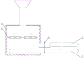
FIG. 1 is a schematic structural diagram of an embodiment of the present invention;
FIG. 2 is a schematic structural diagram of a fruit picking device and a seedling cutting device which are not shown in the embodiment of the present invention;
FIG. 3 is a schematic cross-sectional view of a fruit picking apparatus according to an embodiment of the present invention;
FIG. 4 is a schematic structural diagram of a fruit picking mechanism set according to an embodiment of the present invention;
FIG. 5 is a schematic structural diagram of two cutter sets of a fruit picking mechanism set according to an embodiment of the present invention when cutting segments are cut in cooperation;
FIG. 6 is a schematic structural diagram of two cutter sets of a fruit picking mechanism set with one structure in an embodiment of the present invention when the clamping section cooperates with the clamping;
FIG. 7 is a schematic structural diagram of two cutter sets of a fruit picking mechanism set with another structure according to another embodiment of the present invention when cutting segments are cut in cooperation;
FIG. 8 is a schematic structural diagram of two cutter sets of a fruit picking mechanism set of another structure in cooperation with a gripping section according to an embodiment of the present invention;
fig. 9 is a schematic structural view illustrating two props of a fruit picking mechanism set of another structure moving along a horizontal section after being separated according to another embodiment of the present invention;
FIG. 10 is a schematic view of a cutter set according to an embodiment of the present invention;
FIG. 11 is a schematic view of a cutter according to an embodiment of the present invention;
FIG. 12 is a schematic top view of a row of seedlings in an embodiment of the invention;
FIG. 13 is a schematic structural view of a rack for arranging seedlings according to an embodiment of the present invention;
FIG. 14 is a schematic view of a seedling arranging device according to an embodiment of the present invention;
FIG. 15 is a schematic structural view of another perspective of a seedling arranging device according to an embodiment of the present invention;
fig. 16 is a schematic structural diagram of a feeding mechanism of a seedling discharging device in an embodiment of the invention.
Reference numbers and corresponding part names in the drawings:
1-seedling arranging device, 11-shell, 12-seedling arranging teeth, 13-driving wheel, 14-second driving device, 15-protecting plate, 16-mounting frame, 17-top cover, 18-feeding mechanism, 181-feeding hopper, 182-vibrating motor, 183-sleeve, 184-third spring, 185-placing table, 19-seedling arranging area, 2-fruit picking device, 21-shell, 22-fruit picking mechanism group, 221-first guide rod, 222-second guide rod, 223-slide block, 224-first spring, 225-steering block, 226-push rod, 227-first driving device, 228-connecting rod, 229-cutter group, 230-mounting plate, 231-groove, 232-second spring, 233-cutter, 234-blade, 235-clamping groove, 23-screw, 24-collecting opening, 3-seedling cutting device, 4-lower conveying chain, 5-upper conveying chain, 6-rotary pressing piece and 61-blade.
Detailed Description
In order to make the objects, technical solutions and advantages of the present invention more apparent, the present invention is further described in detail below with reference to examples and accompanying drawings, and the exemplary embodiments and descriptions thereof are only used for explaining the present invention and are not meant to limit the present invention.
In the description of the present invention, it is to be understood that the terms "front", "rear", "left", "right", "upper", "lower", "vertical", "horizontal", "high", "low", "inner", "outer", etc. indicate orientations or positional relationships based on those shown in the drawings, and are only for convenience of description and simplicity of description, but do not indicate or imply that the device or element being referred to must have a particular orientation, be constructed in a particular orientation, and be operated, and therefore, should not be taken as limiting the scope of the invention.
Example 1:
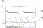
as shown in fig. 1 to 4, the ophiopogon japonicus cutting and fruit picking system comprises a lower conveying chain 4 and an upper conveying chain 5, a conveying area for clamping and conveying wheat seedlings is formed between the lower conveying chain 4 and the upper conveying chain 5, a fruit picking device 2 is arranged on one side of the conveying area, the fruit picking device 2 comprises at least one fruit picking mechanism group 22, the fruit picking mechanism group 22 comprises two fruit picking mechanisms which are arranged up and down, the fruit picking mechanisms comprise a control mechanism and a cutter group 229, the cutter group 229 of the two fruit picking mechanisms is used for moving along a rectangular movement track under the driving of the control mechanism, and sequentially passes through a cutting section and a clamping section of the rectangular movement track, in the cutting section, the two cutter groups 229 are matched with and cut the root tuber of the ophiopogon japonicus, and in the clamping section, the two cutter groups 229 are matched with and clamp the root tuber after cutting.
In this embodiment, the rectangular motion trajectory includes a cutting section, a clamping section, a vertical section, and a horizontal section that are connected in sequence. Wherein, cutting section and getting the section mutually perpendicular, and cutting section is located the outside of shell. A vertical section parallel to the cutting section and located inside the housing and a horizontal section parallel to the gripping section are used as the moving section.
During the removal, suppose that the initial position of cutter group is located vertical section bottom, two cutter groups move along vertical section dorsad, later get into the horizontal segment, and move to the ophiopogon root in carrying along the horizontal segment through the feed inlet, later get into the cutting section, two cutter groups move along the cutting section in opposite directions until when reaching the stroke limit, cut off the root of a tuber and be connected with the stem, or leave the incision on junction/root of a tuber, the root of a tuber is located the cutter group centre gripping of laminating mutually simultaneously, the matched cutter group is got the section along pressing and is removed and get into inside the shell afterwards, realize further separation at the removal in-process, after getting into the shell, cutter group gets into vertical section again and keeps away from each other, the root of a tuber portion of centre gripping then falls into the shell at this moment and collects.
In one or more embodiments, the length of the grasping section is greater than the length of the cutting section.
In some embodiments, the predetermined trajectory may be a circular, triangular, polygonal or irregular trajectory including a cutting section and a gripping section connected in series.
In some embodiments, the system further comprises a seedling cutting device 3, the seedling cutting device 3 is located at the opposite side of the fruit picking device 2, and the seedling cutting device 3 is used for performing a seedling cutting process on the radix ophiopogonis. In one embodiment, the seedling cutting device 3 can perform the seedling cutting process by using a leaf cutting blade in CN 112020989A. In one or more embodiments, the seedling cutting device 3 may adopt a structure the same as or similar to that of the fruit picking device 2 as the seedling cutting device, so as to separate the seedling tips of the ophiopogon japonicus from the main body in a separation mode combining cutting and clamping in the seedling cutting process.
In some embodiments, as shown in fig. 2, the two sides of the conveying mechanism are provided with rotary pressing members 6, and the rotary pressing members are used for pressing the height of the radix ophiopogonis piles on the lower conveying chain to be smaller than the height of the conveying area. The rotary pressing member is located between the conveying area and the housing. Before entering the conveying area, the rotating pressing piece in a rotating state utilizes the blades 61 to downwards press the two ends of the radix ophiopogonis, so that the overall height of the radix ophiopogonis piles is reduced to be lower than that of the conveying area, and the radix ophiopogonis piles can be enabled to completely and smoothly enter the conveying area. After entering the conveying area, the radix ophiopogonis piles are clamped by the conveying chains to move under the action of the extrusion force of the upper conveying chain and the lower conveying chain in the height recovery process.
In some embodiments, as shown in fig. 3, a screw 23 is disposed below the picking mechanism set 22, and the screw 23 is used for conveying the root of the block in the housing 21 to the outside of the housing 21 through a collecting port 24. In one or more embodiments, the bottom surface of the housing is sloped to maximize the height adjacent the collection port.
Compared with the separation mode of beating or cutting in the prior art, the separation mode of combining cutting and clamping is realized by using the control mechanism of the fruit picking mechanism group to drive the cutter group to move along the preset track and sequentially pass through the cutting section and the clamping section, the root of the tuber can be clamped and conveyed to the inside of the shell after cutting under the condition that the joint of the root of the tuber and the tuber of dwarf lilyturf is easy to cut, and the root of the tuber can be further separated by clamping and pulling after a cut is formed by cutting under the conditions that the joint of the root of the tuber and the tuber of dwarf lilyturf is high in toughness, a cutting point is positioned on the root of the tuber or other parts are difficult to cut, so that the fruit picking efficiency and the fruit picking rate of dwarf lilyturf are obviously improved; in addition, the upper cutter group and the lower cutter group are mutually supported in the matching process, the situation that the root of the block is unloaded by moving towards the opposite direction in the process of being flapped or cut by the rotary cutter can be effectively avoided, and the fruit picking effect is further improved.
Example 2:
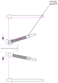
on the basis of embodiment 1, as shown in fig. 4 to 9, the control mechanism includes a first driving device 227 and a first guide rod 221, a sliding block 223 is slidably disposed on the first guide rod 221, a second guide rod 222 perpendicular to the first guide rod 221 is disposed on the sliding block 223, a connecting rod 228 is slidably disposed on the second guide rod 222, the connecting rod 228 is connected to a cutter set 229, a push rod 226 is hinged to the connecting rod 228, a steering block 225 is sleeved outside the push rod 226, the steering block 225 is connected to an output end of the first driving device 227, and a first spring 224 located between the steering block 225 and the connecting rod 228 is further sleeved outside the push rod 226.
In operation, as shown in fig. 4, the first driving device drives the turning block to rotate, the turning block changes the direction of the pushing rod, the connecting rod hinged with the push rod moves vertically upwards along the vertical section along the second guide rod under the driving of the push rod and reaches the upper limit of the stroke of the second guide rod, the steering block continues to rotate, the connecting rod positioned at the upper limit of the stroke of the second guide rod drives the second guide rod to move to the left stroke limit of the first guide rod along the horizontal section of the first guide rod, then the connecting rod enters the cutting section under the driving of the push rod and moves along the second guide rod, and at the lower limit of the stroke of the second guide rod, the cutter groups are matched with each other for cutting, the connecting rod positioned at the lower limit of the stroke of the second guide rod drives the second guide rod to move rightwards along the first guide rod until the right stroke limit of the first guide rod is reached, and the cutter groups complete the movement of the clamping section at the moment. And repeating the rectangular motion track of the cutter group under the driving of the first driving device to cut and clamp the root of the radix ophiopogonis block.
In one or more embodiments, the first drive device is a stepper motor or a servo motor.
In some embodiments, the turning block may be concentrically disposed, i.e., disposed at the center of the rectangular motion track, or may be eccentrically disposed, and the turning block 225 is disposed near the lower end of the second guide rod 222.
In some embodiments, as shown in fig. 5 and 6, the turning block is near the lower end of the second guide rod and the end of the first guide rod near the feed opening. In this embodiment, the turning block is close to an included angle between the cutting section and the clamping section of the rectangular motion track. During operation, get into the cutting section after, the vertical in-process that moves down of cutter group, first spring compress the energy storage earlier gradually and extend gradually after the energy release, when two cutter group contacts, can accelerate relative movement and then improve the effort of cutter group at the rhizome junction, reinforcing cutting effect. Subsequently, after entering the clamping section, the first spring gradually compresses the stored energy and then gradually extends the energy release, and in the energy release stage, the first spring pushes the connecting rod to rapidly move along the clamping section so as to apply gradually increased pulling force and enhance the separation effect. This eccentric structure can realize simultaneously that the spring of cutting section and clamp section releases the ability, utilizes the effort of first spring to exert gradual change's effort to rhizome junction or incision to be favorable to improving the cutting force at the cutting section, and be favorable to improving the pulling force at the section of pressing from both sides, improve the root tuber separation effect remarkably.
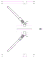
In some embodiments, as shown in fig. 7 to 9, the turning block is close to the lower end of the second guide rod and the end of the first guide rod away from the feed opening. To this eccentric rectangle movement track, during operation, get into the cutting section after, the vertical decurrent removal in-process of cutter unit, because turn to the piece far away apart from the cutting section, first spring is in natural state or extension state, and the influence that the cutter unit receives first spring is little, perhaps receives the release energy influence of certain degree, and two cutter units can be normal or accelerate the relative movement to improve the effort of cutter unit in the rhizome junction, reinforcing cutting effect.
Example 3:
on the basis of the above embodiment, as shown in fig. 10 and 11, the cutter set 229 includes a mounting plate 230, a plurality of grooves 231 are arranged on the mounting plate 230 side by side, a second spring 232 and a cutter 233 are slidably arranged in the grooves 231, and the second spring 232 connects the cutter 233 and the inner wall of the groove 231; the cutter 233 includes cutting edge 234 and centre gripping groove 235, and when upper and lower cutter 233 cooperates, two upper and lower centre gripping grooves 235 constitute the centre gripping region that is used for the grip block root, the centre gripping region is the toper structure, the internal diameter of toper structure is followed the direction that the one end that the centre gripping groove 235 is close to cutting edge 234 to the one end that the cutting edge 234 is kept away from to the centre gripping groove 235 and is increased gradually.
In this embodiment, the second spring not only can reset the cutter, and when pressing from both sides the root tuber portion of getting difficult to separate, the cutter at first keeps motionless, and when the mounting panel removed to vertical section along with the connecting rod, the second spring was elongated gradually and is held up power, and the root tuber portion received pulling force constantly increases, is greater than the threshold value immediately after with the tuber stem separation of dwarf lilyturf. And by combining the eccentric rectangular motion track, the second spring can quickly finish the force accumulation in the energy releasing process of the first spring, so that the instantaneous impulse force is generated to obviously improve the separation effect.
Example 4:
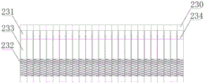
on the basis of the above embodiment, as shown in fig. 12 to 14, the seedling discharging device 1 is further included, the seedling discharging device 1 includes a casing 11 with an upward opening, a feeding port is formed on the casing 11, the lower conveying chain 4 extends into the casing 11 through the feeding port, at least two sets of seedling discharging mechanisms are arranged in the casing 11, a seedling discharging area 19 is formed between two adjacent sets of seedling discharging mechanisms, the seedling discharging area 19 is close to one side of the lower conveying chain 4, and the seedling discharging mechanisms are used for pushing down the radix ophiopogonis falling into the seedling discharging area 19, so that the root of the tuber and the tip of the radix ophiopogonis are respectively located at two sides of the conveying area; arrange seedling mechanism including being fixed in mounting bracket 16 on the casing 11 inner wall, be provided with second drive arrangement 14 on the mounting bracket 16, the output of second drive arrangement 14 is connected with drive wheel 13, the meshing has row seedling chain on drive wheel 13's the outer wall, be provided with a plurality of row seedling teeth 12 on the row seedling chain, row seedling tooth 12 is used for pushing down the tuber of dwarf lilyturf in row seedling region 19.
In one or more embodiments, the second drive is a stepper motor or a servo motor.
During feeding, the radix ophiopogonis is thrown into the shell from the top end of the shell. After the seedling planting machine enters the shell, the root tuber of the dwarf lilyturf tuber is heavier than the seedling tip part, so that the root tuber is positioned below and the seedling tip part is positioned above under the action of gravity, when the dwarf lilyturf tuber falls into a seedling discharging area between two adjacent groups of seedling discharging mechanisms, the root tuber further moves downwards and falls onto a lower conveying chain below the seedling discharging mechanisms, and the seedling tip part of the dwarf lilyturf tuber is positioned in the seedling discharging area. Then, the seedling discharging mechanism rotates in the same direction to push down the radix ophiopogonis, so that the radix ophiopogonis is orderly stacked on the lower conveying chain.
In one or more embodiments, the number of the driving wheels is two, and as shown in fig. 12, the two driving wheels are respectively close to two sides of the conveying chain, so that the seedling discharging chain has a length capable of covering the seedling discharging area, and the dwarf lilyturf tuber falling into the seedling discharging area can be pushed by the seedling discharging teeth.
In one or more embodiments, the upper end and the lower end of the seedling arranging chain are respectively provided with a protection plate 15, and the protection plates 15 can prevent radix ophiopogonis or other objects from falling into the seedling arranging chain or the driving wheel to influence the normal movement of the seedling arranging chain and the driving wheel.
In some embodiments, as shown in fig. 13, two adjacent seedling rows 12 on the same seedling row chain are connected by a hinge. Two adjacent seedling rows can relatively deflect at a certain angle to pass through the bent section of the driving wheel 13.
In some embodiments, the top surfaces of the conveying strips of the lower conveying chain are convex circular arc structures, and the circular arc structures are beneficial to guiding root tuber ends of the dwarf lilyturf tuber into gaps between two adjacent conveying strips. After the seedlings are pushed down by the seedling arranging mechanism, the root of the tuber of dwarf lilyturf positioned below the gap can be better positioned outside the conveying area.
The embodiment has utilized the characteristics that tuber root portion quality of dwarf lilyturf is greater than seedling point portion quality, make the whereabouts of dwarf lilyturf in the casing in-process can produce deflection of certain degree, seedling point portion is located row seedling region when falling to conveying mechanism on, and then promote the dwarf lilyturf seedling through row seedling mechanism in order to promote the dwarf lilyturf towards a direction, finally the dwarf lilyturf piles up on the conveying chain in an orderly manner, and the seedling point portion and/or the tuber root portion of dwarf lilyturf extend to the outside in conveying region, be convenient for follow-up carry out the tuber of dwarf lilyturf and cut seedling and/or pluck the fruit process in conveying process, the tuber of dwarf lilyturf feeding process has been simplified, realize automatic row of dwarf lilyturf, need not artifical further to adjust the position of dwarf lilyturf on conveying mechanism, the work load is reduced, and the production efficiency is improved.
Example 5:
on the basis of the above embodiment, as shown in fig. 16, a top cover 17 is installed on the top end of the housing 11, a feeding mechanism 18 is arranged on the top cover 17, the bottom end of the feeding mechanism 18 is located right above the seedling discharging area 19, the feeding mechanism 18 comprises a sleeve 183 installed on the top cover 17, a placing table 185 is arranged on the inner wall of the sleeve 183, a feeding hopper 181 is placed on the placing table 185, the top end of the feeding hopper 181 is located above the sleeve 183, a plurality of third springs 184 are arranged between the outer wall of the feeding hopper 181 and the inner wall of the sleeve 183, and a vibration motor 182 is arranged on the feeding hopper 181.
In this embodiment, after the feeder hopper that the tuber of dwarf lilyturf got into the vibration, the tuber of dwarf lilyturf that is located on the inclined section inner wall of feeder hopper was because the piece root is heavier and constantly adjust the direction in the feeder hopper, got into the sleeve after, the tuber of dwarf lilyturf through preliminary adjustment orientation continues to adjust the orientation at the in-process that falls down, finally, through the dual function of feeder hopper vibration section and sleeve extension section, the tuber of the overwhelming majority tuber of dwarf lilyturf homoenergetic all can be vertical down.
Example 6:
a dwarf lilyturf seedling cutting and fruit picking method adopts any one of the dwarf lilyturf seedling cutting and fruit picking systems, and comprises the following steps:
the radix ophiopogonis to be processed is conveyed to the conveying area through the lower conveying chain 4, and two ends of the radix ophiopogonis are respectively positioned at two sides of the conveying area;
the seedling cutting device 3 and the fruit picking device 2 respectively cut two ends of the radix ophiopogonis;
the upper and lower cutter groups 229 of the fruit picking mechanism group 22 of the fruit picking device 2 move along a rectangular motion track, and when the fruit picking mechanism group passes through a cutting section of the rectangular motion track, the two cutter groups 229 are matched with and cut the root tuber of the dwarf lilyturf tuber; thereafter, while passing through the grasping section of the rectangular movement locus, the two cutter groups 229 cooperate and grasp the cut root portion.
As used herein, "first," "second," "third," etc. (e.g., first spring, second spring, third spring, first guide bar, second guide bar, etc.) merely distinguish the respective components for clarity of description and are not intended to limit any order or to emphasize importance, etc. Further, the term "connected" used herein may be either directly connected or indirectly connected via other components without being particularly described.
The above-mentioned embodiments are intended to illustrate the objects, technical solutions and advantages of the present invention in further detail, and it should be understood that the above-mentioned embodiments are merely exemplary embodiments of the present invention, and are not intended to limit the scope of the present invention, and any modifications, equivalent substitutions, improvements and the like made within the spirit and principle of the present invention should be included in the scope of the present invention.
Claims (9)
1. A dwarf lilyturf seedling cutting and fruit picking system comprises a lower conveying chain (4) and an upper conveying chain (5), a conveying area for clamping and conveying wheat seedlings is formed between the lower conveying chain (4) and the upper conveying chain (5), a fruit picking device (2) is arranged on one side of the conveying area, it is characterized in that the fruit picking device (2) comprises at least one group of fruit picking mechanism group (22), the fruit picking mechanism group (22) comprises two fruit picking mechanisms which are arranged up and down, the fruit picking mechanisms comprise control mechanisms and cutter groups (229), the cutter groups (229) of the two fruit picking mechanisms are driven by the control mechanism to move along a rectangular motion track and sequentially pass through a cutting section and a clamping section of the rectangular motion track, in the cutting section, the two cutter groups (229) are matched with each other to cut the root tuber of the dwarf lilyturf, and in the clamping section, the two cutter groups (229) are matched with each other to clamp the cut root tuber; control mechanism includes first drive arrangement (227) and first guide bar (221), it is provided with slider (223) to slide on first guide bar (221), be provided with on slider (223) with first guide bar (221) second guide bar (222) of looks vertically, it is provided with connecting rod (228) to slide on second guide bar (222), connecting rod (228) are connected to cutter unit (229), and hinged joint has push rod (226) on connecting rod (228), the outside cover of push rod (226) is equipped with turns to piece (225), turn to piece (225) and be connected with the output of first drive arrangement (227), the outside of push rod (226) still overlaps and is equipped with and is located the first spring (224) between turning to piece (225) and connecting rod (228).
2. The radix ophiopogonis seedling cutting and fruit picking system according to claim 1, wherein the turning block (225) is eccentrically arranged in a rectangular motion track, and the turning block (225) is close to the lower end of the second guide rod (222).
3. The radix ophiopogonis seedling cutting and fruit picking system according to claim 1, wherein the cutter set (229) comprises a mounting plate (230), a plurality of grooves (231) are formed in the mounting plate (230) side by side, a second spring (232) and a cutter (233) are arranged in the grooves (231) in a sliding mode, and the second spring (232) is connected with the cutter (233) and the inner wall of the groove (231).
4. The radix ophiopogonis seedling cutting and fruit picking system according to claim 3, wherein the cutting knife (233) comprises a blade (234) and a clamping groove (235), when the upper and lower cutting knives (233) are matched, the upper and lower clamping grooves (235) form a clamping area for clamping the root of the block, the clamping area is of a conical structure, and the inner diameter of the conical structure gradually increases along the direction from one end of the clamping groove (235) close to the blade (234) to one end of the clamping groove (235) far away from the blade (234).
5. The radix ophiopogonis seedling cutting and fruit picking system according to claim 1, further comprising a seedling discharging device (1), wherein the seedling discharging device (1) comprises a shell (11) with an upward opening, a feeding port is formed in the shell (11), a lower conveying chain (4) extends into the shell (11) through the feeding port, at least two groups of seedling discharging mechanisms are arranged in the shell (11), a seedling discharging area (19) is formed between every two adjacent groups of seedling discharging mechanisms, the seedling discharging area (19) is close to one side of the lower conveying chain (4), and the seedling discharging mechanisms are used for pushing down radix ophiopogonis falling into the seedling discharging area (19), so that the root parts and the seedling tip parts of radix ophiopogonis are respectively located on two sides of the conveying area.
6. The radix ophiopogonis seedling cutting and fruit picking system according to claim 5, wherein the seedling discharging mechanism comprises a mounting frame (16) fixed on the inner wall of the shell (11), a second driving device (14) is arranged on the mounting frame (16), the output end of the second driving device (14) is connected with a driving wheel (13), a seedling discharging chain is meshed on the outer wall of the driving wheel (13), a plurality of seedling discharging teeth (12) are arranged on the seedling discharging chain, and the seedling discharging teeth (12) are used for pushing radix ophiopogonis in a seedling discharging area (19).
7. The radix ophiopogonis seedling cutting and fruit picking system according to claim 5, wherein a top cover (17) is installed on the top end of the shell (11), a feeding mechanism (18) is arranged on the top cover (17), the bottom end of the feeding mechanism (18) is located right above the seedling discharging area (19), the feeding mechanism (18) comprises a sleeve (183) installed on the top cover (17), a placing table (185) is arranged on the inner wall of the sleeve (183), a feeding hopper (181) is placed on the placing table (185), the top end of the feeding hopper (181) is located above the sleeve (183), a plurality of third springs (184) are arranged between the outer wall of the feeding hopper (181) and the inner wall of the sleeve (183), and a vibration motor (182) is arranged on the feeding hopper (181).
8. The radix ophiopogonis seedling cutting and fruit picking system according to any one of claims 1-7, further comprising a seedling cutting device (3), wherein the seedling cutting device (3) is located on the opposite side of the fruit picking device (2), and the seedling cutting device (3) is used for performing a seedling cutting process on radix ophiopogonis.
9. The seedling cutting and fruit picking method for the radix ophiopogonis is, which is characterized by adopting the seedling cutting and fruit picking system for the radix ophiopogonis as claimed in claim 8, and comprises the following steps:
the radix ophiopogonis to be processed is conveyed to the conveying area through a lower conveying chain (4), and two ends of the radix ophiopogonis are respectively positioned at two sides of the conveying area;
the seedling cutting device (3) and the fruit picking device (2) respectively cut two ends of the radix ophiopogonis;
the upper and lower cutter groups (229) of a fruit picking mechanism group (22) of the fruit picking device (2) move along a rectangular motion track, and when the fruit picking mechanism group passes through a cutting section of the rectangular motion track, the two cutter groups (229) are matched with each other and cut the root tuber of the dwarf lilyturf tuber; then, when passing through a grasping section of a rectangular movement locus, the two cutter groups (229) cooperate and grasp the cut root portion.
Priority Applications (1)
| Application Number | Priority Date | Filing Date | Title |
|---|---|---|---|
| CN202110273670.0A CN113016337B (en) | 2021-03-15 | 2021-03-15 | Radix ophiopogonis seedling cutting and fruit picking system and method |
Applications Claiming Priority (1)
| Application Number | Priority Date | Filing Date | Title |
|---|---|---|---|
| CN202110273670.0A CN113016337B (en) | 2021-03-15 | 2021-03-15 | Radix ophiopogonis seedling cutting and fruit picking system and method |
Publications (2)
| Publication Number | Publication Date |
|---|---|
| CN113016337A CN113016337A (en) | 2021-06-25 |
| CN113016337B true CN113016337B (en) | 2022-02-08 |
Family
ID=76468697
Family Applications (1)
| Application Number | Title | Priority Date | Filing Date |
|---|---|---|---|
| CN202110273670.0A Active CN113016337B (en) | 2021-03-15 | 2021-03-15 | Radix ophiopogonis seedling cutting and fruit picking system and method |
Country Status (1)
| Country | Link |
|---|---|
| CN (1) | CN113016337B (en) |
Families Citing this family (1)
| Publication number | Priority date | Publication date | Assignee | Title |
|---|---|---|---|---|
| CN117099980B (en) * | 2023-10-25 | 2023-12-22 | 四川省畜牧科学研究院 | Mixed feed processing equipment and method based on elephant grass |
Citations (7)
| Publication number | Priority date | Publication date | Assignee | Title |
|---|---|---|---|---|
| SU1097230A1 (en) * | 1983-03-28 | 1984-06-15 | Чувашский сельскохозяйственный институт | Working member of cabbage-harvesting machine |
| US5161356A (en) * | 1990-09-07 | 1992-11-10 | Norbert Pick | Stalk chopper and crusher accessory |
| CN105325114A (en) * | 2015-11-21 | 2016-02-17 | 泉州市永茂电子科技有限公司 | Drawing device of whole plant drawing machine for cotton stalks |
| CN109937693A (en) * | 2019-03-27 | 2019-06-28 | 吴文松 | A kind of automatic seed harvester of pineapple |
| CN110073793A (en) * | 2019-05-28 | 2019-08-02 | 中国农业大学 | A kind of Radix Ophiopogonis combined harvester |
| CN210496664U (en) * | 2019-09-06 | 2020-05-12 | 安国圣山药业有限公司 | Traditional chinese medicine processing is with comminution device |
| CN112020989A (en) * | 2020-08-05 | 2020-12-04 | 四川老李科技有限公司 | Machine for picking fruits and cutting seedlings of radix ophiopogonis |
-
2021
- 2021-03-15 CN CN202110273670.0A patent/CN113016337B/en active Active
Patent Citations (7)
| Publication number | Priority date | Publication date | Assignee | Title |
|---|---|---|---|---|
| SU1097230A1 (en) * | 1983-03-28 | 1984-06-15 | Чувашский сельскохозяйственный институт | Working member of cabbage-harvesting machine |
| US5161356A (en) * | 1990-09-07 | 1992-11-10 | Norbert Pick | Stalk chopper and crusher accessory |
| CN105325114A (en) * | 2015-11-21 | 2016-02-17 | 泉州市永茂电子科技有限公司 | Drawing device of whole plant drawing machine for cotton stalks |
| CN109937693A (en) * | 2019-03-27 | 2019-06-28 | 吴文松 | A kind of automatic seed harvester of pineapple |
| CN110073793A (en) * | 2019-05-28 | 2019-08-02 | 中国农业大学 | A kind of Radix Ophiopogonis combined harvester |
| CN210496664U (en) * | 2019-09-06 | 2020-05-12 | 安国圣山药业有限公司 | Traditional chinese medicine processing is with comminution device |
| CN112020989A (en) * | 2020-08-05 | 2020-12-04 | 四川老李科技有限公司 | Machine for picking fruits and cutting seedlings of radix ophiopogonis |
Non-Patent Citations (1)
| Title |
|---|
| 《4WM-100B型麦冬收获机在三台县的研究及应用情况》;王义鹏;《四川农业科技》;20200815;72-76 * |
Also Published As
| Publication number | Publication date |
|---|---|
| CN113016337A (en) | 2021-06-25 |
Similar Documents
| Publication | Publication Date | Title |
|---|---|---|
| CN112166808B (en) | Harvesting device and method for pipeline-cultivated leaf vegetables | |
| CN107826611B (en) | A kind of sawdust recycling equipment | |
| CN113016337B (en) | Radix ophiopogonis seedling cutting and fruit picking system and method | |
| CN107360779B (en) | Profiling seedling cutting and flexible speed reducing conveying device of garlic harvester | |
| CN216134844U (en) | Automatic pineapple picking machine | |
| CN1939162A (en) | White-gourd peeler | |
| CN108201157B (en) | Sweetleaf chrysanthemum disleaving wind selector | |
| CN109729824A (en) | Corn ear device for peeling and method | |
| CN108450126B (en) | Automatic stevia rebaudiana harvesting and defoliating integrated machine | |
| CN102273364B (en) | Small semi-automatic stevia rebaudiana leaf picking machine | |
| CN208509631U (en) | A kind of picker for fruits and vegetables | |
| CN108244678B (en) | Automatic change sweetleaf chrysanthemum device that goes out leaf | |
| CN209268024U (en) | A kind of onion, garlic class crop cut stem device | |
| CN108848894B (en) | Lettuce harvesting device | |
| CN214592940U (en) | Radix ophiopogonis fruit picking device | |
| CN108340416B (en) | Automatic stevia rebaudiana grading device | |
| CN215031149U (en) | Leaf cleaning equipment after winter jujube is collected to agricultural | |
| CN103733807B (en) | Hot pickled mustard tube grain header | |
| CN113524292B (en) | Adjustable equipment of cutting dish of practical function type | |
| CN113057348B (en) | Intelligent manufacturing equipment and method of canned fruits | |
| CN202222164U (en) | Small semi-automatic stevia rebaudiana leaf picker | |
| CN214482281U (en) | Arrange seedling device and tuber of dwarf lilyturf cut seedling and pluck fruit system | |
| CN110249787A (en) | A kind of ecological agriculture vegetable cultivation harvesting apparatus | |
| SU1687086A1 (en) | Tea-leaf harvesing apparatus operating tool | |
| CN208079855U (en) | A kind of cherry picking tool |
Legal Events
| Date | Code | Title | Description |
|---|---|---|---|
| PB01 | Publication | ||
| PB01 | Publication | ||
| SE01 | Entry into force of request for substantive examination | ||
| SE01 | Entry into force of request for substantive examination | ||
| GR01 | Patent grant | ||
| GR01 | Patent grant |