CN112974179A - Nitrile butadiene rubber cement sizing process of low-temperature-resistant nitrile butadiene protective gloves - Google Patents
Nitrile butadiene rubber cement sizing process of low-temperature-resistant nitrile butadiene protective gloves Download PDFInfo
- Publication number
- CN112974179A CN112974179A CN202110194668.4A CN202110194668A CN112974179A CN 112974179 A CN112974179 A CN 112974179A CN 202110194668 A CN202110194668 A CN 202110194668A CN 112974179 A CN112974179 A CN 112974179A
- Authority
- CN
- China
- Prior art keywords
- colloid
- glue
- gluing
- temperature
- nitrile
- Prior art date
- Legal status (The legal status is an assumption and is not a legal conclusion. Google has not performed a legal analysis and makes no representation as to the accuracy of the status listed.)
- Withdrawn
Links
Images


Classifications
-
- B—PERFORMING OPERATIONS; TRANSPORTING
- B05—SPRAYING OR ATOMISING IN GENERAL; APPLYING FLUENT MATERIALS TO SURFACES, IN GENERAL
- B05D—PROCESSES FOR APPLYING FLUENT MATERIALS TO SURFACES, IN GENERAL
- B05D1/00—Processes for applying liquids or other fluent materials
- B05D1/18—Processes for applying liquids or other fluent materials performed by dipping
-
- B—PERFORMING OPERATIONS; TRANSPORTING
- B05—SPRAYING OR ATOMISING IN GENERAL; APPLYING FLUENT MATERIALS TO SURFACES, IN GENERAL
- B05B—SPRAYING APPARATUS; ATOMISING APPARATUS; NOZZLES
- B05B15/00—Details of spraying plant or spraying apparatus not otherwise provided for; Accessories
- B05B15/50—Arrangements for cleaning; Arrangements for preventing deposits, drying-out or blockage; Arrangements for detecting improper discharge caused by the presence of foreign matter
-
- B—PERFORMING OPERATIONS; TRANSPORTING
- B05—SPRAYING OR ATOMISING IN GENERAL; APPLYING FLUENT MATERIALS TO SURFACES, IN GENERAL
- B05C—APPARATUS FOR APPLYING FLUENT MATERIALS TO SURFACES, IN GENERAL
- B05C11/00—Component parts, details or accessories not specifically provided for in groups B05C1/00 - B05C9/00
- B05C11/10—Storage, supply or control of liquid or other fluent material; Recovery of excess liquid or other fluent material
-
- B—PERFORMING OPERATIONS; TRANSPORTING
- B05—SPRAYING OR ATOMISING IN GENERAL; APPLYING FLUENT MATERIALS TO SURFACES, IN GENERAL
- B05C—APPARATUS FOR APPLYING FLUENT MATERIALS TO SURFACES, IN GENERAL
- B05C3/00—Apparatus in which the work is brought into contact with a bulk quantity of liquid or other fluent material
- B05C3/02—Apparatus in which the work is brought into contact with a bulk quantity of liquid or other fluent material the work being immersed in the liquid or other fluent material
- B05C3/09—Apparatus in which the work is brought into contact with a bulk quantity of liquid or other fluent material the work being immersed in the liquid or other fluent material for treating separate articles
- B05C3/10—Apparatus in which the work is brought into contact with a bulk quantity of liquid or other fluent material the work being immersed in the liquid or other fluent material for treating separate articles the articles being moved through the liquid or other fluent material
-
- B—PERFORMING OPERATIONS; TRANSPORTING
- B05—SPRAYING OR ATOMISING IN GENERAL; APPLYING FLUENT MATERIALS TO SURFACES, IN GENERAL
- B05C—APPARATUS FOR APPLYING FLUENT MATERIALS TO SURFACES, IN GENERAL
- B05C9/00—Apparatus or plant for applying liquid or other fluent material to surfaces by means not covered by any preceding group, or in which the means of applying the liquid or other fluent material is not important
- B05C9/08—Apparatus or plant for applying liquid or other fluent material to surfaces by means not covered by any preceding group, or in which the means of applying the liquid or other fluent material is not important for applying liquid or other fluent material and performing an auxiliary operation
- B05C9/14—Apparatus or plant for applying liquid or other fluent material to surfaces by means not covered by any preceding group, or in which the means of applying the liquid or other fluent material is not important for applying liquid or other fluent material and performing an auxiliary operation the auxiliary operation involving heating or cooling
Abstract
The invention relates to a butyronitrile rubber cement gluing process of a low-temperature-resistant butyronitrile protective glove, which comprises the following steps: step one, a first glue injection process; step two, a hand mask cooling process; step three, pre-gluing the hand membrane; step four, completely gluing the hand membrane, and driving the glove module to move downwards along the horizontal part of the second horizontal part d to the groove body of the dipping groove by the guide rail to finish gluing; step five, cleaning a tank body of the impregnation tank; sixthly, impurity discharging; step seven, completing the colloid cooling circulation process after gluing; step eight, a new colloid supplementing procedure; step nine, a bubble removing process, wherein the colloid at the bottom is centrifugally thrown out to the upper surface of the glue dipping groove body under the guidance of the wide-mouth shed, and bubbles on the upper surface of the glue dipping groove body are punctured; the invention solves the technical problem that the gloves are not glued uniformly because the flowing colloid is in a flowing state and the impact force is different when the flowing colloid is attached to the hand membrane in the gluing process.
Description
Technical Field
The invention relates to the technical field of gloves, in particular to a butyronitrile rubber cement gluing process of a low-temperature-resistant butyronitrile protective glove.
Background
At present, commonly used working gloves or labor protection gloves are all directly woven by cotton, polyester cotton yarn, nylon and other materials, the gloves do not have acid/alkali resistance when in use, are not anti-skidding, are easy to wear and tear, are frequently replaced, increase the cost, and lack a butyronitrile rubber bead dispensing device for preventing the gloves from skidding.
Patent document CN2017206938787 discloses a production device for nitrile rubber antiskid gloves, which comprises a fixed frame, the side surface of the fixed frame is provided with a supporting leg, the upper end of the fixed frame is provided with a conveying device, the upper end of the rear side surface of the fixed frame is fixed with a mounting seat, the sliding plate which is connected with the sliding groove in a sliding way is arranged in the sliding groove of the mounting seat, the production device of the butyronitrile rubber antiskid gloves has simple principle and convenient implementation, the butyronitrile rubber is used as the bead material of the anti-skid glove, the stability is strong, the generated anti-skid particles are uniform, wear-resistant and acid and alkali resistant, simultaneously the environmental protection, the extrusion of pressing the flitch in the pressure feed box makes the butyronitrile glue extrude from the discharge opening and adheres to on gloves, extrudees evenly, is equipped with storage case and delivery pump and realizes the self-feeding of butyronitrile glue, and the articulated lagging of hand type makes things convenient for the installation and the location of gloves, realizes anti-skidding glove's streamlined production with the conveyer cooperation.
However, in the actual application process, the inventor finds that the glue is in a flowing state during the gluing process, so that the flowing glue is attached to the hand membrane under different impact forces, thereby causing the problem of uneven gluing of the gloves.
Disclosure of Invention
Aiming at the defects of the prior art, the invention aims to provide the technical problems that when the glove is matched with flowing colloid in the transmission process, the pre-gluing operation is carried out before the formal gluing operation, and the pre-gluing operation is carried out on the glove module in the transmission process of the colloid with higher temperature after gluing, so that the temperature difference between the glove module and the colloid is too large, and the quality of the colloid can be influenced in the formal and complete gluing operation, thereby solving the technical problem that the glove gluing is not uniform due to different impact forces when the flowing colloid is attached to the hand film because the colloid is in a flowing state in the gluing process.
Aiming at the technical problems, the technical scheme is as follows: a nitrile butadiene rubber cement gluing process of a low temperature resistant nitrile butadiene protective glove comprises the following steps:
firstly, in a first glue injection process, an outlet valve of a material storage box body is enlarged, glue in the material storage box body is output into a driving shaft a from a connecting pipe a through a pump body, and flows into a glue dipping tank body until the glue dipping tank body is filled with glue;
step two, a hand membrane cooling process, wherein the glove modules are driven to downwards transmit along the inclined planes of the first inclined part a, the second inclined part c and the third inclined part e in parallel by a guide rail, the driving shaft b is synchronously transmitted with the driving shaft a through a synchronous belt, the driving shaft b drives the turbine b to synchronously transmit, the upward flow colloid pumping is completed to provide power, and meanwhile, the rotating radiating blades on the glove modules complete the hand membrane cooling work in the transmission process;
step three, a hand membrane pre-gluing process, wherein glue in the gluing space flows from bottom to top, the temperature of the glue of the second horizontal part d is increased after the glue is glued and flows into the first horizontal part b, and the guide rail drives the glove module to move downwards along the first horizontal part b to a glue dipping groove body to complete pre-gluing work;
step four, completely gluing the hand membrane, and driving the glove module to move downwards along the horizontal part of the second horizontal part d to the groove body of the dipping groove by the guide rail to finish gluing;
step five, cleaning the tank body of the impregnation tank, wherein the chain mechanism drives the cleaning mechanism, so that the cleaning mechanism finishes the automatic cleaning work on the bottom of the tank body of the impregnation tank in the process that the colloid flows along the tank body of the impregnation tank for a circle;
step six, impurity discharging, wherein when the brush roll moves to the first discharging assembly, the chain moving mechanism stops working at the moment, the distance sensor drives the horizontal pushing cylinder to automatically start, the limiting plate moves to the bottom of the groove body of the gum dipping groove, impurities are blocked by the limiting plate, colloid is output through the filter screen part of the limiting plate, then the telescopic unit a continues to extrude, the telescopic unit a acts on the telescopic unit a through the translation piece, the pushing cylinder discharges sediments in front of the brush roll, after the pushing cylinder enters the protruding platform, the control door is automatically opened, the colloid and the impurities enter the first collecting box together, glue under the filter plate is collected, and impurities on the filter plate are collected;
step seven, completing the colloid cooling circulation process after gluing, enabling the colloid discharged from the first collecting box to enter the material storage box body through the connecting pipe b, and completing the colloid cooling work in the connecting pipe b by the cooling medium in the transmission process;
step eight, a new colloid supplementing process, namely outputting the colloid in the storage box body into a driving shaft a from a connecting pipe a through a pump body, centrifugally throwing the colloid at the bottom of the driving shaft a into a glue dipping groove body under the guidance of a wide-mouth shed in the circumferential process of the driving shaft a, mixing the colloid with the colloid in the glue dipping groove body, and finally reusing the colloid with the temperature reaching the standard to an upper glue space as a stock solution for gluing;
and step nine, a bubble removing process, which is synchronous with the step eight, wherein the colloid at the bottom is centrifugally thrown out to the upper surface of the glue dipping tank body under the guidance of the wide-mouth shed, and bubbles on the upper surface of the glue dipping tank body are punctured.
Preferably, the latex temperature detection mode in the dipping tank body adopts a temperature sensor.
Preferably, in the first step, the temperature of the latex in the dip tank body is 20-28 ℃.
Preferably, the temperature of the latex in the first horizontal section is 26 to 28 ℃.
Preferably, the temperature of the latex in the stock tank is 18-20 ℃.
Preferably, the temperature of the latex in the third inclined part is 22 to 24 ℃.
Preferably, the temperature of the glove module before entering the dipping tank body 2 is 80-85 ℃.
Preferably, the temperature of the glove module after entry into second horizontal portion 20b is 60-75 ℃.
Preferably, in the second step, the rotation speed of the turbine b is 89 rpm.
The invention has the beneficial effects that:
(1) according to the invention, through setting the hand membrane cooling process, the hand membrane pre-gluing process and the hand membrane complete gluing process, when the gloves are matched with flowing glue in the transmission process, the pre-gluing process is firstly carried out before the formal gluing process, and the glove module is firstly pre-glued in the higher-temperature glue transmission process after gluing, so that the phenomenon that the temperature difference between the glove module and the glue temperature is too large, the quality of the glue is influenced in the formal and complete gluing process is avoided, and the gluing effect is improved;
(2) according to the invention, the colloid in the glue dipping tank is set to be in a flowing state, so that the glued colloid is circularly output, the transmission mechanism is matched with the first impurity collecting mechanism, a part of the colloid which is simultaneously taken out in the impurity removing process and is glued is discharged, cooling work is carried out after the colloid is discharged, the colloid is recycled, and after a part of the glued colloid is discharged, new colloid enters the glue dipping tank at a lower temperature, so that the temperature to be glued reaches the standard temperature, and the gluing effect is further improved;
(3) according to the automatic glue-dipping tank body cleaning device, the cleaning mechanism is driven by the chain mechanism, so that the cleaning mechanism finishes automatic cleaning work on the side wall and the bottom of the glue-dipping tank body in the process that glue flows for one circle along the glue-dipping tank body 2, the glue-dipping tank body is guaranteed to be kept in a clean state all the time in the gluing work process, on the other hand, the traditional machine halt is replaced to discharge the glue, the automatic cleaning work on the glue-dipping tank body is manually carried out, the timeliness is high, extra labor force output is replaced, and the production cost is reduced;
(4) according to the invention, by arranging the first impurity collecting mechanism and the second impurity collecting mechanism, after the cleaning mechanism finishes a circle of cleaning work on the groove body of the gum dipping groove, the first impurity collecting mechanism automatically discharges and collects precipitated colloid, then the first impurity collecting mechanism 5 is utilized to carry out slag removal work, the second impurity collecting mechanism drives the cleaning mechanism to carry out slag removal work on the cleaning surface, and meanwhile, the cleaning surface is switched to be a new cleaning surface, so that the cleaning effect is improved, and the service life of the cleaning surface is prolonged.
In conclusion, the device has the advantages of simple structure and uniform gluing, and is particularly suitable for the technical field of gloves.
Drawings
In order to more clearly illustrate the technical solutions of the embodiments of the present invention, the drawings needed to be used in the description of the embodiments are briefly introduced below, and it is obvious that the drawings described below are only some embodiments of the present invention, and it is obvious for those skilled in the art that other drawings can be obtained according to the drawings without creative efforts.
FIG. 1 is a schematic flow diagram of a nitrile butadiene rubber cement sizing process of a low temperature resistant nitrile butadiene protective glove.
Fig. 2 is a schematic structural diagram of a butyronitrile ultrathin antiskid labor protection glove manufacturing device.
FIG. 3 is a schematic structural diagram of the body of the dip tank.
FIG. 4 is a schematic front view of the body of the dip tank.
Fig. 5 is a first structural diagram of the guide assembly.
Fig. 6 is a schematic structural diagram of a guide assembly.
Fig. 7 is a schematic diagram of the transmission operation of the guide assembly.
FIG. 8 is a schematic view of the bubble removal assembly.
Fig. 9 is a schematic structural diagram of the second transmission assembly.
Fig. 10 is a first structural schematic diagram of the cleaning mechanism.
Fig. 11 is a second schematic structural diagram of the cleaning mechanism.
Fig. 12 is a third schematic structural view of the cleaning mechanism.
Fig. 13 is a fourth schematic structural view of the cleaning mechanism.
Fig. 14 is a schematic structural diagram of the cleaning mechanism.
Fig. 15 is a sixth schematic structural view of the cleaning mechanism.
Fig. 16 is a first schematic structural diagram of the second impurity collecting mechanism.
Fig. 17 is a second schematic structural view of the second impurity collecting mechanism.
Fig. 18 is a first schematic structural diagram of the first impurity collecting mechanism.
Fig. 19 is a second schematic structural view of the first impurity collecting mechanism.
Fig. 20 is a third schematic structural view of the first impurity collecting mechanism.
Fig. 21 is a fourth schematic structural view of the first impurity collecting mechanism.
Fig. 22 is a schematic structural view five of the first impurity collecting mechanism.
Fig. 23 is a schematic structural view of the swivel assembly.
Fig. 24 is a schematic structural view of the cooling assembly.
Fig. 25 is a schematic structural diagram of the first transmission assembly.
Detailed Description
The technical scheme in the embodiment of the invention is clearly and completely explained by combining the attached drawings.
Example one
As shown in figure 1, the butyronitrile rubber cement sizing process of the low-temperature-resistant butyronitrile protective glove comprises the following steps:
step one, in a first glue injection process, firstly, an outlet valve of a material storage box 231 is enlarged, glue in the material storage box 231 is output into a driving shaft a212 from a connecting pipe a232 through a pump body, and flows into a glue dipping groove body 2 until the glue dipping groove body 2 is filled with glue;
step two, a hand membrane cooling process, in which the guide track 131 drives the glove module 12 to downwards transmit along the inclined planes of the first inclined part 20a, the second inclined part 20c and the third inclined part 20e in parallel, the driving shaft b322 is synchronously transmitted with the driving shaft a22 through a synchronous belt, the driving shaft b322 drives the turbine b to synchronously transmit, so that the power supply effect on the upward flowing colloid pumping is completed, and meanwhile, the heat dissipation blades 323 rotating on the driving shaft b complete the hand membrane cooling work in the transmission process;
step three, a pre-gluing process of the hand membrane, wherein glue in the gluing space 202 flows from bottom to top, the glue in the second horizontal part 20d flows into the first horizontal part 20b after gluing, and the guide rail 131 drives the glove module 12 to move downwards along the first horizontal part 20b to the inside of the glue dipping groove body 2 to complete pre-gluing work;
step four, the hand membrane is completely glued, and the guide rail 131 drives the glove module 12 to move downwards along the horizontal part of the second horizontal part 20d to the dip tank body 2 to finish gluing;
step five, in the step of cleaning the body of the impregnation tank, the chain mechanism 205 drives the cleaning mechanism 4, so that the cleaning mechanism 4 finishes the automatic cleaning work on the bottom of the body 2 of the impregnation tank in the process that the colloid flows along the body 2 of the impregnation tank for a circle;
step six, impurity discharging, wherein when the brush roll 48 moves to the first discharging assembly 51, the chain moving mechanism 205 stops working, the distance sensor drives the horizontal pushing cylinder 511 to automatically start, the limiting plate 513 moves to the bottom of the glue dipping groove body 2, impurities are blocked by the limiting plate 513, colloid is output through a filter screen part of the limiting plate 513, then the telescopic unit a512 continues to extrude, the telescopic unit a512 acts on the telescopic unit a512 through the translation piece 517, the pushing cylinder 514 discharges sediments in front of the brush roll 48, after the pushing cylinder 514 enters the protruding platform 521, the control door 522 is automatically opened, the colloid and the impurities enter the first collecting box 523 together, the glue under the filter plate 524 is collected, and the impurities on the filter plate 524 are collected;
step seven, the colloid cooling circulation process after gluing is completed, the colloid discharged from the first collecting box 523 enters the storage box 231 through the connecting pipe b233, and the cooling medium 234 completes the cooling work of the colloid in the connecting pipe b233 in the transmission process;
step eight, a new colloid supplementing process, namely outputting the colloid in the storage box 231 into the driving shaft a212 from the connecting pipe a232 through the pump body, centrifugally throwing the colloid at the bottom of the driving shaft a212 into the dipping groove body 2 under the guidance of the wide-mouth shed 221 in the circumferential process of the driving shaft a212, mixing the colloid with the colloid in the dipping groove body 2, and finally reusing the colloid with the temperature reaching the standard to the upper glue space 202 as a stock solution for gluing work;
and step nine, a bubble removing process, which is synchronous with the step eight, wherein the colloid at the bottom is centrifugally thrown out to the upper surface of the glue dipping tank body 2 under the guidance of the wide-mouth shed 221, and bubbles on the upper surface of the glue dipping tank body 2 are punctured.
Further, a temperature sensor is adopted in a latex temperature detection mode in the dip tank body 2.
Further, in the first step, the temperature of the latex in the dip tank body 2 is 20-28 ℃.
Further, the temperature of the latex in the stock tank 231 is 18 to 20 ℃.
Further, the latex temperature in the third inclined portion 20e is 22 to 24 ℃.
Further, the temperature of the glove module 12 before entering the dipping tank body 2 is 80-85 ℃.
Further, the temperature of glove module 12 after entry into first horizontal portion 20b is 75-80 ℃.
Further, the temperature of glove module 12 after entry into second horizontal portion 20b is 60-75 ℃.
Further, the temperature of glove module 12 after entry into second horizontal portion 20b is 60-75 ℃.
Further, in the second step, the rotation speed of the turbine b is 89 rpm.
Example two
As shown in figure 2, a butyronitrile ultra-thin anti-skidding labor protection glove manufacturing device comprises:
the glove conveying mechanism 1 comprises a conveying unit 11, a plurality of groups of glove modules 12 uniformly arranged on the conveying unit 11 at equal intervals and a guide component 13 for driving the glove modules 12 to lift;
the glue dipping tank body 2 is obliquely and downwards arranged and is positioned below the transmission unit 11, the glue dipping tank body 2 is of an oval structure, a partition plate 201 is arranged along the middle of the glue dipping tank body 2 and along the length direction of the glue dipping tank body 2, a glue applying space 202 and an impurity discharging space 203 are formed between the glue dipping tank body 2 and the partition plate 201, and the glue dipping tank body 2 is smoothly and transitionally connected by a first inclined part 20a, a first horizontal part 20b, a second inclined part 20c, a second horizontal part 20d and a third inclined part 20e along the oblique and downwards direction;
the transmission mechanism 204 comprises a first transmission assembly 31 arranged at the third inclined part 20e and positioned in the impurity discharging space 203, a second transmission assembly 32 arranged at the lower end of the first inclined part 20a and positioned in the impurity gluing space 202, the first transmission assembly 31 and the second transmission assembly 32 are in synchronous transmission, the first transmission assembly 31 comprises a rotary assembly 21 arranged at the lower end part of the dip tank body 2 and positioned in the impurity discharging space 203, a bubble removing assembly 22 arranged on the rotary assembly 21 and used for spraying liquid into the dip tank body 2, and a cooling assembly 23 with one end communicated with the bubble removing assembly 22;
the chain-driven mechanism 205 is arranged right above the partition plate 201 and synchronously carries out conveying work along the transmission direction of water in the dip tank body 2, and the chain-driven mechanism 205 is intermittently started;
the cleaning mechanism 4 is arranged along the transmission direction of the chain mechanism 205, and the cleaning mechanism 4 is used for cleaning the bottom of the impregnation tank body 2;
the first impurity collecting mechanism 5 comprises a first discharging assembly 51 arranged in the partition plate 201 and a first collecting assembly 52 which is communicated with the cooling assembly 23 and used for collecting impurities discharged by the first discharging assembly 51; and
and the second impurity collecting mechanism 6 is arranged above the dip tank body 2, and comprises a switching component 61 for driving the cleaning mechanism 4 to automatically switch the decontamination surface and a second collecting component 62 for cleaning the cleaning mechanism 4 in the switching process for the second time.
It should be noted that if the nitrile latex is left to stand for exhausting after the completion of the compounding, the used mold is unglazed, if the mold film using the glazed mold is excessively shrunk, the temperature of the mold does not exceed 70 ℃ after the coagulant is dried, because the temperature is exceeded, the film is not formed well, the film starts to gel after the dipping of the eight-size, and the pH value of the right compounding ensures that the process is completed before the leaching stage. Leaching the gloves, wherein the sirloin latex is stable, a large amount of surfactant is present in the wet gel, and the leaching water removes the excessive surfactant and residues of calcium chloride and soluble impurities, wherein the leaching temperature does not exceed 45 ℃; above this temperature the film will shrink. The final stage of the process is vulcanization, the vulcanization temperature is high because the nitrile latex has no pre-vulcanization, the oven temperature must exceed 110 ℃ in the vulcanization cycle, the optimal vulcanization condition is that 8-9 ℃ is started, then the temperature is increased to 110-120 ℃, finally 80-9 ℃ is started, the nitrile gloves which are not vulcanized sufficiently will generate wrinkles, stickiness and damage durability, and after demoulding, the semi-finished gloves are required to be chloridized to remove surface stickiness, so the temperature of the hand mould cannot be too high, the temperature of the rubber material is below 24 ℃, and the pinhole phenomenon of the finished products can be reduced to the maximum extent.
In the embodiment, the glue dipping tank body 2 is obliquely and upwards arranged and is arranged in a single-layer structure, on one hand, the single-layer opening upwards arranged replaces the traditional upper and lower rail type connection, so that the glue dipping tank is not required to be disassembled for cleaning, is simple and rapid, and can ensure that the glue always keeps a flowing state in the inclination process on the glue dipping tank body 2, the glue is not easy to precipitate, the uniform degree of gluing is facilitated, and the product quality is improved; on the other hand, the processing is convenient, and the production cost is reduced.
It should be noted that, if the dipping tank body 2 adopts a flat-layer inclined upward structure, the force of the flowing fluid acting on the glove modules 12 in continuous transmission is different due to the fact that the gravity does work at the changed edge, and the gluing force of the entering products is not uniform, in order to solve the technical problem, the inventor changes the flat structure of the dipping tank body 2 into a multi-section structure, the second horizontal part 20d is a horizontal structure, the adhesive force between the glove modules 12 and the glue conveyed in the state is constant, and further, the gluing force of the glove modules 12 is uniform, so that the effect of uniform gluing is improved.
Further, as shown in fig. 6, the glove module 12 includes:
a base b121, the base b121 being disposed on any one of the links of the transfer unit 11;
the telescopic unit c122 is fixedly arranged on the base b121 and is vertically arranged downwards; and
and a hand film 123, wherein the hand film 123 is rotatably arranged at the lower end of the telescopic unit c 122.
Further, as shown in fig. 7 to 6, the guide assembly 13 includes a guide rail 131 for driving the glove module 12 to perform downward movement twice in the vertical direction and a guide 132 for driving the glove module 12 to perform circumferential rotation;
when the glove module 12 is driven to the first horizontal portion 20b, the guide rail 131 drives the control rod on the telescopic unit c122 to be pulled down into the first horizontal portion 20b, and when the glove module 12 is driven to the second horizontal portion 20d, the guide rail 131 drives the control rod on the telescopic unit c122 to be pulled down into the second horizontal portion 20 d;
the guide member 132 includes a driven gear 133 coaxial with and synchronously driving the upper end of the hand membrane 123, and a driving rack 134 provided on the transmission unit 11 and engaged with the driven gear 133, wherein the driving rack 134 is located right above the second horizontal portion 20 d.
In detail, the guide rail 131 drives the glove module 12 to move downwards along the inclined planes of the first inclined part 20a, the second inclined part 20c and the third inclined part 20e, and simultaneously, the guide rail 131 drives the glove module 12 to move downwards along the horizontal parts of the first horizontal part 20b and the second horizontal part 20d to the inside of the dipping tank body 2 to complete the pre-gluing work and the gluing work; meanwhile, after the driven gear 133 moves to the driving rack 134, the driven gear rotates under the driving of the driving rack 134, and the gluing operation is uniform in the gluing process; while the glove molding 12 is pre-glued as a dip when located in the first horizontal portion 20 b.
Further, as shown in fig. 10 to 15, the cleaning mechanism 4 includes:
a base a41, the base a41 being disposed on any link of the linkage 205;
the telescopic shaft 41a is arranged on the base a41 along the vertical direction, the lower end of the telescopic shaft 41a is provided with a base 41b, and the telescopic shaft 41a completes lifting work along the vertical direction under the action of a limiting rail 41 c;
the rotating rod 42 is rotatably arranged in a guide groove 44 which is arranged on the base 41b and is in an L-shaped structure through a circular ring 43;
the limiting ring 45 is fixedly arranged at the lower end of the rotating rod 42;
the one-way bearing 46 is arranged in the limiting ring 45 in a matching and rotating mode;
the hairbrush 47 is arranged at the lower end of the limiting ring 45;
the brush roller 48 is sleeved outside the one-way bearing 46; and
the clamping piece 49 comprises a plurality of groups of elastic stoppers 49a arranged on the inner wall of the limit ring 45 and pressing blocks 49b arranged on the outer wall of the one-way bearing 46 and matched with the elastic stoppers 49a and correspondingly arranged.
In the present embodiment, the cleaning mechanism 4 is arranged such that the brush roller 48 and the brush 47 complete the cleaning of the bottom of the dip tank body 2 under the driving of the chain mechanism 205.
It is worth mentioning that the limiting rail 41c is matched with the control rod arranged on the telescopic shaft 41a, the driving brush roller 48 and the brush 47 are driven to transmit along the bottom of the impregnation tank body 2 all the time, and the impregnation tank body 2 plays a role in supporting and guiding.
It should be noted that the one-way bearing 46 is arranged to prevent the one-way bearing 46 from rotating clockwise during the process of flowing the colloid and the process of rubbing the bottom of the dip tank body 2, whereas when the brush roller 48 switches the brushing work surface, the brush roller 48 can rotate in the opposite direction by a certain angle to ensure the cleanness of the brush roller 48.
In addition, the limiting operation of the brush roller 48 for each rotation is completed by arranging the clamping piece 49, so that the rotation angle is switched to be fixed for each rotation.
Further, as shown in fig. 18 to 22, the first discharging assembly 51 includes:
the horizontal pushing cylinder 511 is provided with a telescopic end which is vertically arranged downwards, and a telescopic unit a512 is fixedly arranged at the lower end of the horizontal pushing cylinder 511;
a limiting plate 513, wherein the limiting plate 513 is fixedly connected with the lower end of the telescopic unit a512 and is arranged in a manner of being matched with the width of the impurity discharging space 203, and the limiting plate 513 is of a filter screen structure;
the pushing cylinder 514 is made of elastic rubber materials, the pushing cylinder 514 is arranged on an outlet a510 formed in the partition plate 201 in a matching sliding mode and is horizontally arranged in the partition plate 201 through a telescopic unit b516, and the pushing cylinder 514 is used for discharging sediments in front of the brush roller 48; and
and the translation piece 517 comprises a driving rack a5171 fixedly connected with the telescopic unit b516, a driving gear a5172 meshed with the driving rack a5171, a driving gear b5173 coaxial and synchronously driven with the driving gear a5172, and a driving rack b5174 meshed with the driving gear b5173 and vertically arranged on the telescopic unit a 512.
Further, as shown in fig. 18 to 22, the first collecting assembly 52 includes:
the protruding platform 521 is arranged in the dip tank body 2 and protrudes outwards, and the protruding platform 521 is matched with the push-out cylinder 514 in structure;
a control gate 522, wherein the control gate 522 is driven by an electric signal to be automatically opened and closed; and
the first collecting box 523 is provided with a filter plate 524 inside, and liquid below the filter plate 524 is circularly pumped to the upper end of the glue dipping tank body 2 for recycling through the pump body.
In this embodiment, through setting up first collection subassembly 52 cooperation first ejection of compact subassembly 51 for accomplish a week impurity discharge during operation, accomplish earlier by limiting plate 513 and arrange the regional restriction of sediment work, treat impurity and fall behind, translation piece 517 redrives and pushes out a section of thick bamboo 514 and accomplish the complete discharge work to impurity, and waste material automatic discharge when clean thorough.
In detail, when the brush roll 48 moves to the first discharging assembly 51, at this time, the link mechanism 205 stops working, the distance sensor drives the horizontal pushing cylinder 511 to automatically start, the limiting plate 513 moves to the bottom of the gum dipping tank body 2, impurities are blocked by the limiting plate 513, colloid is output through the filter screen part of the limiting plate 513, then the telescopic unit a512 continues to extrude, the telescopic unit a512 drives the driving gear a5172 to rotate through the driving rack a5171, the rotating driving gear a5172 drives the driving rack b5174 to act on the telescopic unit a512, the pushing cylinder 514 discharges sediment in front of the brush roll 48, after the pushing cylinder 514 enters the protruding platform 521 together, the control door 522 automatically opens, the colloid and the impurities enter the first collecting box 523 together, the glue under the filter plate 524 is collected, and the impurities on the filter plate 524 are collected.
Further, as shown in fig. 17 to 16, the switching member 61 includes:
a driving gear 611, the driving gear 611 being coaxial with the horizontal portion of the rotating lever 42 and being synchronously driven;
a driven rack 612, wherein the driven rack 612 is fixedly connected with the telescopic unit a512 and is meshed with the driving gear 611; and
a friction roller 613, wherein the friction roller 613 is driven by a transmission member to rotate clockwise synchronously with the transmission mechanism 204, and the friction roller 613 is arranged in intermittent contact with the brush roller 48.
Further, as shown in fig. 15 to 16, the second collecting assembly 62 includes:
a impurity removing plate 621, wherein the impurity removing plate 621 is positioned below the friction roller 613, a contact end part of the impurity removing plate 621 is provided with a chamfer, and the impurity removing plate 621 is installed on a frame 623 through an obliquely arranged tension spring 622; and
a second collection box 624, wherein the second collection box 624 is disposed below the impurity removing plate 621 and is used for collecting impurities on the impurity removing plate 621.
In this embodiment, through setting up 4 cooperation switching module 61 of clean mechanism, make clean mechanism 4 accomplish once cleaning work back every time, in first ejection of compact subassembly 51 automatic discharge material in-process, switching module 61 is to its automatic switch-over work of face of wasing after clean, make the brush roll 48 who washs the work at every turn remain the face of wasing all the time, improve clean effect, utilize simultaneously and utilize second collection subassembly 62, accomplish the self-cleaning work to the brush roll 48 face of wasing, and then guarantee the cleaning all the time of brush roll 48, improve the life and the high-usage of brush roll 48, brush roll 48 need not change often.
In detail, in the downward moving process of the driven rack 612, the driven rack 612 drives the driving gear 611 to rotate, the rotating driving gear 611 drives the rotating rod 42 to rotate, after the rotating rod 42 rotates to the impurity removing plate 621, the brush roller 48 and the brush 47 complete scraping of the cleaned bottom surface under the action of the impurity removing plate 621, and then the impurities drop into the second collection box 624 to be collected under the shaking of the tension spring 622; after the brush roller 48 on the rotating rod 42 moves to the friction roller 613, the friction roller 613 drives the brush roller 48 to rotate circumferentially by a distance between the elastic stop 49a and the pressing block 49b, so that the switching operation is completed, and finally the rotating rod 42 is reset to the glue dipping tank body 2 to wait for the next cleaning operation.
EXAMPLE III
As shown in fig. 23 to 25, in which the same or corresponding components as those in embodiment two are denoted by the same reference numerals as those in embodiment two, only the points different from embodiment two will be described below for the sake of convenience. The third embodiment is different from the second embodiment in that:
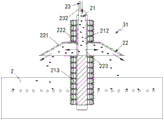
further, as shown in fig. 23 to 25, the first transmission assembly 31 includes a rotation assembly 21 disposed at a lower end portion of the dip tank body 2 and located in the impurity discharge space 203, a bubble removing assembly 22 disposed on the rotation assembly 21 and used for spraying liquid into the dip tank body 2, and a temperature reducing assembly 23 having one end communicating with the bubble removing assembly 22;
the rotating assembly 21 comprises a bracket 211 arranged on the dipping tank body 2, a driving shaft a212 rotatably arranged on the bracket 211 and a turbine 213 which is coaxial with and fixedly connected with the lower end of the driving shaft a212, wherein the turbine 213 is used for driving water at the lower end of the dipping tank body 2 to flow back to the gluing space 202 from the impurity discharge space 203, a transmission gear a214 and a transmission gear b215 which is rotatably arranged on the bracket 211 and is meshed with the transmission gear a214 are arranged on the driving shaft a212, and the transmission gear b215 is driven by a driving motor to rotate circumferentially;
the de-bubbling assembly 22 comprises a wide-mouth shed 221 arranged at the lower end of the driving shaft a212, the transmission gear a214 is positioned above the wide-mouth shed 221, the driving shaft a212 is arranged in a hollow structure, the lower end of the driving shaft a is provided with a circular groove 222, and the wide-mouth shed 221 and the circular groove 222 are fixedly connected through a connecting rod 223;
the cooling assembly 23 includes a material storage box 231 disposed at the outer end of the glue dipping tank body 2, a connecting pipe a232 having one end communicated with the material storage box 231 and the other end disposed at the upper end of the driving shaft a212, and a connecting pipe b233 having one end communicated with the first collecting tank 523 and the other end communicated with the material storage box 231, wherein a cooling medium 234 is sleeved outside the connecting pipe b233, and the connecting pipe a232 transmits the glue solution in the material storage box 231 to the driving shaft a212 through the pump body.
In this embodiment, through setting up the subassembly 21 that circles round for turbine 23 is rotating the in-process, can be with the colloid transmission that is located the steeping vat cell body 2 bottom to the upper end of steeping vat cell body 2, and the colloid that is located the upper end flows to from in impurity discharge space 203 under the action of gravity, and then accomplishes the backward flow work of whole colloid at steeping vat cell body 2.
In detail, the driving motor drives the transmission gear b215 to rotate, the rotating transmission gear b215 drives the transmission gear a214 to rotate, the rotating transmission gear a214 drives the driving shaft a212 to rotate, then, the driving shaft a212 drives the turbine 213 to transmit, and the colloid at the bottom of the dipping tank body 2 is transmitted to the upper end of the dipping tank body 2.
In this embodiment, by arranging the bubble removing assembly 22 and matching the cooling assembly 23, a part of the colloid with higher temperature after the gluing operation is completed is pushed out to complete the cooling operation, and is recycled into the material storage box 231 after the cooling operation is completed, so that the utilization rate of raw materials is high; the other part of colloid is beneficial to mixing with the new colloid which is continuously added after discharging a part of colloid, and is beneficial to the temperature difference of the new colloid and the old colloid to finish the cooling work of the old colloid after the mixing work, meanwhile, the addition of the new colloid is also the filling work of the colloid which is reduced after the gluing work in the glue dipping groove body 2, in addition, the sprayed liquid adopts a centrifugal wide mouth to throw out the colloid which is matched with the transmission under the action of a turbine, the complete bubble removing work of bubbles attached to the upper surface of the colloid is realized, the quality of the product is further improved, and the occurrence of pinholes of gloves is avoided.
In detail, the colloid discharged from the first collecting tank 523 enters the storage tank 231 through the connecting pipe b233, and during the transmission process, the cooling medium 234 cools the colloid in the connecting pipe b233, and then the colloid in the storage tank 231 is output from the connecting pipe a232 to the driving shaft a212 through the pump body, and during the circumferential process of the driving shaft a212, the colloid at the bottom is centrifugally thrown out to the glue dipping tank body 2 under the guidance of the wide-mouth shed 221, is mixed with the colloid in the glue dipping tank body 2, and simultaneously punctures the bubbles on the upper surface of the glue dipping tank body 2.
Further, as shown in fig. 9, the second transmission assembly 32 includes a bracket b321 disposed on the dip tank body 2, a driving shaft b322 rotatably disposed on the bracket b321, and a turbine b coaxially and fixedly connected with the lower end of the driving shaft b322, and the driving shaft b322 and the driving shaft a22 are in synchronous transmission connection through a plurality of sets of synchronous belts;
the upper end of the driving shaft b322 is provided with a heat dissipating blade 323, and the heat dissipating blade 323 performs physical cooling operation on the hand membrane 123 during transmission.
In the embodiment, by arranging the second transmission assembly 32, on one hand, the second transmission assembly 32 is used for pumping the colloid in the upstream state, so that the problem of insufficient power for conveying the colloid passing through the two horizontal parts to the upper end of the glue dipping groove body 2 is avoided, and in addition, the heat dissipation blades 323 are used for synchronous transmission, so that the physical cooling work for the hand membrane 123 in transmission is completed, the overhigh temperature of the hand membrane 123 is avoided, and the product quality is further improved; the structure is simple, additional power is saved, production is reduced, cooling is completed, and pumping work of the upflow colloid is promoted.
In detail, the driving shaft b322 is synchronously driven with the driving shaft a22 through a synchronous belt, the driving shaft b322 drives the turbine b to be synchronously driven, the power supply effect on the upward flowing colloid pumping is completed, and meanwhile, the heat dissipation blades 323 rotating on the driving shaft b complete the hand membrane cooling work in the transmission process.
The working process is as follows:
the chain mechanism 205 drives the cleaning mechanism 4, so that the cleaning mechanism 4 finishes the automatic cleaning work on the bottom of the impregnation tank body 2 in the process that the colloid flows along the impregnation tank body 2 for a circle;
when the brush roll 48 moves to the first discharging assembly 51, the chain mechanism 205 stops working at the moment, the distance sensor drives the horizontal pushing cylinder 511 to automatically start, the limiting plate 513 moves to the bottom of the gum dipping groove body 2, impurities are blocked by the limiting plate 513, colloid is output through a filter screen part of the limiting plate 513, then the telescopic unit a512 continuously extrudes, the telescopic unit a512 drives the driving gear a5172 to rotate through the driving rack a5171, the rotating driving gear a5172 drives the driving rack b5174 to act on the telescopic unit a512, the pushing cylinder 514 discharges sediment in front of the brush roll 48, after the pushing cylinder 514 enters the protruding platform 521, the control door 522 automatically opens, the colloid and the impurities enter the first collecting box 523 together, the glue under the filter plate 524 is collected, and the impurities on the filter plate 524 are collected;
the guide rail 131 drives the glove module 12 to downwards drive along the inclined planes of the first inclined part 20a, the second inclined part 20c and the third inclined part 20e, and simultaneously, the guide rail 131 drives the glove module 12 to downwards move along the horizontal parts of the first horizontal part 20b and the second horizontal part 20d into the dipping groove body 2 to complete pre-gluing work and gluing work; meanwhile, after the driven gear 133 moves to the driving rack 134, the driven gear rotates under the driving of the driving rack 134, and the gluing operation is uniform in the gluing process; when the glove module 12 is positioned in the first horizontal part 20b, the pre-gluing work of the glove module 12 is used as a material sticking mode, meanwhile, the driving shaft b322 is in synchronous transmission with the driving shaft a22 through a synchronous belt, the driving shaft b322 drives the turbine b to perform synchronous transmission to finish the power supply effect on the pumping of the upward flowing colloid, and meanwhile, the heat dissipation blades 323 rotating on the driving shaft finish the hand film cooling work in the transmission process;
the colloid discharged from the first collecting box 523 enters the storage box 231 through the connecting pipe b233, during the transmission process, the cooling medium 234 cools the colloid in the connecting pipe b233, then the colloid in the storage box 231 is output from the connecting pipe a232 to the driving shaft a212 through the pump body, the driving shaft a212 is in the circumferential process, the colloid at the bottom is centrifugally thrown out to the glue dipping tank body 2 under the guidance of the wide-mouth shed 221, the colloid is mixed with the colloid in the glue dipping tank body 2, meanwhile, the bubbles on the upper surface of the glue dipping tank body 2 are punctured, and finally the colloid with the standard temperature is reused to the glue applying space 202 as the stock solution for gluing work.
In the description of the present invention, it is to be understood that the terms "front-back", "left-right", and the like indicate orientations or positional relationships based on those shown in the drawings, and are only for convenience in describing the present invention and simplifying the description, but do not indicate or imply that the referred device or component must have a specific orientation, be constructed in a specific orientation, and be operated, and thus should not be construed as limiting the invention.
Of course, in this disclosure, those skilled in the art will understand that the terms "a" and "an" should be interpreted as "at least one" or "one or more," i.e., in one embodiment, a number of an element may be one, and in another embodiment, a number of the element may be plural, and the terms "a" and "an" should not be interpreted as limiting the number.
The above description is only for the preferred embodiment of the present invention, but the scope of the present invention is not limited thereto, and any changes or substitutions that can be easily made by those skilled in the art in light of the technical teaching of the present invention should be included within the scope of the present invention. Therefore, the protection scope of the present invention shall be subject to the protection scope of the claims.
Claims (10)
1. The nitrile butadiene rubber cement gluing process of the low temperature resistant nitrile butadiene protective gloves is characterized by comprising the following steps of:
firstly, in a first glue injection process, an outlet valve of a material storage box body (231) is enlarged, glue in the material storage box body (231) is output into a driving shaft a (212) from a connecting pipe a (232) through a pump body, and flows into a glue dipping groove body (2) until the glue dipping groove body (2) is filled with glue;
step two, a hand membrane cooling process, wherein the guide track (131) drives the glove module (12) to downwards transmit along the inclined planes of the first inclined part (20a), the second inclined part (20c) and the third inclined part (20e) in parallel, the driving shaft b (322) is synchronously transmitted with the driving shaft a (22) through a synchronous belt, the driving shaft b (322) drives the turbine b to synchronously transmit, the power supply effect on the upward flow colloid pumping is completed, and meanwhile, the heat dissipation blades (323) rotating on the driving shaft b finish the hand membrane cooling work in the transmission process;
step three, a hand membrane pre-gluing process, wherein glue in the gluing space (202) flows from bottom to top, the temperature of the glue in the second horizontal part (20d) is increased after the glue is glued and flows into the first horizontal part b (20), and the guide rail (131) drives the glove module (12) to move downwards along the first horizontal part b (20) to the inside of the glue dipping groove body (2) to complete pre-gluing work;
step four, the glove module (12) is driven by the guide rail (131) to move downwards along the horizontal part of the second horizontal part (20d) to the dipping groove body (2) to finish the gluing work in the process of completely gluing the hand membrane;
step five, in the step of cleaning the body of the impregnation tank, the chain mechanism (205) drives the cleaning mechanism (4) to enable the cleaning mechanism (4) to finish the automatic cleaning work of the bottom of the body of the impregnation tank (2) in the process that the colloid flows along the body of the impregnation tank (2) for a circle;
sixthly, impurity discharging, wherein when the brush roller (48) moves to the first discharging assembly (51), at the moment, the chain-driven mechanism (205) stops working, the distance sensor drives the horizontal pushing cylinder (511) to automatically start, the limiting plate (513) moves to the bottom of the glue dipping tank body (2), impurities are blocked by the limiting plate (513), and colloid is output through a filter screen part of the limiting plate (513), then the telescopic unit a (512) continues to extrude, the telescopic unit a (512) acts on the telescopic unit a (512) through a translation piece (517), the push-out cylinder (514) discharges sediments in front of the brush roller (48), after the push-out cylinder (514) enters the protruding platform (521), the control door (522) is automatically opened, the colloid and the impurities enter the first collecting box (523) together, the colloid below the filter plate (524) is collected, and the impurities above the filter plate (524) are collected;
step seven, completing the colloid cooling circulation process after gluing, enabling the colloid discharged from the first collecting box (523) to enter the material storage box body (231) through the connecting pipe b (233), and completing the colloid cooling work in the connecting pipe b (233) by the cooling medium (234) in the transmission process;
step eight, a new colloid supplementing process, wherein the colloid in the storage box body (231) is output into the driving shaft a (212) from the connecting pipe a (232) through the pump body, the colloid at the bottom is centrifugally thrown out to the glue dipping groove body (2) under the guidance of the wide-mouth shed (221) in the circumferential process of the driving shaft a (212) and is mixed with the colloid in the glue dipping groove body (2), and finally the colloid with the temperature reaching the standard is recycled to the glue dipping space (202) to be used as a stock solution for gluing work;
and step nine, a bubble removing process, which is synchronous with the step eight, wherein the colloid at the bottom is centrifugally thrown out to the upper surface of the glue dipping tank body (2) under the guidance of the wide-mouth shed (221), and bubbles on the upper surface of the glue dipping tank body (2) are punctured.
2. The butyronitrile glue sizing process of the low temperature resistant butyronitrile protective glove according to claim 1, characterized in that a temperature sensor is adopted in the latex temperature detection mode in the dipping tank body (2).
3. The nitrile-butadiene rubber cement gluing process for the low-temperature-resistant nitrile-butadiene protective gloves according to claim 1, wherein in the first step, the temperature of the latex in the dipping tank body (2) is 20-28 ℃.
4. The process for gumming nitrile rubber cement for low temperature resistant nitrile protective gloves according to claim 1, wherein the latex temperature in the first horizontal portion (20b) is between 26 and 28 ℃.
5. The nitrile-butadiene rubber cement sizing process for the low-temperature-resistant nitrile-butadiene protective gloves according to claim 1, wherein the temperature of the latex in the material storage box (231) is 18-20 ℃.
6. The process for gumming nitrile rubber cement for low temperature resistant nitrile protective gloves according to claim 1, wherein the temperature of the latex in the third inclined portion (20e) is 22-24 ℃.
7. The nitrile-butadiene rubber cement sizing process for the low-temperature-resistant nitrile-butadiene protective gloves according to claim 1, characterized in that the temperature of the glove modules (12) before entering the dipping tank body (2) is 80-85 ℃.
8. The process for the sizing of nitrile cement for low temperature resistant nitrile protective gloves according to claim 1 wherein the temperature of the glove module (12) after entering the first horizontal portion (20b) is between 75 ℃ and 80 ℃.
9. The process for the sizing of nitrile cement for low temperature resistant nitrile protective gloves according to claim 1 wherein the temperature of the glove module (12) after entering the second horizontal portion (20b) is between 60 ℃ and 75 ℃.
10. The butyronitrile rubber sizing process of the low temperature resistant butyronitrile protective glove in the step two is characterized in that the rotating speed of the turbine b is 89 r/min.
Priority Applications (1)
| Application Number | Priority Date | Filing Date | Title |
|---|---|---|---|
| CN202110194668.4A CN112974179A (en) | 2021-02-21 | 2021-02-21 | Nitrile butadiene rubber cement sizing process of low-temperature-resistant nitrile butadiene protective gloves |
Applications Claiming Priority (1)
| Application Number | Priority Date | Filing Date | Title |
|---|---|---|---|
| CN202110194668.4A CN112974179A (en) | 2021-02-21 | 2021-02-21 | Nitrile butadiene rubber cement sizing process of low-temperature-resistant nitrile butadiene protective gloves |
Publications (1)
| Publication Number | Publication Date |
|---|---|
| CN112974179A true CN112974179A (en) | 2021-06-18 |
Family
ID=76394067
Family Applications (1)
| Application Number | Title | Priority Date | Filing Date |
|---|---|---|---|
| CN202110194668.4A Withdrawn CN112974179A (en) | 2021-02-21 | 2021-02-21 | Nitrile butadiene rubber cement sizing process of low-temperature-resistant nitrile butadiene protective gloves |
Country Status (1)
| Country | Link |
|---|---|
| CN (1) | CN112974179A (en) |
Cited By (1)
| Publication number | Priority date | Publication date | Assignee | Title |
|---|---|---|---|---|
| CN114405713A (en) * | 2021-12-16 | 2022-04-29 | 盐城科奥机械有限公司 | Suspension chain type workpiece rust prevention treatment assembly line |
-
2021
- 2021-02-21 CN CN202110194668.4A patent/CN112974179A/en not_active Withdrawn
Cited By (1)
| Publication number | Priority date | Publication date | Assignee | Title |
|---|---|---|---|---|
| CN114405713A (en) * | 2021-12-16 | 2022-04-29 | 盐城科奥机械有限公司 | Suspension chain type workpiece rust prevention treatment assembly line |
Similar Documents
| Publication | Publication Date | Title |
|---|---|---|
| CN110013930B (en) | Special coating glass fiber cloth preparation is with coating equipment | |
| CN112974179A (en) | Nitrile butadiene rubber cement sizing process of low-temperature-resistant nitrile butadiene protective gloves | |
| CN113843917A (en) | Production process of regenerated granules from waste nylon yarns | |
| CN112895263A (en) | Butyronitrile ultra-thin antiskid labor protection gloves making devices | |
| CN112974129B (en) | Automatic temperature control device is used in production of butyronitrile antiskid gloves | |
| CN214554152U (en) | Waste recycling device for processing plastic bottles | |
| CN109330536B (en) | Shoe cover cleaning system | |
| CN112974130B (en) | Automatic gluing equipment for butyronitrile gloves | |
| CN113070990B (en) | Mud cutting equipment for processing ceramic products | |
| CN114192471A (en) | A belt cleaning device for abandonment plastics are retrieved and are used | |
| CN112974131B (en) | Self-cleaning device for sizing nitrile gloves | |
| CN114161617A (en) | Automatic environment-friendly waste plastic crushing device with cleaning function | |
| CN108941125B (en) | External cleaning device for barreled water bucket | |
| CN216181910U (en) | Waste plastic bottle reprocessing cleaning mechanism capable of performing cold and hot washing | |
| CN115365220B (en) | Plastic particle cleaning device and method | |
| CN215936126U (en) | Automatic fish washer of ejection of compact | |
| CN213353134U (en) | Waste plastic reprocessing cleaning device with water circulation function | |
| CN220116424U (en) | Glass manufacturing device | |
| CN111844584B (en) | Casting machine for ultra-high molecular weight polyethylene film and preparation method thereof | |
| CN211569591U (en) | Water-cooling brace conveyor | |
| CN108000693A (en) | Automatic cleaning die device | |
| CN220192103U (en) | Full-automatic high-efficiency string-label and pill-cutting integrated equipment | |
| CN215151286U (en) | Injection molding machine capable of conveniently cleaning feeding device | |
| CN219519790U (en) | Mica washs edulcoration machine | |
| CN113001847A (en) | Preparation method of butyronitrile gloves |
Legal Events
| Date | Code | Title | Description |
|---|---|---|---|
| PB01 | Publication | ||
| PB01 | Publication | ||
| SE01 | Entry into force of request for substantive examination | ||
| SE01 | Entry into force of request for substantive examination | ||
| WW01 | Invention patent application withdrawn after publication | ||
| WW01 | Invention patent application withdrawn after publication |
Application publication date: 20210618 |