CN112968393A - Stay wire tool - Google Patents
Stay wire tool Download PDFInfo
- Publication number
- CN112968393A CN112968393A CN202110143436.6A CN202110143436A CN112968393A CN 112968393 A CN112968393 A CN 112968393A CN 202110143436 A CN202110143436 A CN 202110143436A CN 112968393 A CN112968393 A CN 112968393A
- Authority
- CN
- China
- Prior art keywords
- rod
- moving rod
- screw
- wire
- limiting
- Prior art date
- Legal status (The legal status is an assumption and is not a legal conclusion. Google has not performed a legal analysis and makes no representation as to the accuracy of the status listed.)
- Granted
Links
Images


Classifications
-
- H—ELECTRICITY
- H02—GENERATION; CONVERSION OR DISTRIBUTION OF ELECTRIC POWER
- H02G—INSTALLATION OF ELECTRIC CABLES OR LINES, OR OF COMBINED OPTICAL AND ELECTRIC CABLES OR LINES
- H02G1/00—Methods or apparatus specially adapted for installing, maintaining, repairing or dismantling electric cables or lines
- H02G1/02—Methods or apparatus specially adapted for installing, maintaining, repairing or dismantling electric cables or lines for overhead lines or cables
Abstract
The invention relates to a wire bracing tool, comprising: the side wall of the gear fixing seat is provided with a first mounting hole, at least one shaft end vertical to the side wall is provided with a second mounting hole, a driving gear is fixedly mounted in the first mounting hole, a transmission gear is mounted in the second mounting hole, and the driving gear is meshed with the transmission gear; the output end of the driving component is connected with the driving gear and is used for driving the driving gear to rotate; the screw transmission mechanism comprises a screw rod and a connecting seat sleeved on the screw rod, one end of the screw rod is connected with the transmission gear, and the connecting seat is sleeved on the screw rod; the moving rod is sleeved outside the screw rod, one end of the moving rod is fixedly connected with the connecting seat, and at least one wire supporting frame is fixedly installed at the other end of the moving rod. The wire supporting tool can increase the distance between the adjacent loop wires under the condition of electrification, and does not change the interval between the adjacent wires of the same loop.
Description
Technical Field
The invention relates to the technical field of live working, in particular to a wire supporting tool.
Background
With the rapid development of national economy and the continuous acceleration of the pace of urbanization, the expectation of users on uninterrupted power supply is higher and higher, and the improvement of the power supply reliability becomes an important task of power supply enterprises. The live working of the power distribution network is vigorously carried out, and the power distribution network is overhauled and maintained in a live working mode as far as possible, so that the power supply reliability is improved, and meanwhile, more economic benefits and social benefits of power supply enterprises in the power market can be obtained.
In electrified pole setting work project, need strut the wire distance of pole setting position department as far as possible, make alternate distance increase, pass between the wire more easily at pole setting in-process pole like this to reduce the risk that the pole collided the wire.
Particularly for the double-loop triangular arrangement, the inter-phase distance of the double-loop triangular arrangement circuit is relatively small, especially the inter-phase distance of the two lower phase wires is very close, and great risk exists in the operation process, so that the inter-phase distance of the wires between the same loops needs to be kept unchanged while the wires are separated, and danger caused by the change of the inter-phase distance is prevented.
Disclosure of Invention
In view of the above, there is a need to provide a wire supporting tool for solving the problem of increasing the distance between two adjacent wires during live working.
The invention provides a wire supporting tool, comprising:
the side wall of the gear fixing seat is provided with a first mounting hole, and at least one shaft end vertical to the side wall is provided with a second mounting hole;
the driving component comprises a driver, a driving gear and a transmission gear, the driving gear is fixedly arranged in the first mounting hole, the transmission gear is fixedly arranged in the second mounting hole, the output end of the driver is connected with the driving gear and used for driving the driving gear to rotate, and the driving gear is meshed with the transmission gear;
the screw transmission mechanism comprises a screw rod and a connecting seat sleeved on the screw rod, one end of the screw rod is connected with the transmission gear, and the connecting seat is sleeved on the screw rod;
the moving rod is sleeved outside the screw rod, and one end of the moving rod is fixedly connected with the connecting seat;
and the wire support frame is fixedly arranged at the other end of the moving rod.
Furthermore, the right end of the gear fixing seat is provided with the second mounting hole, the transmission gear is fixedly mounted in the second mounting hole at the right end, and the driving gear is meshed with the transmission gear; the stay wire tool further comprises:
the left stay bar is fixedly connected with the left end of the gear fixing seat, and at least one wire supporting frame is fixedly mounted on the left stay bar.
Further, the bracing wire tool further comprises:
the right support rod is fixedly connected with the right end of the gear fixing seat and sleeved outside the moving rod, the length of the right support rod is smaller than that of the moving rod, the right end of the moving rod extends out of the right end of the right support rod, and the wire support frame is installed on the part of the moving rod extending out of the right support rod;
the limiting mechanism comprises a limiting screw, a limiting seat sleeve and a long and thin groove which is formed in the length direction of the moving rod, the limiting seat sleeve is arranged on the moving rod, one end of the limiting seat sleeve is fixedly arranged at the right end of the right supporting rod, the limiting screw is fixed on the limiting seat sleeve, the bottom of the limiting screw is inserted into the groove, and the moving rod slides along the groove in the moving process.
Furthermore, second mounting holes are formed in the left end and the right end of the gear fixing seat, the transmission gears are mounted in the two second mounting holes, and the driving gear and the left end and the right end of the driving gear are meshed with the transmission gear at the left end and the transmission gear at the right end respectively;
the screw transmission mechanism comprises a left screw transmission mechanism and a right screw transmission mechanism, the left screw transmission mechanism comprises a left screw and a first connecting seat sleeved on the left screw, one end of the left screw is connected with the transmission gear at the left end, and the first connecting seat is sleeved on the left screw; the right screw transmission mechanism comprises a right screw rod and a second connecting seat sleeved on the right screw rod, one end of the right screw rod is connected with the transmission gear at the right end, and the second connecting seat is sleeved on the right screw rod;
the moving rod comprises a left moving rod and a right moving rod, one end of the left moving rod is fixedly connected with the first connecting seat, and the other end of the left moving rod is fixedly provided with at least one wire supporting frame; one end of the right moving rod is fixedly connected with the second connecting seat, and the other end of the right moving rod is fixedly provided with at least one wire supporting frame.
Further, the bracing wire tool further comprises:
the left support rod is sleeved outside the left moving rod, one end of the left support rod is fixedly connected with the left end of the gear fixing seat, the length of the left support rod is smaller than that of the left moving rod, the left end of the left moving rod extends out of the left end of the left support rod, and the wire support frame is fixedly installed on the part of the left moving rod extending out of the left support rod;
the right support rod is sleeved outside the right moving rod, one end of the right support rod is fixedly connected with the right end of the gear fixing seat, the length of the right support rod is smaller than that of the right moving rod, the right end of the right moving rod extends out of the left end of the right support rod, and the wire support frame is fixedly installed on the part of the right moving rod extending out of the right support rod;
the left limiting mechanism comprises a left limiting screw, a left limiting seat sleeve and a slender groove formed in the length direction of the left moving rod, the left limiting seat sleeve is sleeved on the left moving rod, one end of the left limiting seat sleeve is fixedly installed at the left end of the left supporting rod, the left limiting screw is fixed on the left limiting seat sleeve, the bottom of the left limiting screw is inserted into the groove in the left moving rod, and the left limiting screw slides along the groove in the moving process of the moving rod;
the right limiting mechanism comprises a right limiting screw, a right limiting seat sleeve and a long and thin groove which is formed in the length direction of the right moving rod, the right limiting seat sleeve is arranged on the right moving rod, one end of the right limiting seat sleeve is fixedly arranged at the right end of the right support rod, the right limiting screw is fixed on the right limiting seat sleeve, the bottom of the right limiting screw is inserted into the groove in the right moving rod, and the right moving rod slides along the groove in the moving process.
Further, fixed mounting has two wire support frames on the left vaulting pole, two wire support frame interval sets up, fixed mounting has two wire support frames on the carriage release lever, distance between two wire support frames on the carriage release lever equals the distance of two direction support frames on the left vaulting pole.
Further, two wire support frames are fixedly mounted on the left moving rod and the right moving rod, and the distance between the two wire support frames on the left moving rod is equal to the distance between the two wire support frames on the right moving rod.
Further, the screw transmission mechanism further comprises a connecting piece, and the lead screw is fixedly connected with the transmission gear through the connecting piece.
Further, the driver is a driving handle or a driving motor.
Furthermore, the stay wire tool further comprises a cover plate, wherein the cover plate is fixed on the side wall of the gear fixing seat and used for sealing the driving gear and the transmission gear in the gear fixing seat.
The wire supporting tool provided by the invention can achieve the following technical effects:
1. when the wire supporting tool is used, a wire is placed in the wire supporting frame to be fixed, the driving gear is driven to rotate through the driving part, the driving gear drives the transmission gear to rotate, the transmission gear rotates to drive the lead screw to rotate, and the lead screw rotates to drive the wire supporting frame to move along the horizontal direction, so that the increase of the interval of the wire is realized.
2. The invention further arranges the left stay bar, fixedly arranges two lead support frames with a certain distance on the left stay bar, arranges the spiral transmission mechanism at the right end of the gear fixing seat, fixedly arranges the two lead support frames at the right end of the movable bar, and arranges the two leads of the left loop in the two lead support frames at the left side for fixing aiming at the situation of double-loop triangular arrangement, the two leads of the right loop are arranged in the two lead support frames at the right side for fixing, and the two lead support frames at the right side drive the leads to move towards the right side through the driving action of the driving part, thereby increasing the distance between the two loop leads at the bottom of the two loops, and simultaneously, the distance between the two lead support frames of the same loop is not changed during moving, thus improving the safety of live working.
Drawings
Fig. 1 is a schematic structural diagram of a wire bracing tool according to an embodiment of the present invention;
FIG. 2 is a schematic view of the structure of FIG. 1 with the right brace and travel bar removed;
FIG. 3 is an exploded view of FIG. 1;
FIG. 4 is a schematic structural view of the spacing mechanism of FIG. 1;
FIG. 5 is a schematic structural view of an embodiment of a gear holder;
FIG. 6 is a schematic structural view of a wire support bracket;
in the figure:
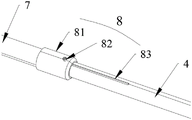
the device comprises a gear fixing seat 1, a driving handle 2, a screw transmission mechanism 3, a movable rod 4, a lead wire support frame 5, a left support rod 6, a right support rod 7, a limiting seat sleeve 8, a plug 9, a first mounting hole 11, a second mounting hole 12, a cover plate 13, a driving handle 21, a driving gear 22, a transmission gear 23, a lead screw 31, a connecting seat 32, a connecting piece 33, a limiting seat sleeve 81, a limiting screw 82 and a groove 83.
Detailed Description
The accompanying drawings, which are incorporated in and constitute a part of this application, illustrate preferred embodiments of the invention and together with the description, serve to explain the principles of the invention and not to limit the scope of the invention.
Referring to fig. 1, 2 and 5, an embodiment of the present invention provides a wire supporting tool, which includes a gear fixing base 1, a driving part 2, a screw transmission mechanism 3, a moving rod 4 and at least one wire supporting frame 5.
A first mounting hole 11 is formed in the side wall of the gear fixing seat 1, and a second mounting hole 12 is formed in one end, perpendicular to the side wall, of the gear fixing seat. The driving part 2 comprises a driving handle 21, a driving gear 22 and a transmission gear 23, the driving gear 21 is fixedly installed in the first installation hole 11, the transmission gear 23 is fixedly installed in the second installation hole 12, the output end of the driving handle 21 is connected with the driving gear 22 and used for driving the driving gear 22 to rotate, and the driving gear 22 is meshed with the transmission gear 23. The screw transmission mechanism 3 comprises a screw rod 31 and a connecting seat 32 sleeved on the screw rod 31, one end of the screw rod 31 is connected with the transmission gear 23, and the connecting seat 32 is sleeved on the screw rod 31; the moving rod 4 is sleeved outside the screw rod 31, one end of the moving rod is fixedly connected with the connecting seat 32, and the other end of the moving rod 4 is fixedly provided with at least one wire supporting frame 5.
When the distance between two adjacent wires needs to be increased, the wires on one side are placed in the wire support frame 5, the driving handle 21 drives the driving gear 22 to rotate, the driving gear 22 drives the transmission gear 23 to rotate, the transmission gear 23 rotates to drive the lead screw 31 to rotate, and the lead screw 31 rotates to drive the wire support frame 5 to move along the horizontal direction, so that the increase of the wire interval is realized.
It should be noted that the number of the wire support frames 5 may be one or more, and specifically, the number of the wires to be removed may be determined according to the number of the wires to be removed, when the wires are horizontally arranged for the dual loop, three wire support frames 5 are fixedly mounted on the moving rod 4, and the three wire support frames 5 are arranged at intervals. When the two wires are arranged in a triangular mode, when the distance between two adjacent groups of wires of two loops at the bottom needs to be increased, the number of the wire support frames 5 is two, and therefore the two wires on one side between the two loops at the bottom move towards the right side. When the wire support frames 5 are two or three, the distance between two adjacent moved wires is kept unchanged, so that the purpose of increasing the distance between the wires is realized, and the change of the distance between two adjacent moved wires is avoided, thereby improving the safety of live working.
The driving gear 22 and the transmission gear 23 are both bevel gears, and the driving gear 22 and the transmission gear 23 are both fixedly installed in the gear fixing seat 1 through bearings.
As shown in fig. 3, in order to further improve the reliability of the operation and prevent the distance between two adjacent wires from moving during the operation, the second mounting hole 12 is formed at the right end of the gear fixing seat, a driving gear 22 is fixedly mounted in the first mounting hole 11, a transmission gear 23 is mounted in the second mounting hole 12, and the driving gear 22 is engaged with the transmission gear 23. The stay wire tool further comprises a left stay bar 6, the left stay bar 6 is fixedly connected with the left end of the gear fixing seat 1, and at least one wire supporting frame 5 is fixedly mounted on the left stay bar 6.
Through the left stay bar 6 of the left end fixed connection of gear fixing base 1, fixed mounting has at least one wire support frame 5 on the stay bar 6 of a left side, will screw drive mechanism 3 sets up on the right side, and fixed mounting has at least one wire support frame 5 on the carriage release lever 4. Therefore, when the wire fixing device is used, a left wire is placed in the wire support frame 5 on the left support rod 6 to be fixed, a right wire is placed in the wire support frame 5 on the moving rod 4 on the right side to be fixed, and the driving handle 21 is rotated, so that the wire support frame 5 on the right side moves to the right side, and the distance between every two adjacent wires is increased. The number of the wire support frames 5 on the left support rod 6 is the same as that of the wire support frames 5 on the right support rod 7, and the wire support frames can be set to be one or multiple, when the wire support frames are set to be multiple, the interval between two loops can be increased, meanwhile, the distance between two adjacent wires of the same loop can be kept unchanged, and the safety of live working is improved. The left side wire can be fixed through the arrangement of the left support rod, and the wire is prevented from being moved in the operation process.
Combine fig. 3 and fig. 4, for right the distance of the removal of carriage release lever 4 carries out better control, the stay wire instrument still includes right vaulting pole 7 and stop gear 8, right vaulting pole 7 with the right-hand member fixed connection of gear fixing base 4, and the cover is established the carriage release lever 4 outside, right vaulting pole 7's length is less than carriage release lever 4's length, carriage release lever 4's right-hand member is followed right-hand member of right vaulting pole 7 stretches out, wire support frame 5 is installed carriage release lever 4 stretches out on the part of right vaulting pole 7. Stop gear 8 includes stop screw 82, spacing seat cover 81 and along the long and thin recess 83 that the length direction of carriage release lever 4 was seted up, spacing seat 81 cover is established on carriage release lever 4, and one end fixed mounting be in the right-hand member of right stay bar 7, stop screw 82 fixes on the spacing seat cover 81, stop screw 82's bottom is inserted and is established in the recess 83, and is in the in-process that carriage release lever 4 removed along recess 83 slides.
When the driving handle 21 is rotated, the moving rod 4 moves to one side along with the rotation of the driving handle 21, so that the wire support frame 5 is driven and wires fixed in the wire support frame 5 move to one side, after the moving rod 4 moves to a certain degree, namely, after the interval between adjacent wires reaches the required distance, the limiting screw 82 slides to the end part of the groove 83 to prop against the groove 83, so that the limiting is realized.
As another embodiment of the present invention, the screw transmission mechanism 3 includes a left screw transmission mechanism and a right screw transmission mechanism, the left screw transmission mechanism includes a left screw and a first connection seat sleeved on the left screw, one end of the left screw is connected to the transmission gear at the left end, and the first connection seat is sleeved on the left screw; the right screw transmission mechanism comprises a right screw rod and a second connecting seat sleeved on the right screw rod, one end of the right screw rod is connected with the transmission gear at the right end, the second connecting seat is sleeved on the right screw rod, and the screw directions of the left screw rod and the right screw rod are opposite. The moving rod comprises a left moving rod and a right moving rod, one end of the left moving rod is fixedly connected with the first connecting seat, and the other end of the left moving rod is fixedly provided with at least one wire supporting frame; one end of the right moving rod is fixedly connected with the second connecting seat, and the other end of the right moving rod is fixedly provided with at least one wire supporting frame.
When the wire supporting tool is used, the driving handle rotates to drive the transmission gears at the two ends to rotate at the same time, so that the spiral transmission mechanisms at the two sides can be driven to rotate at the same time. Therefore, the wires on the two sides move in opposite directions at the same time, and the wire supporting efficiency is improved.
To further facilitate control of the distance of movement of the left and right wires,
the stay wire tool further comprises a left stay bar, a right stay bar, a left limiting mechanism and a right limiting mechanism. The left support rod is sleeved outside the left moving rod, one end of the left support rod is fixedly connected with the left end of the gear fixing seat, the length of the left support rod is smaller than that of the left moving rod, the left end of the left moving rod extends out of the left end of the left support rod, and the wire support frame is fixedly installed on the part of the left moving rod extending out of the left support rod; the right support rod is sleeved outside the right moving rod, one end of the right support rod is fixedly connected with the right end of the gear fixing seat, the length of the right support rod is smaller than that of the right moving rod, the right end of the right moving rod extends out of the left end of the right support rod, and the wire support frame is fixedly installed on the portion, extending out of the right support rod, of the right moving rod. The left limiting mechanism comprises a left limiting screw, a left limiting seat sleeve and a long and thin groove which is formed in the length direction of the left moving rod, the left limiting seat sleeve is arranged on the left moving rod, one end of the left limiting seat sleeve is fixedly arranged at the left end of the left support rod, the left limiting screw is fixed on the left limiting seat sleeve, the bottom of the left limiting screw is inserted into the groove in the left moving rod, and the moving rod slides along the groove in the moving process. The right limiting mechanism comprises a right limiting screw, a right limiting seat sleeve and a long and thin groove formed in the length direction of the right moving rod, the right limiting seat sleeve is arranged on the right moving rod, one end of the right limiting seat sleeve is fixedly arranged at the right end of the right support rod, the right limiting screw is fixed on the right limiting seat sleeve, the bottom of the right limiting screw is inserted into the groove in the right moving rod, and the right moving rod slides along the groove in the moving process.
When the wire rods on the two sides and the wire fixing seats fixed on the wire rods move to a certain position, the first connecting seat is limited through the matching of the left limiting screw and the groove, and the second connecting seat is limited through the right limiting screw, so that the left moving rod and the right moving rod are prevented from further moving towards the two sides.
In the embodiment, the number of the wire support frames fixed on the left and right moving rods on one side can be one or more, and when the number of the wire support frames is two or three, the distance between two wires of the same adjacent loop can be further kept unchanged, so that the safety of live-wire work is further improved.
It should be noted that, in the above-mentioned embodiment, the driving handle 21 may be replaced by a driving motor or a rotary cylinder.
In order to prolong the service life of the driving gear 22 and the transmission gear 23 and prevent dust or impurities from entering the gear fixing seat 1 and wearing the driving gear 22 and the driven gear 23, the wire supporting tool further comprises a cover plate 13, and the cover plate 13 is fixed on the side wall of the gear fixing seat 1 and used for sealing the driving gear 22 and the transmission gear 23 in the gear fixing seat 1.
The wire support frame 5 comprises a connecting portion 51 and a supporting portion 52, the connecting portion 51 is fixedly connected with the left support rod 6 or the moving rod 4 through a bolt 53, and the supporting portion 51 is used for supporting and fixing the wire. The supporting portion 52 comprises a U-shaped supporting frame 521 and a clamping member 522 fixed on one side of the supporting portion 52, the clamping member 522 is rotatably connected with one side of the U-shaped supporting frame 521 through a rotating shaft 523, the clamping member 522 comprises a handle 5222 and a baffle 5221 connected with the handle 5222 in an obtuse angle, the baffle 5221 is matched with an opening in the top of the U-shaped supporting frame 521, the handle 522 is used for rotating the baffle 5221, and the rotating shaft 523 is connected with the U-shaped supporting frame 521 in an interference fit manner.
In order to facilitate operation, the handle is further provided with a round hole, so that fingers can conveniently penetrate through the round hole and can be operated.
In order to facilitate the placement of the wires in the supporting frame 521, both ends of the top of the supporting frame 521 are inclined outwards to form an inverted eight-character shape. When the lead needs to be fixed in the support frame 5, the lead is placed in the U-shaped support frame 521, and then the fastener 522 is rotated to keep the baffle 5221 horizontal and fixed, so that the lead is fixed in the U-shaped support frame 521, and when the lead needs to be moved out of the U-shaped support frame 521, the handle 5222 is rotated to be vertical, so that the lead is moved out.
The wire supporting tool provided by the invention can increase the distance between the adjacent wires so as to facilitate hot-line work, and meanwhile, when the wire supporting frames 5 are arranged in a double-loop triangular arrangement or horizontal arrangement mode, the distance between the two adjacent wires in the same loop can be ensured to be unchanged when the distance between the two adjacent loops is increased, the safety of the hot-line work is further improved, and the work risk is reduced.
The above description is only for the preferred embodiment of the present invention, but the scope of the present invention is not limited thereto, and any changes or substitutions that can be easily conceived by those skilled in the art within the technical scope of the present invention are included in the scope of the present invention.
Claims (10)
1. A wire bracing tool, comprising:
the side wall of the gear fixing seat is provided with a first mounting hole, and at least one shaft end vertical to the side wall is provided with a second mounting hole;
the driving component comprises a driver, a driving gear and a transmission gear, the driving gear is fixedly arranged in the first mounting hole, the transmission gear is fixedly arranged in the second mounting hole, the output end of the driver is connected with the driving gear and used for driving the driving gear to rotate, and the driving gear is meshed with the transmission gear;
the screw transmission mechanism comprises a screw rod and a connecting seat sleeved on the screw rod, one end of the screw rod is connected with the transmission gear, and the connecting seat is sleeved on the screw rod;
the moving rod is sleeved outside the screw rod, and one end of the moving rod is fixedly connected with the connecting seat;
and the wire support frame is fixedly arranged at the other end of the moving rod.
2. The stringing tool as defined in claim 1,
the right end of the gear fixing seat is provided with the second mounting hole, the transmission gear is fixedly mounted in the second mounting hole at the right end, and the driving gear is meshed with the transmission gear; the stay wire tool further comprises:
the left stay bar is fixedly connected with the left end of the gear fixing seat, and at least one wire supporting frame is fixedly mounted on the left stay bar.
3. The wire bracing tool according to claim 2, further comprising:
the right support rod is fixedly connected with the right end of the gear fixing seat and sleeved outside the moving rod, the length of the right support rod is smaller than that of the moving rod, the right end of the moving rod extends out of the right end of the right support rod, and the wire support frame is installed on the part of the moving rod extending out of the right support rod;
the limiting mechanism comprises a limiting screw, a limiting seat sleeve and a long and thin groove which is formed in the length direction of the moving rod, the limiting seat sleeve is arranged on the moving rod, one end of the limiting seat sleeve is fixedly arranged at the right end of the right supporting rod, the limiting screw is fixed on the limiting seat sleeve, the bottom of the limiting screw is inserted into the groove, and the moving rod slides along the groove in the moving process.
4. The stringing tool as defined in claim 1,
second mounting holes are formed in the left end and the right end of the gear fixing seat, the transmission gears are mounted in the two second mounting holes, and the driving gear and the left end and the right end of the driving gear are meshed with the transmission gear at the left end and the transmission gear at the right end respectively;
the screw transmission mechanism comprises a left screw transmission mechanism and a right screw transmission mechanism, the left screw transmission mechanism comprises a left screw and a first connecting seat sleeved on the left screw, one end of the left screw is connected with the transmission gear at the left end, and the first connecting seat is sleeved on the left screw; the right screw transmission mechanism comprises a right screw rod and a second connecting seat sleeved on the right screw rod, one end of the right screw rod is connected with the transmission gear at the right end, and the second connecting seat is sleeved on the right screw rod;
the moving rod comprises a left moving rod and a right moving rod, one end of the left moving rod is fixedly connected with the first connecting seat, and the other end of the left moving rod is fixedly provided with at least one wire supporting frame; one end of the right moving rod is fixedly connected with the second connecting seat, and the other end of the right moving rod is fixedly provided with at least one wire supporting frame.
5. The wire bracing tool according to claim 4, further comprising:
the left support rod is sleeved outside the left moving rod, one end of the left support rod is fixedly connected with the left end of the gear fixing seat, the length of the left support rod is smaller than that of the left moving rod, the left end of the left moving rod extends out of the left end of the left support rod, and the wire support frame is fixedly installed on the part of the left moving rod extending out of the left support rod;
the right support rod is sleeved outside the right moving rod, one end of the right support rod is fixedly connected with the right end of the gear fixing seat, the length of the right support rod is smaller than that of the right moving rod, the right end of the right moving rod extends out of the left end of the right support rod, and the wire support frame is fixedly installed on the part of the right moving rod extending out of the right support rod;
the left limiting mechanism comprises a left limiting screw, a left limiting seat sleeve and a slender groove formed in the length direction of the left moving rod, the left limiting seat sleeve is sleeved on the left moving rod, one end of the left limiting seat sleeve is fixedly installed at the left end of the left supporting rod, the left limiting screw is fixed on the left limiting seat sleeve, the bottom of the left limiting screw is inserted into the groove in the left moving rod, and the left limiting screw slides along the groove in the moving process of the moving rod;
the right limiting mechanism comprises a right limiting screw, a right limiting seat sleeve and a long and thin groove which is formed in the length direction of the right moving rod, the right limiting seat sleeve is arranged on the right moving rod, one end of the right limiting seat sleeve is fixedly arranged at the right end of the right support rod, the right limiting screw is fixed on the right limiting seat sleeve, the bottom of the right limiting screw is inserted into the groove in the right moving rod, and the right moving rod slides along the groove in the moving process.
6. The stay wire tool of claim 4, wherein two wire support frames are fixedly mounted on the left stay, the two wire support frames are arranged at intervals, two wire support frames are fixedly mounted on the moving rod, and the distance between the two wire support frames on the moving rod is equal to the distance between the two guide support frames on the left stay.
7. The bracing wire tool according to claim 5, wherein two wire support frames are fixedly mounted on each of the left and right moving rods, and a distance between the two wire support frames on the left moving rod is equal to a distance between the two wire support frames on the right moving rod.
8. The wire bracing tool according to claim 1, wherein the screw transmission mechanism further comprises a connecting piece, and the lead screw is fixedly connected with the transmission gear through the connecting piece.
9. The wire bracing tool according to claim 1, wherein the driver is a drive handle or a drive motor.
10. The wire bracing tool according to claim 1, further comprising a cover plate fixed on a side wall of the gear fixing seat for enclosing the driving gear and the transmission gear within the gear fixing seat.
Priority Applications (1)
| Application Number | Priority Date | Filing Date | Title |
|---|---|---|---|
| CN202110143436.6A CN112968393B (en) | 2021-02-02 | 2021-02-02 | Stay wire tool |
Applications Claiming Priority (1)
| Application Number | Priority Date | Filing Date | Title |
|---|---|---|---|
| CN202110143436.6A CN112968393B (en) | 2021-02-02 | 2021-02-02 | Stay wire tool |
Publications (2)
| Publication Number | Publication Date |
|---|---|
| CN112968393A true CN112968393A (en) | 2021-06-15 |
| CN112968393B CN112968393B (en) | 2023-04-28 |
Family
ID=76273334
Family Applications (1)
| Application Number | Title | Priority Date | Filing Date |
|---|---|---|---|
| CN202110143436.6A Active CN112968393B (en) | 2021-02-02 | 2021-02-02 | Stay wire tool |
Country Status (1)
| Country | Link |
|---|---|
| CN (1) | CN112968393B (en) |
Citations (4)
| Publication number | Priority date | Publication date | Assignee | Title |
|---|---|---|---|---|
| CN207251148U (en) * | 2017-09-01 | 2018-04-17 | 国网山东省电力公司潍坊供电公司 | A kind of 10kv overhead transmission lines insulation brace rod |
| CN211239257U (en) * | 2019-12-27 | 2020-08-11 | 国网浙江龙游县供电有限公司 | Drainage line pair bracing strut convenient to installation |
| CN211239251U (en) * | 2019-12-19 | 2020-08-11 | 国网浙江龙游县供电有限公司 | Insulating drainage line is to vaulting pole |
| CN212337825U (en) * | 2020-06-08 | 2021-01-12 | 广东速派装配式结构科技有限公司 | Adjustable support rod structure and star-shaped support rod awning |
-
2021
- 2021-02-02 CN CN202110143436.6A patent/CN112968393B/en active Active
Patent Citations (4)
| Publication number | Priority date | Publication date | Assignee | Title |
|---|---|---|---|---|
| CN207251148U (en) * | 2017-09-01 | 2018-04-17 | 国网山东省电力公司潍坊供电公司 | A kind of 10kv overhead transmission lines insulation brace rod |
| CN211239251U (en) * | 2019-12-19 | 2020-08-11 | 国网浙江龙游县供电有限公司 | Insulating drainage line is to vaulting pole |
| CN211239257U (en) * | 2019-12-27 | 2020-08-11 | 国网浙江龙游县供电有限公司 | Drainage line pair bracing strut convenient to installation |
| CN212337825U (en) * | 2020-06-08 | 2021-01-12 | 广东速派装配式结构科技有限公司 | Adjustable support rod structure and star-shaped support rod awning |
Also Published As
| Publication number | Publication date |
|---|---|
| CN112968393B (en) | 2023-04-28 |
Similar Documents
| Publication | Publication Date | Title |
|---|---|---|
| US20140331507A1 (en) | Novel jig saw | |
| CN210937549U (en) | Automatic positioning mechanism for wire cut electrical discharge machining | |
| CN109921585B (en) | Stator clamp mechanism of half-core stator needle type winding machine | |
| CN112968393A (en) | Stay wire tool | |
| CN109854695B (en) | Synchronous rotation driving mechanism for eccentric wheel | |
| CN208895210U (en) | A kind of multi-functional lobby knife lathe | |
| CN208409187U (en) | A kind of limit clamp system of cutter for milling machines | |
| CN207326377U (en) | A kind of rotating disc type feeding lock pays device | |
| CN217142146U (en) | Wire feeding cycloid system for hexagonal net production | |
| CN108964385A (en) | A kind of half iron core stator pin type coil winding machine | |
| CN213318554U (en) | Linkage clamping device | |
| CN209170179U (en) | A kind of conducting wire baffle mechanism of half iron core stator winder | |
| CN209072294U (en) | A kind of half iron core stator pin type coil winding machine | |
| CN208774580U (en) | Automobile seat base assembling device | |
| CN203541747U (en) | Milling head for machining racks and milling planer using same | |
| CN209425046U (en) | A kind of horizontal drilling machine high in machining efficiency | |
| CN218964068U (en) | Cutter fixing device | |
| CN115156917B (en) | Grinding and drilling device for leaf spring machining | |
| CN210164870U (en) | Thread nozzle and crochet synchronous transmission mechanism for double-wire binding machine | |
| CN218849267U (en) | Wire wheel bracket of pin inserting machine | |
| CN218639317U (en) | A rust cleaning equipment for beam bottom reinforcing bar is maintained | |
| CN211202778U (en) | Cam transmission device | |
| CN213998994U (en) | Tensioning adjustment type diamond wire cutting device | |
| CN218592560U (en) | Glass edge grinding machine | |
| CN214921143U (en) | Tapping mechanism and full-automatic tapping machine thereof |
Legal Events
| Date | Code | Title | Description |
|---|---|---|---|
| PB01 | Publication | ||
| PB01 | Publication | ||
| SE01 | Entry into force of request for substantive examination | ||
| SE01 | Entry into force of request for substantive examination | ||
| GR01 | Patent grant | ||
| GR01 | Patent grant | ||
| TR01 | Transfer of patent right |
Effective date of registration: 20230728 Address after: 321300 no.796, East Chengbei Road, Yongkang City, Jinhua City, Zhejiang Province Patentee after: State Grid Zhejiang Electric Power Co., Ltd. Yongkang Power Supply Co. Address before: No. 796, East Chengbei Road, Yongkang, Jinhua, Zhejiang 310000 Patentee before: STATE GRID ZHEJIANG YONGKANG POWER SUPPLY Co.,Ltd. |
|
| TR01 | Transfer of patent right |