CN112874591A - Brick transfer equipment used in building field - Google Patents
Brick transfer equipment used in building field Download PDFInfo
- Publication number
- CN112874591A CN112874591A CN202110211109.XA CN202110211109A CN112874591A CN 112874591 A CN112874591 A CN 112874591A CN 202110211109 A CN202110211109 A CN 202110211109A CN 112874591 A CN112874591 A CN 112874591A
- Authority
- CN
- China
- Prior art keywords
- block
- limiting
- spring
- gear
- matched
- Prior art date
- Legal status (The legal status is an assumption and is not a legal conclusion. Google has not performed a legal analysis and makes no representation as to the accuracy of the status listed.)
- Withdrawn
Links
Images


Classifications
-
- B—PERFORMING OPERATIONS; TRANSPORTING
- B62—LAND VEHICLES FOR TRAVELLING OTHERWISE THAN ON RAILS
- B62B—HAND-PROPELLED VEHICLES, e.g. HAND CARTS OR PERAMBULATORS; SLEDGES
- B62B5/00—Accessories or details specially adapted for hand carts
- B62B5/0006—Bumpers; Safety devices
-
- B—PERFORMING OPERATIONS; TRANSPORTING
- B62—LAND VEHICLES FOR TRAVELLING OTHERWISE THAN ON RAILS
- B62B—HAND-PROPELLED VEHICLES, e.g. HAND CARTS OR PERAMBULATORS; SLEDGES
- B62B1/00—Hand carts having only one axis carrying one or more transport wheels; Equipment therefor
- B62B1/008—Hand carts having only one axis carrying one or more transport wheels; Equipment therefor having a prop or stand for maintaining position
-
- B—PERFORMING OPERATIONS; TRANSPORTING
- B62—LAND VEHICLES FOR TRAVELLING OTHERWISE THAN ON RAILS
- B62B—HAND-PROPELLED VEHICLES, e.g. HAND CARTS OR PERAMBULATORS; SLEDGES
- B62B5/00—Accessories or details specially adapted for hand carts
- B62B5/04—Braking mechanisms; Locking devices against movement
- B62B5/0438—Braking mechanisms; Locking devices against movement hand operated
- B62B5/0447—Braking mechanisms; Locking devices against movement hand operated using elements cooperating with a handle bar
-
- B—PERFORMING OPERATIONS; TRANSPORTING
- B62—LAND VEHICLES FOR TRAVELLING OTHERWISE THAN ON RAILS
- B62B—HAND-PROPELLED VEHICLES, e.g. HAND CARTS OR PERAMBULATORS; SLEDGES
- B62B5/00—Accessories or details specially adapted for hand carts
- B62B5/04—Braking mechanisms; Locking devices against movement
- B62B5/0485—Braking mechanisms; Locking devices against movement by braking on the running surface, e.g. the tyre
-
- B—PERFORMING OPERATIONS; TRANSPORTING
- B62—LAND VEHICLES FOR TRAVELLING OTHERWISE THAN ON RAILS
- B62B—HAND-PROPELLED VEHICLES, e.g. HAND CARTS OR PERAMBULATORS; SLEDGES
- B62B5/00—Accessories or details specially adapted for hand carts
- B62B5/06—Hand moving equipment, e.g. handle bars
-
- B—PERFORMING OPERATIONS; TRANSPORTING
- B65—CONVEYING; PACKING; STORING; HANDLING THIN OR FILAMENTARY MATERIAL
- B65H—HANDLING THIN OR FILAMENTARY MATERIAL, e.g. SHEETS, WEBS, CABLES
- B65H75/00—Storing webs, tapes, or filamentary material, e.g. on reels
- B65H75/02—Cores, formers, supports, or holders for coiled, wound, or folded material, e.g. reels, spindles, bobbins, cop tubes, cans, mandrels or chucks
- B65H75/34—Cores, formers, supports, or holders for coiled, wound, or folded material, e.g. reels, spindles, bobbins, cop tubes, cans, mandrels or chucks specially adapted or mounted for storing and repeatedly paying-out and re-storing lengths of material provided for particular purposes, e.g. anchored hoses, power cables
- B65H75/38—Cores, formers, supports, or holders for coiled, wound, or folded material, e.g. reels, spindles, bobbins, cop tubes, cans, mandrels or chucks specially adapted or mounted for storing and repeatedly paying-out and re-storing lengths of material provided for particular purposes, e.g. anchored hoses, power cables involving the use of a core or former internal to, and supporting, a stored package of material
- B65H75/40—Cores, formers, supports, or holders for coiled, wound, or folded material, e.g. reels, spindles, bobbins, cop tubes, cans, mandrels or chucks specially adapted or mounted for storing and repeatedly paying-out and re-storing lengths of material provided for particular purposes, e.g. anchored hoses, power cables involving the use of a core or former internal to, and supporting, a stored package of material mobile or transportable
- B65H75/42—Cores, formers, supports, or holders for coiled, wound, or folded material, e.g. reels, spindles, bobbins, cop tubes, cans, mandrels or chucks specially adapted or mounted for storing and repeatedly paying-out and re-storing lengths of material provided for particular purposes, e.g. anchored hoses, power cables involving the use of a core or former internal to, and supporting, a stored package of material mobile or transportable attached to, or forming part of, mobile tools, machines or vehicles
- B65H75/425—Cores, formers, supports, or holders for coiled, wound, or folded material, e.g. reels, spindles, bobbins, cop tubes, cans, mandrels or chucks specially adapted or mounted for storing and repeatedly paying-out and re-storing lengths of material provided for particular purposes, e.g. anchored hoses, power cables involving the use of a core or former internal to, and supporting, a stored package of material mobile or transportable attached to, or forming part of, mobile tools, machines or vehicles attached to, or forming part of a vehicle, e.g. truck, trailer, vessel
-
- B—PERFORMING OPERATIONS; TRANSPORTING
- B65—CONVEYING; PACKING; STORING; HANDLING THIN OR FILAMENTARY MATERIAL
- B65H—HANDLING THIN OR FILAMENTARY MATERIAL, e.g. SHEETS, WEBS, CABLES
- B65H75/00—Storing webs, tapes, or filamentary material, e.g. on reels
- B65H75/02—Cores, formers, supports, or holders for coiled, wound, or folded material, e.g. reels, spindles, bobbins, cop tubes, cans, mandrels or chucks
- B65H75/34—Cores, formers, supports, or holders for coiled, wound, or folded material, e.g. reels, spindles, bobbins, cop tubes, cans, mandrels or chucks specially adapted or mounted for storing and repeatedly paying-out and re-storing lengths of material provided for particular purposes, e.g. anchored hoses, power cables
- B65H75/38—Cores, formers, supports, or holders for coiled, wound, or folded material, e.g. reels, spindles, bobbins, cop tubes, cans, mandrels or chucks specially adapted or mounted for storing and repeatedly paying-out and re-storing lengths of material provided for particular purposes, e.g. anchored hoses, power cables involving the use of a core or former internal to, and supporting, a stored package of material
- B65H75/44—Constructional details
- B65H75/48—Automatic re-storing devices
- B65H75/486—Arrangements or adaptations of the spring motor
Landscapes
- Engineering & Computer Science (AREA)
- Chemical & Material Sciences (AREA)
- Combustion & Propulsion (AREA)
- Transportation (AREA)
- Mechanical Engineering (AREA)
- Braking Arrangements (AREA)
Abstract
The invention belongs to the technical field of building material transfer, and particularly relates to brick transfer equipment for the field of buildings, which comprises a vehicle body, a first gear, a friction mechanism, a driving mechanism, a limiting mechanism and a brake crank module, wherein the first gear is arranged on a wheel shaft and is positioned below a vehicle bottom plate; when the vehicle body brakes on a downhill, the automatic braking function of the vehicle body can be realized only by acting on the brake crank module, the brake crank module is not required to be held all the time in the braking process like the traditional manual brake device, the physical strength of a vehicle puller is saved to the maximum extent, the working efficiency is improved, the safety factor of the fully loaded vehicle body in the downhill process is improved, the safety of the vehicle puller is further ensured, the collision accident caused by the fact that the vehicle body on the downhill is not braked is avoided, the possibility of the accident occurrence is fundamentally reduced, and the personal life safety is ensured.
Description
Technical Field
The invention belongs to the technical field of building material transfer, and particularly relates to brick transfer equipment used in the field of buildings.
Background
The brick pulling vehicle used in the traditional construction site generally does not have a brake mechanism, and when the brick pulling vehicle which is full of bricks and does not have the brake mechanism moves downwards on a slope surface with a small angle, the downhill speed of the brick pulling vehicle can be completely slowed down by the pulling force of a brick puller; if the brick pulling vehicle which pulls the bricks fully advances downwards on a large-angle slope surface, the pulling force of the brick pulling vehicle is not enough to limit the sliding speed of the brick pulling vehicle caused by the self gravity, and the speed is rapidly increased along with the continuous descending of the fully loaded brick pulling vehicle; the full-load brick pulling vehicle which runs at high speed without limitation poses great threat to the safety of people pulling the vehicle and people under the slope; even if the brick pulling vehicle with the brake mechanism encounters a road surface with a large slope, the brick pulling person needs to always hold the brake handle on the beam until the brick pulling vehicle reaches the bottom of the slope, the whole braking process consumes the physical strength of the brick pulling person, if the physical condition of the brick pulling person is not good enough, the brick pulling person is likely to be unable to continue braking due to poor back force of the brick pulling person when the fully loaded brick pulling vehicle travels to the middle of the slope, so that serious industrial accidents are caused, unnecessary injuries are brought to individuals, and serious economic losses are brought to a collective body.
The invention designs brick transfer equipment for the field of buildings to solve the problems.
Disclosure of Invention
In order to solve the defects in the prior art, the invention discloses brick transfer equipment used in the field of buildings, which is realized by adopting the following technical scheme.
In the description of the present invention, it should be noted that the terms "inside", "below", "upper" and the like indicate orientations or positional relationships based on the orientations or positional relationships shown in the drawings or orientations or positional relationships that the products of the present invention usually place when using, and are only used for convenience of description and simplification of description, but do not indicate or imply that the devices or elements indicated must have a specific orientation, be constructed in a specific orientation or be operated, and thus, should not be construed as limiting the present invention. Furthermore, the terms "first," "second," and the like are used merely to distinguish one description from another, and are not to be construed as indicating or implying relative importance.
The utility model provides a fragment of brick transportation equipment for building field which characterized in that: it includes the automobile body of compriseing vehicle bottom plate, two triangular supports, shaft, two wheels, two stabilizer blades, two thills and back fence, its characterized in that: the brake comprises a first gear, a friction mechanism, a driving mechanism, a limiting mechanism and a brake crank module, wherein the first gear is arranged on a wheel shaft; the friction mechanism is fixedly arranged at the lower end of the vehicle bottom plate and is matched with the wheel shaft; the driving mechanism is fixedly arranged at the lower end of the vehicle bottom plate and is matched with the friction mechanism; the limiting mechanism is arranged at the lower end of the vehicle bottom plate and is matched with the driving mechanism; the brake crank module is arranged at the shaft handle and is connected with the limiting mechanism through a brake cable.
The friction mechanism comprises a first positioning block, a guide block, a trapezoidal limiting slide block, a rack, a third return spring, a buffer spring, a telescopic rod, a pressing block and an arc-shaped friction plate, wherein the first positioning block is fixedly arranged at the lower end of the vehicle bottom plate, and the guide block is embedded into a first guide groove on the first positioning block through the sliding fit of the trapezoidal limiting slide block arranged on the guide block and a trapezoidal limiting slide groove on the first positioning block; the rack is arranged on the side end face of the guide block and is matched with the driving mechanism; the third return spring is arranged between the guide block and the vehicle bottom plate; the pressing block is positioned below the guide block and is connected with the lower end of the guide block through a telescopic rod; an arc friction plate matched with the wheel shaft is arranged in the arc groove at the lower end of the pressing block; the buffer spring is nested on the telescopic rod.
The driving mechanism comprises a second positioning block, a first support lug, a weight block, a first return spring, a limiting hook, a driving block, a second return spring, a transmission shaft, a second gear and a third gear, wherein the second positioning block with a sliding cavity is fixedly arranged at the lower end of the vehicle bottom plate; two first lugs provided with a through third guide groove are arranged at the lower end of the second positioning block; the driving block is arranged between the two first lugs through a transmission shaft, and the upper end of the driving block enters the sliding cavity through a second guide groove communicated with the sliding cavity at the lower end of the second positioning block and is matched with the weight block arranged in the sliding cavity in a sliding way; the upper end of the driving block is provided with an inclined plane; the transmission shaft slides up and down along the third guide grooves on the two first lugs; a second gear and a third gear are respectively arranged at two ends of the transmission shaft; the third gear is meshed with a rack in the friction mechanism; the second gear is positioned above and matched with the first gear; the second return spring is nested on the driving block to return the motion of the driving block; the two first return springs are symmetrically arranged in the sliding cavity to return the movement of the weight block; one end of the limiting hook penetrates through a sliding hole which is formed in the side wall of the second positioning block and is transversely communicated with the sliding cavity to be fixedly connected with the heavy block, and one end with the hook is matched with the limiting mechanism.
The limiting mechanism comprises a winding wheel, a swing rod, a limiting sleeve, a first limiting block, a limiting spring, a limiting swing shaft and a volute spiral spring, wherein the winding wheel is arranged between two second lugs fixedly connected with the lower end of the vehicle bottom plate through the limiting swing shaft, and the volute spiral spring is nested on the limiting swing shaft to reset the rotation of the winding wheel; the limiting sleeve is connected with the winding wheel through the oscillating bar; the first limiting block is slidably arranged in the limiting sleeve and matched with the hook part of the limiting hook in the driving mechanism; the limiting spring is arranged in the limiting sleeve and has a reset function on the sliding of the first limiting block.
And one end of the brake cable, which is not connected with the brake crank module, is wound on the winding wheel.
As a further improvement of the technology, the vehicle body structure also comprises a transition block, wherein the transition block is provided with a through round hole and is arranged at the lower end of the vehicle bottom plate close to the shaft; the brake cable connecting the brake handle module and the limiting mechanism penetrates through a round hole in a transition block arranged at the lower end of the vehicle bottom plate, and the transition block provides a certain fulcrum for the brake cable.
As a further improvement of the technology, the limiting mechanism further comprises two second limiting blocks, wherein the two second limiting blocks are symmetrically arranged on one end of the first limiting block, which is positioned in the limiting sleeve, and limit the sliding of the first limiting block; the two second limiting blocks and the limiting spring act together to enable the first limiting block not to slide out and separate from the limiting sleeve, and the limiting effect of the first limiting block on the limiting hook is guaranteed.
The lower end of the first limiting block is provided with an inclined plane, and the inclined plane is matched with a limiting hook in the driving mechanism; the inclined plane at the lower end of the first limiting block has the effects that when the limiting hook in the driving mechanism returns, the limiting hook is instantly reset with higher speed under the action of the two first reset springs, when the limiting hook impacts the inclined plane on the first limiting block, the limiting hook forces the first limiting block to compress the limiting spring to shrink into the limiting sleeve, and when the hook part of the limiting hook passes through the first limiting block, the limiting hook is reset under the action of the limiting spring and is limited again.
As a further improvement of the technology, a through rotating hole is formed between two end faces of the winding wheel in the limiting mechanism, a reset ring groove is formed in the inner wall of the rotating hole along the circumferential direction, and a winding ring groove is formed in the outer circumferential surface of the winding wheel along the circumferential direction.
One end of the brake cable connected with the limiting mechanism is wound in the winding ring groove; the volute spiral spring is positioned in the reset sliding groove, one end of the volute spiral spring is fixedly connected with the limiting swing shaft, and the other end of the volute spiral spring is fixedly connected with the inner wall of the reset ring groove.
As a further improvement of the technology, a bearing is matched between an axle in the vehicle body and the two triangular supports, a key is matched between the first gear and the axle, and the two wheels are respectively and fixedly arranged at two ends of the axle; the lower end surface of a vehicle bottom plate in the vehicle body is provided with a movable groove, the movable groove is positioned above the limit sleeve and matched with the limit sleeve, and the movable groove provides a movable space for the limit sleeve to swing upwards around the limit swing shaft; the rotation of the wheels can drive a first gear arranged on the wheel shaft to synchronously rotate through the wheel shaft.
As a further improvement of the technology, the driving mechanism also comprises a tension spring plate which is fixed on the driving block in a nested manner; the lower end of the second return spring is connected with the tension spring plate, and the upper end of the second return spring is connected with the lower end of the second positioning block; the tension spring plate stretches the second return spring when the driving block moves downwards, and the stretched second return spring plays a role in returning the driving block.
As a further improvement of the technology, the lower end of the driving block in the driving mechanism is provided with a shaft hole, and the shaft hole at the lower end of the driving block is matched with the transmission shaft through a bearing.
As a further improvement of the present technology, the first guide groove is formed on a side end surface of the first positioning block, and the first guide groove is communicated with upper and lower end surfaces of the first positioning block; the trapezoidal limiting sliding groove is positioned on the side wall of the first guide groove and plays a role in positioning and guiding the motion of the guide block.
As a further improvement of the present technology, the first return spring, the second return spring and the third return spring are all extension springs, wherein one end of the first return spring is installed on the side surface of the sliding cavity, and the other end is fixedly connected with the weight; the limiting spring and the buffer spring are both compression springs, wherein one end of the limiting spring is fixedly connected with the first limiting block, and the other end of the limiting spring is fixedly connected with the inner wall of the limiting sleeve; one end of the buffer spring is arranged at the bottom end of the guide block, and the other end of the buffer spring is arranged on the pressing block.
As a further improvement of the present technology, the sliding cavity of the second positioning block is coated with grease to ensure that the resistance to sliding of the weight block installed in the sliding cavity is as close to zero as possible.
The brake crank module in the invention is the prior art.
The third gear is just separated from the rack when the friction plate and the wheel shaft generate friction, the guide block cannot reset in the braking process under the combined action of the third reset spring and the third gear, and the guide block drives the arc-shaped friction plate to be always in contact friction with the wheel shaft through the buffer spring and the pressing block.
When the speed needs to be reduced on a downhill, the brake cable is pulled through the brake lever in the brake lever module on the handlebar, the brake cable drives the winding wheel to rotate, the winding wheel drives the volute spiral spring to deform, and the winding wheel drives the first limiting block to be separated from the limiting hook through the swing rod and the limiting sleeve and removes the limitation on the limiting hook; after the limit mechanism relieves the limit on the driving mechanism, the brake handle in the brake handle module is loosened, under the reset action of the volute spiral spring, a part of the brake cable pulled by the brake handle module by the winding wheel is wound on the winding wheel, and the brake cable drives the brake handle in the brake handle module to swing back to the initial state; then, the weight blocks inclined together with the vehicle body slide towards the other side of the sliding cavity under the action of self gravity, the weight blocks extrude the inclined plane at the upper end of the driving block and press the driving block, the second gear and the third gear are driven to move downwards along the third guide groove on the first lug through the transmission shaft, and meanwhile, the two first return springs are stretched, and the second return spring is stretched; under the mutual meshing action of the rack and the third gear, the third gear drives the second gear to idle through the transmission shaft, and the rotating directions of the second gear and the first gear are opposite under the state; when the second gear meets and is meshed with the first gear below, the first gear which synchronously rotates with the wheels can instantaneously drive the second gear to reversely rotate because the torque provided by the first gear to the second gear is large, and the second gear drives the third gear to reversely and synchronously rotate through the transmission shaft; the third gear drives the guide block to move downwards along the trapezoidal limiting sliding groove through the rack, and the third return spring is stretched; when the upper end of the rack is meshed with the third gear and the last tooth at the upper end of the rack is continuously stirred downwards to keep the rack in a downward-pressing state and not to move any more, the guide block drives the arc-shaped friction plate to be in contact with the wheel shaft through the buffer spring and the pressing block and generate friction, the buffer spring is compressed and provides enough pressing force for the pressing block, so that the speed reduction in the downhill process is realized, and the safety of a puller and the brick transfer device are ensured not to be damaged; in the whole braking process, a puller only acts on the brake crank module to release hands at once, and in the whole downhill process, the brick transfer device automatically brakes the puller, so that the physical force of the puller is greatly saved.
When the fully loaded vehicle body slowly moves to the downside of the slope, the vehicle body restores the horizontal position, and the heavy block moves to the initial position along the sliding cavity in an accelerated manner under the action of the two first return springs; when the speed of the weight block returning to the initial position reaches the maximum, the weight block drives the limiting hook to impact the inclined plane at the lower end of the first limiting block; the impact force applied to the lower end inclined plane of the first limiting block enables the first limiting block to contract towards the inside of the telescopic sleeve and compress the limiting spring; the limit spring does not limit the reset of the limit hook; when the limiting hook passes through the first limiting block, the first limiting block moves outwards the telescopic sleeve under the action of the limiting spring and limits the limiting hook again, before the brake crank module is pressed down again, the first limiting block always limits the limiting hook, so that the movement of the driving mechanism is limited, and the vehicle body does not generate an automatic speed reduction effect; when the weight block is separated from the driving block, the driving block drives the second gear to be separated from the first gear through the transmission shaft under the action of the second return spring, and the third gear drives the second gear to idle reversely and return to the initial position through the transmission shaft under the action of the rack; under the action of a third return spring, the guide block returns to the initial position along the first guide groove, and the brick pulling vehicle is decelerated to finish.
Compared with the traditional brick transfer device, when the vehicle body decelerates in a downhill, the automatic deceleration function of the vehicle body can be realized only by acting on the brake crank module, the brake crank module is not required to be held all the time in the deceleration process like the traditional manual brake device, the physical strength of a vehicle puller is saved to the maximum extent, the working efficiency is improved, the safety factor of the fully loaded vehicle body in the downhill process is improved, the safety of the vehicle puller is further ensured, the occurrence of collision accidents caused by the fact that the vehicle body does not decelerate in the downhill is avoided, the possibility of accidents is fundamentally reduced, and the life safety of individuals is ensured; the invention has simple structure and better use effect.
Drawings
Fig. 1 is a schematic view of a brick transfer device.
Fig. 2 is a schematic sectional view showing the matching of the chassis, the friction mechanism, the wheel axle, the trigger gear and the driving mechanism.
FIG. 3 is a schematic cross-sectional view of the limiting mechanism and the driving mechanism.
Fig. 4 is a schematic section view of the limiting mechanism, the vehicle bottom plate and the limiting hook.
FIG. 5 is a schematic view of the under body gearing.
FIG. 6 is a schematic view of the friction mechanism and the driving mechanism.
Fig. 7 is a schematic view of a friction mechanism.
Fig. 8 is a schematic cross-sectional view of the friction mechanism.
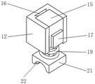
Fig. 9 is a schematic diagram of a first positioning block.
Fig. 10 is a schematic view of the drive mechanism.
FIG. 11 is a schematic view of the second positioning block and the first lug.
FIG. 12 is a cross-sectional view of the second positioning block and the first lug.
Fig. 13 is a schematic view of a spacing mechanism.
Fig. 14 is a schematic sectional view of the stopper mechanism.
Fig. 15 is a perspective schematic view of a winding wheel.
Fig. 16 is a schematic cross-sectional view of a winding wheel.
Number designation in the figures: 1. a vehicle bottom plate; 2. a triangular bracket; 3. a wheel axle; 4. a wheel; 5. a support leg; 6. a shaft; 7. a rear enclosure; 8. a first gear; 9. a friction mechanism; 10. a drive mechanism; 11. a limiting mechanism; 12. a first positioning block; 13. a first guide groove; 14. a trapezoidal limit chute; 15. a guide block; 16. a trapezoidal limiting slide block; 17. a rack; 18. a third return spring; 19. a buffer spring; 20. a telescopic rod; 21. briquetting; 22. an arc-shaped friction plate; 23. a second positioning block; 24. a sliding cavity; 25. a slide hole; 26. a second guide groove; 27. a first lug; 28. a third guide groove; 29. a weight block; 30. a first return spring; 31. a limiting hook; 32. a drive block; 33. a tension spring plate; 34. a second return spring; 35. a drive shaft; 36. a second gear; 37. a third gear; 38. a winding wheel; 39. rotating the hole; 40. a reset ring groove; 41. a wire winding ring groove; 42. a swing rod; 43. a limiting sleeve; 44. a first stopper; 45. a second limiting block; 46. a limiting spring; 47. limiting a swing shaft; 48. a volute spiral spring; 49. a second lug; 50. a movable groove; 51. a brake cable; 52. a brake lever module; 53. a transition block; 54. a vehicle body.
Detailed Description
As shown in fig. 1, it includes a car body 54 composed of a car bottom plate 1, two triangular supports 2, a wheel axle 3, two wheels 4, two support legs 5, two beams 6 and a rear fence 7, and is characterized in that: the brake comprises a first gear 8, a friction mechanism 9, a driving mechanism 10, a limiting mechanism 11 and a brake lever module 52, wherein the first gear 8 is arranged on a wheel shaft 3 as shown in figures 2 and 5; the friction mechanism 9 is fixedly arranged at the lower end of the vehicle bottom plate 1 and is matched with the wheel shaft 3; as shown in fig. 2, 3 and 6, a driving mechanism 10 is fixedly arranged at the lower end of the vehicle bottom plate 1 and is matched with a friction mechanism 9; as shown in fig. 3 and 5, a limiting mechanism 11 is arranged at the lower end of the vehicle bottom plate 1 and is matched with a driving mechanism 10; as shown in fig. 1 and 5, the brake lever module 52 is mounted on the handle of the shaft 6 and connected to the limiting mechanism 11 through the brake cable 51.
As shown in fig. 7, the friction mechanism 9 includes a first positioning block 12, a guide block 15, a trapezoidal limit slider 16, a rack 17, a third return spring 18, a buffer spring 19, an expansion link 20, a pressing block 21, and an arc-shaped friction plate 22, wherein as shown in fig. 2, the first positioning block 12 is fixedly mounted at the lower end of the vehicle bottom plate 1; as shown in fig. 8, the guide block 15 is inserted into the first guide groove 13 of the first positioning block 12 by the sliding fit of the trapezoidal limit sliding block 16 mounted thereon and the trapezoidal limit sliding groove 14 of the first positioning block 12; as shown in fig. 7, a rack 17 is mounted on the side end face of the guide block 15 to be engaged with the drive mechanism 10; as shown in fig. 2 and 7, the third return spring 18 is arranged between the guide block 15 and the vehicle bottom plate 1; as shown in fig. 7, the pressing block 21 is located below the guide block 15 and connected with the lower end of the guide block 15 through the telescopic rod 20; an arc friction plate 22 matched with the wheel shaft 3 is arranged in the arc groove at the lower end of the pressing block 21; the buffer spring 19 is nested on the telescopic rod 20.
As shown in fig. 10, the driving mechanism 10 includes a second positioning block 23, a first support lug 27, a weight 29, a first return spring 30, a limit hook 31, a driving block 32, a second return spring 34, a transmission shaft 35, a second gear 36, and a third gear 37, wherein as shown in fig. 3, the second positioning block 23 having a sliding cavity 24 is fixedly mounted at the lower end of the vehicle bottom plate 1; as shown in fig. 11 and 12, two first lugs 27 having third through-going guide slots 28 are mounted on the lower end of the second positioning block 23; as shown in fig. 3, the driving block 32 is mounted between the two first lugs 27 through a transmission shaft 35, and its upper end enters the sliding cavity 24 through the second guiding groove 26 communicating with the sliding cavity 24 at the lower end of the second positioning block 23, and cooperates with the weight 29 slidably mounted in the sliding cavity 24; the upper end of the driving block 32 has a slope; as shown in fig. 10, the transmission shaft 35 slides up and down along the third guide grooves 28 on the two first lugs 27; a second gear 36 and a third gear 37 are respectively arranged at two ends of the transmission shaft 35; as shown in fig. 6, the third gear 37 is engaged with the rack 17 in the friction mechanism 9; as shown in fig. 2, the second gear 36 is located above and cooperates with the first gear 8; as shown in fig. 3, a second return spring 34 is nested on the drive block 32 to return the motion of the drive block 32; two first return springs 30 are symmetrically arranged in the sliding cavity 24 to return the movement of the weight 29; one end of a limiting hook 31 passes through a sliding hole 25 on the side wall of the second positioning block 23 and transversely communicated with the sliding cavity 24 to be fixedly connected with the weight 29, and one end with the hook is matched with the limiting mechanism 11.
As shown in fig. 13, the limiting mechanism 11 includes a winding wheel 38, a swing link 42, a limiting sleeve 43, a first limiting block 44, a limiting spring 46, a limiting swing shaft 47, and a spiral spring 48, wherein as shown in fig. 1 and 3, the winding wheel 38 is mounted between two second lugs 49 fixedly connected to the lower end of the chassis 1 through the limiting swing shaft 47; as shown in fig. 4 and 14, a spiral spring 48 is nested on the limit swing shaft 47 to reset the rotation of the winding wheel 38; as shown in fig. 13, the position limiting sleeve 43 is connected with the winding wheel 38 through the swing rod 42; as shown in fig. 4 and 14, the first stopper 44 is slidably mounted in the stopper sleeve 43 to cooperate with the hook portion of the stopper hook 31 in the driving mechanism 10; the limiting spring 46 is installed in the limiting sleeve 43 and has a resetting function for the sliding of the first limiting block 44.
As shown in fig. 1 and 5, the end of the brake cable 51 not connected to the lever module 52 is wound around the winding wheel 38.
As shown in fig. 1, the vehicle body further comprises a transition block 53, wherein the transition block 53 is provided with a through round hole, and the transition block 53 is arranged at the lower end of the vehicle bottom plate 1 close to the shaft 6; the brake cable 51 connecting the brake lever module 52 and the limiting mechanism 11 passes through a round hole on a transition block 53 arranged at the lower end of the vehicle bottom plate 1, and the transition block 53 provides a certain fulcrum for the brake cable 51.
As shown in fig. 14, the limiting mechanism 11 further includes two second limiting blocks 45, the two second limiting blocks 45 are symmetrically installed on the first limiting block 44 at one end of the limiting sleeve 43, and limit the sliding of the first limiting block 44; the two second limit blocks 45 and the limit spring 46 work together to prevent the first limit block 44 from sliding out and separating from the limit sleeve 43, so that the limit effect of the first limit block 44 on the limit hook 31 is ensured.
The lower end of the first stopper 44 has an inclined surface, and the inclined surface is matched with the stopper hook 31 in the driving mechanism 10; the slope at the lower end of the first stopper 44 functions to accelerate the return of the stopper hook 31 instantaneously under the action of the two first return springs 30 when the stopper hook 31 in the driving mechanism 10 returns, and when the stopper hook 31 strikes the slope on the first stopper 44, the stopper hook 31 forces the first stopper 44 to compress the stopper spring 46 and retract into the stopper sleeve 43, and when the hook portion of the stopper hook 31 passes over the first stopper 44, the slope returns under the action of the stopper spring 46 and re-forms a stopper for the stopper hook 31.
As shown in fig. 15 and 16, a through rotating hole 39 is formed between two end surfaces of the winding wheel 38 in the limiting mechanism 11, a return ring groove 40 is formed on an inner wall of the rotating hole 39 along the circumferential direction, and a winding ring groove is formed on an outer circumferential surface of the winding wheel 38 along the circumferential direction.
As shown in fig. 5, one end of the brake cable 51 connected with the limiting mechanism 11 is wound in the winding ring groove; as shown in fig. 14, the spiral spring 48 is located in the return chute, and one end of the spiral spring is fixedly connected with the limit swing shaft 47, and the other end of the spiral spring is fixedly connected with the inner wall of the return ring groove 40.
As shown in fig. 1, the axle 3 of the vehicle body 54 is in bearing fit with the two triangular brackets 2, the first gear 8 is in key fit with the axle 3, and the two wheels 4 are respectively and fixedly mounted at two ends of the axle 3; as shown in fig. 3, the lower end surface of the vehicle bottom plate 1 in the vehicle body 54 is provided with a movable groove 50, the movable groove 50 is located above the position-limiting sleeve 43 and is matched with the position-limiting sleeve, and the movable groove 50 provides a movable space for the position-limiting sleeve 43 to swing upwards around the position-limiting swing shaft 47; the rotation of the wheel 4 can drive the first gear 8 arranged on the wheel shaft 3 to rotate synchronously through the wheel shaft 3.
As shown in fig. 10, the driving mechanism 10 further includes a tension spring plate 33, and the tension spring plate 33 is nested and fixed on the driving block 32; the lower end of the second return spring 34 is connected with the tension spring plate 33, and the upper end of the second return spring is connected with the lower end of the second positioning block 23; the tension spring plate 33 stretches the second return spring 34 when the driving block 32 moves downward, and the stretched second return spring 34 exerts a return action on the movement of the driving block 32.
As shown in fig. 10, the driving mechanism 10 has a shaft hole at the lower end of the driving block 32, and the shaft hole at the lower end of the driving block 32 is in bearing fit with the transmission shaft 35.
As shown in fig. 8 and 9, the first guide groove 13 is opened on the side end surface of the first positioning block 12, and the first guide groove 13 penetrates the upper and lower end surfaces of the first positioning block 12; the trapezoidal limiting sliding groove 14 is positioned on the side wall of the first guide groove 13 and plays a role in positioning and guiding the movement of the guide block 15.
As shown in fig. 2, 3 and 6, the first return spring 30, the second return spring 34 and the third return spring 18 are all extension springs, wherein one end of the first return spring 30 is installed on the side surface of the sliding cavity 24, and the other end is fixedly connected with the weight 29; as shown in fig. 7 and 14, the limiting spring 46 and the buffer spring 19 are both compression springs, wherein one end of the limiting spring 46 is fixedly connected with the first limiting block 44, and the other end is fixedly connected with the inner wall of the limiting sleeve 43; one end of the buffer spring 19 is mounted on the bottom end of the guide block 15, and the other end is mounted on the pressing block 21.
As shown in fig. 3 and 12, the sliding cavity 24 of the second positioning block 23 is coated with grease to ensure that the sliding resistance of the weight 29 installed in the sliding cavity 24 is as close to zero as possible.
The lever module 52 of the present invention is prior art.
The third gear 37 of the invention is just separated from the rack 17 when the friction plate and the wheel shaft 3 generate friction, the guide block 15 can not reset in the braking process under the combined action of the third reset spring 18 and the third gear 37, and the guide block 15 drives the arc-shaped friction plate 22 to always contact and rub with the wheel shaft 3 through the buffer spring 19 and the pressing block 21.
The working process of the invention is as follows: when the speed needs to be reduced when the vehicle descends a slope, the brake cable 51 is pulled through the brake lever in the brake lever module 52 on the handle bar of the shaft 6, the brake cable 51 drives the winding wheel 38 to rotate, the winding wheel 38 drives the scroll spring 48 to deform, and the winding wheel 38 drives the first limit block 44 to separate from the limit hook 31 through the swing rod 42 and the limit sleeve 43 and releases the limit on the limit hook 31; after the limit mechanism 11 releases the limit on the driving mechanism 10, the brake lever in the brake lever module 52 is released, under the reset action of the spiral spring 48, the winding wheel 38 winds a part of the brake cable 51 pulled by the brake lever module 52 on the brake lever module again, and the brake cable 51 drives the brake lever in the brake lever module 52 to swing back to the initial state; then, the weight 29 inclined together with the vehicle body 54 slides to the other side of the sliding cavity 24 under the action of its own weight, the weight 29 presses the inclined surface of the upper end of the driving block 32 and presses the driving block 32, the second gear 36 and the third gear 37 are driven to move downwards along the third guide groove 28 on the first lug 27 through the transmission shaft 35, and simultaneously, the two first return springs 30 are stretched, and the second return spring 34 is stretched; under the mutual meshing action of the rack 17 and the third gear 37, the third gear 37 drives the second gear 36 to idle through the transmission shaft 35, and the rotation direction of the second gear 36 is opposite to that of the first gear 8 in the state; when the second gear 36 meets and meshes with the first gear 8 below, the first gear 8 rotating synchronously with the wheel 4 can instantaneously drive the second gear 36 to rotate reversely because the torque provided by the first gear 8 to the second gear 36 is large, and the second gear 36 drives the third gear 37 to rotate reversely and synchronously through the transmission shaft 35; the third gear 37 drives the guide block 15 to move downwards along the trapezoidal limiting sliding groove 14 through the rack 17, and the third return spring 18 is stretched; when the upper end of the rack 17 is meshed with the third gear 37 and the last tooth at the upper end of the rack 17 is continuously stirred downwards to keep the rack 17 in a downward-pressing state and not move any more, the guide block 15 drives the arc-shaped friction plate 22 to be in contact with the wheel shaft 3 through the buffer spring 19 and the pressing block 21 and generate friction, the buffer spring 19 is compressed and provides enough pressing force for the pressing block 21, so that the speed reduction in the downhill process is realized, and the safety of a puller and a brick transfer device are ensured not to be damaged; in the whole braking process, the puller only acts on the brake crank module 52 to release the hand at once, and in the whole downhill process, the brick transfer device automatically brakes the brick transfer device, so that the physical strength of the puller is greatly saved.
When the fully loaded vehicle body 54 slowly travels down the slope, the vehicle body 54 returns to the horizontal position, and the weight 29 is accelerated toward the initial position along the slide chamber 24 by the two first return springs 30; when the speed of the weight 29 returning to the initial position reaches the maximum, the weight 29 drives the limit hook 31 to impact the inclined surface at the lower end of the first limit block 44; the impact force applied to the lower end slope of the first limit block 44 causes the first limit block 44 to contract into the telescopic sleeve and compress the limit spring 46; the limit spring 46 does not limit the reset of the limit hook 31; when the limit hook 31 crosses the first limit block 44, the first limit block 44 moves outwards from the telescopic sleeve under the action of the limit spring 46 and limits the limit hook 31 again, before the brake crank module 52 is pressed down again, the first limit block 44 always limits the limit hook 31, so that the movement of the driving mechanism 10 is limited, and the vehicle body 54 does not generate an automatic speed reduction effect; when the weight 29 is separated from the driving block 32, the driving block 32 drives the second gear 36 to be separated from the first gear 8 through the transmission shaft 35 under the action of the second return spring 34, and the third gear 37 drives the second gear 36 to reversely idle and return to the initial position through the transmission shaft 35 under the action of the rack 17; under the action of the third return spring 18, the guide block 15 returns to the initial position along the first guide groove 13, and the brick-pulling vehicle is decelerated.
In conclusion, the invention has the beneficial effects that: when the vehicle body 54 decelerates downhill, the automatic deceleration function of the vehicle body 54 can be realized only by acting the brake crank module 52, and the brake crank module 52 is not required to be held all the time in the deceleration process like the traditional manual brake device, so that the physical strength of a puller is saved to the maximum extent, the working efficiency is improved, the safety factor of the fully loaded vehicle body 54 in the downhill process is improved, the safety of the puller is further ensured, the occurrence of collision accidents caused by the fact that the vehicle body 54 does not decelerate is avoided, the possibility of accidents is fundamentally reduced, and the life safety of individuals is ensured.
Claims (5)
1. The utility model provides a fragment of brick transportation equipment for building field, it includes the automobile body of compriseing vehicle bottom plate, two A-frame supports, shaft, two wheels, two stabilizer blades, two thills and back fender, its characterized in that: the brake comprises a first gear, a friction mechanism, a driving mechanism, a limiting mechanism and a brake crank module, wherein the first gear is arranged on a wheel shaft; the friction mechanism is fixedly arranged at the lower end of the vehicle bottom plate and is matched with the wheel shaft; the driving mechanism is fixedly arranged at the lower end of the vehicle bottom plate and is matched with the friction mechanism; the limiting mechanism is arranged at the lower end of the vehicle bottom plate and is matched with the driving mechanism; the brake crank module is arranged at the shaft handle and is connected with the limiting mechanism through a brake cable;
the friction mechanism comprises a first positioning block, a guide block, a trapezoidal limiting slide block, a rack, a third return spring, a buffer spring, a telescopic rod, a pressing block and an arc-shaped friction plate, wherein the first positioning block is fixedly arranged at the lower end of the vehicle bottom plate, and the guide block is embedded into a first guide groove on the first positioning block through the sliding fit of the trapezoidal limiting slide block arranged on the guide block and a trapezoidal limiting slide groove on the first positioning block; the rack is arranged on the side end face of the guide block and is matched with the driving mechanism; the third return spring is arranged between the guide block and the vehicle bottom plate; the pressing block is positioned below the guide block and is connected with the lower end of the guide block through a telescopic rod; an arc friction plate matched with the wheel shaft is arranged in the arc groove at the lower end of the pressing block; the buffer spring is nested on the telescopic rod;
the driving mechanism comprises a second positioning block, a first support lug, a weight block, a first return spring, a limiting hook, a driving block, a second return spring, a transmission shaft, a second gear and a third gear, wherein the second positioning block with a sliding cavity is fixedly arranged at the lower end of the vehicle bottom plate; two first lugs provided with a through third guide groove are arranged at the lower end of the second positioning block; the driving block is arranged between the two first lugs through a transmission shaft, and the upper end of the driving block enters the sliding cavity through a second guide groove communicated with the sliding cavity at the lower end of the second positioning block and is matched with the weight block arranged in the sliding cavity in a sliding way; the upper end of the driving block is provided with an inclined plane; the transmission shaft slides up and down along the third guide grooves on the two first lugs; a second gear and a third gear are respectively arranged at two ends of the transmission shaft; the third gear is meshed with a rack in the friction mechanism; the second gear is positioned above and matched with the first gear; the second return spring is nested on the driving block to return the motion of the driving block; the two first return springs are symmetrically arranged in the sliding cavity to return the movement of the weight block; one end of the limiting hook penetrates through a sliding hole which is formed in the side wall of the second positioning block and is transversely communicated with the sliding cavity to be fixedly connected with the weight block, and one end with the hook is matched with the limiting mechanism;
the limiting mechanism comprises a winding wheel, a swing rod, a limiting sleeve, a first limiting block, a limiting spring, a limiting swing shaft and a volute spiral spring, wherein the winding wheel is arranged between two second lugs fixedly connected with the lower end of the vehicle bottom plate through the limiting swing shaft, and the volute spiral spring is nested on the limiting swing shaft to reset the rotation of the winding wheel; the limiting sleeve is connected with the winding wheel through the oscillating bar; the first limiting block is slidably arranged in the limiting sleeve and matched with the hook part of the limiting hook in the driving mechanism; the limiting spring is arranged in the limiting sleeve and has a reset function on the sliding of the first limiting block;
one end of the brake cable, which is not connected with the brake handle module, is wound on the winding wheel;
the driving mechanism also comprises a tension spring plate which is fixed on the driving block in an embedded manner; the lower end of the second return spring is connected with the tension spring plate, and the upper end of the second return spring is connected with the lower end of the second positioning block;
the lower end of a driving block in the driving mechanism is provided with a shaft hole, and the shaft hole at the lower end of the driving block is matched with a transmission shaft through a bearing;
the first guide groove is formed on the side end face of the first positioning block and is communicated with the upper end face and the lower end face of the first positioning block; the trapezoidal limiting sliding groove is positioned on the side wall of the first guide groove and plays a role in positioning and guiding the motion of the guide block;
the first return spring, the second return spring and the third return spring are all extension springs, wherein one end of the first return spring is installed on the side surface of the sliding cavity, and the other end of the first return spring is fixedly connected with the weight block; the limiting spring and the buffer spring are both compression springs, wherein one end of the limiting spring is fixedly connected with the first limiting block, and the other end of the limiting spring is fixedly connected with the inner wall of the limiting sleeve; one end of the buffer spring is arranged at the bottom end of the guide block, and the other end of the buffer spring is arranged on the pressing block;
and lubricating grease is smeared in the sliding cavity of the second positioning block.
2. Brick transfer equipment for the construction field according to claim 1, characterized in that: the transition block is provided with a through round hole and is arranged at the lower end of the vehicle bottom plate close to the beam; the brake cable connecting the brake crank module and the limiting mechanism penetrates through a round hole in a transition block arranged at the lower end of the vehicle bottom plate.
3. Brick transfer equipment for the construction field according to claim 1, characterized in that: the limiting mechanism further comprises two second limiting blocks, and the two second limiting blocks are symmetrically arranged on one end, positioned in the limiting sleeve, of the first limiting block and used for limiting the sliding of the first limiting block;
the lower end of the first limiting block is provided with an inclined plane, and the inclined plane is matched with a limiting hook in the driving mechanism.
4. Brick transfer equipment for the construction field according to claim 3, characterized in that: a through rotating hole is formed between two end faces of a winding wheel in the limiting mechanism, a reset ring groove is formed in the inner wall of the rotating hole along the circumferential direction, and a winding ring groove is formed in the outer circular surface of the winding wheel along the circumferential direction;
one end of the brake cable connected with the limiting mechanism is wound in the winding ring groove; the volute spiral spring is positioned in the reset sliding groove, one end of the volute spiral spring is fixedly connected with the limiting swing shaft, and the other end of the volute spiral spring is fixedly connected with the inner wall of the reset ring groove.
5. Brick transfer equipment for the construction field according to claim 1, characterized in that: the wheel shaft in the vehicle body is matched with the two triangular supports through a bearing, the first gear is matched with the wheel shaft through a key, and the two wheels are respectively and fixedly arranged at two ends of the wheel shaft; the lower end surface of the vehicle bottom plate in the vehicle body is provided with a movable groove which is positioned above the limiting sleeve and matched with the limiting sleeve.
Priority Applications (1)
| Application Number | Priority Date | Filing Date | Title |
|---|---|---|---|
| CN202110211109.XA CN112874591A (en) | 2018-12-29 | 2018-12-29 | Brick transfer equipment used in building field |
Applications Claiming Priority (2)
| Application Number | Priority Date | Filing Date | Title |
|---|---|---|---|
| CN202110211109.XA CN112874591A (en) | 2018-12-29 | 2018-12-29 | Brick transfer equipment used in building field |
| CN201811635712.5A CN109552389B (en) | 2018-12-29 | 2018-12-29 | Fragment of brick transfer device that building field used |
Related Parent Applications (1)
| Application Number | Title | Priority Date | Filing Date |
|---|---|---|---|
| CN201811635712.5A Division CN109552389B (en) | 2018-12-29 | 2018-12-29 | Fragment of brick transfer device that building field used |
Publications (1)
| Publication Number | Publication Date |
|---|---|
| CN112874591A true CN112874591A (en) | 2021-06-01 |
Family
ID=65871946
Family Applications (3)
| Application Number | Title | Priority Date | Filing Date |
|---|---|---|---|
| CN202110211109.XA Withdrawn CN112874591A (en) | 2018-12-29 | 2018-12-29 | Brick transfer equipment used in building field |
| CN202110211105.1A Withdrawn CN112874613A (en) | 2018-12-29 | 2018-12-29 | Fragment of brick transportation equipment that building engineering field was used |
| CN201811635712.5A Active CN109552389B (en) | 2018-12-29 | 2018-12-29 | Fragment of brick transfer device that building field used |
Family Applications After (2)
| Application Number | Title | Priority Date | Filing Date |
|---|---|---|---|
| CN202110211105.1A Withdrawn CN112874613A (en) | 2018-12-29 | 2018-12-29 | Fragment of brick transportation equipment that building engineering field was used |
| CN201811635712.5A Active CN109552389B (en) | 2018-12-29 | 2018-12-29 | Fragment of brick transfer device that building field used |
Country Status (1)
| Country | Link |
|---|---|
| CN (3) | CN112874591A (en) |
Cited By (3)
| Publication number | Priority date | Publication date | Assignee | Title |
|---|---|---|---|---|
| CN113911200A (en) * | 2021-11-03 | 2022-01-11 | 中铁建电气化局集团第四工程有限公司 | Multifunctional hand-held pushing and hand-loosening braking track small flat car |
| CN114112493A (en) * | 2021-11-16 | 2022-03-01 | 山西交控生态环境股份有限公司 | A portable sampling device for soil investigation |
| CN114934678A (en) * | 2022-04-06 | 2022-08-23 | 广州协安建设工程有限公司 | Integral type consigning, sliding and installing construction method for full-glass curtain wall |
Families Citing this family (2)
| Publication number | Priority date | Publication date | Assignee | Title |
|---|---|---|---|---|
| CN113772487B (en) * | 2021-07-26 | 2023-04-07 | 厦门市恒亿建安材料有限公司 | Hand-push pipe winding vehicle |
| CN113701002B (en) * | 2021-10-19 | 2023-01-31 | 安徽省大气探测技术保障中心 | Adjustable bracket for meteorological observation instrument |
Family Cites Families (6)
| Publication number | Priority date | Publication date | Assignee | Title |
|---|---|---|---|---|
| US9108657B2 (en) * | 2012-05-16 | 2015-08-18 | Cooper Technologies Company | Cart braking system |
| CH708357B1 (en) * | 2013-07-18 | 2017-11-15 | Sbb Ag Recht & Compliance | Dolly. |
| US9333979B2 (en) * | 2014-02-13 | 2016-05-10 | Avi Iron Solutions Ltd. | Auxiliary pusher device |
| CN205828074U (en) * | 2016-07-28 | 2016-12-21 | 江西明正变电设备有限公司 | Roller installed by a kind of transformator |
| CN108423056A (en) * | 2018-05-11 | 2018-08-21 | 清远凤亿宝电子商务有限公司 | A kind of logistics e-commerce trolley |
| CN208291306U (en) * | 2018-05-23 | 2018-12-28 | 刘灿敏 | A kind of hydraulic engineering cart |
-
2018
- 2018-12-29 CN CN202110211109.XA patent/CN112874591A/en not_active Withdrawn
- 2018-12-29 CN CN202110211105.1A patent/CN112874613A/en not_active Withdrawn
- 2018-12-29 CN CN201811635712.5A patent/CN109552389B/en active Active
Cited By (3)
| Publication number | Priority date | Publication date | Assignee | Title |
|---|---|---|---|---|
| CN113911200A (en) * | 2021-11-03 | 2022-01-11 | 中铁建电气化局集团第四工程有限公司 | Multifunctional hand-held pushing and hand-loosening braking track small flat car |
| CN114112493A (en) * | 2021-11-16 | 2022-03-01 | 山西交控生态环境股份有限公司 | A portable sampling device for soil investigation |
| CN114934678A (en) * | 2022-04-06 | 2022-08-23 | 广州协安建设工程有限公司 | Integral type consigning, sliding and installing construction method for full-glass curtain wall |
Also Published As
| Publication number | Publication date |
|---|---|
| CN112874613A (en) | 2021-06-01 |
| CN109552389B (en) | 2021-03-26 |
| CN109552389A (en) | 2019-04-02 |
Similar Documents
| Publication | Publication Date | Title |
|---|---|---|
| CN109552389B (en) | Fragment of brick transfer device that building field used | |
| CN109677478B (en) | Building brick transfer device | |
| CN101759076B (en) | Elevator buffer | |
| CN101862512B (en) | Adjustable high-rise escape device | |
| CN204873326U (en) | Elevator overspeed governor | |
| CN201703934U (en) | Centrifugal fling block type speed-limiting anti-falling safety device | |
| CN103523632A (en) | Bidirectional machine-room-free automatic anti-running vehicle speed limiter of single brake pressing-plate device | |
| CN107720544B (en) | A kind of electric block lifting buffer unit | |
| CN201071239Y (en) | Person-carried dragging type elevator for construction | |
| CN108394493B (en) | Vertical telescopic bicycle parking device | |
| CN201334345Y (en) | Lifting mechanism of hand-operated aerial operation hanging basket | |
| CN215084426U (en) | High altitude construction protection device for construction | |
| CN203558668U (en) | Two-way machine-room-less automatic anti-slip speed limiter with single brake pressure plate device | |
| CN106629312B (en) | Wirerope key-operated brake | |
| CN204873321U (en) | Device for preventing elevator car is unexpected to be removed | |
| CN206126543U (en) | Novel automatically, prevent one -way automatic re -setting overspeed governor of swift current car | |
| CN201539241U (en) | Multifunctional emergency brake attached to balancing weight | |
| CN111622039A (en) | Mountain coiling highway protection rail equipment | |
| CN103508290A (en) | Automatic one-way anti-vehicle slip speed limiter without machine room | |
| CN203558665U (en) | Bidirectional machine-room-less automatic anti-slip speed limiter | |
| CN219857132U (en) | Inclined shaft overhead manned device | |
| CN2455677Y (en) | Anti-dropping safety device for elevator and lift apparatus with T-shaped guide railing | |
| CN217676255U (en) | Toe guard of elevator car | |
| CN216153759U (en) | Brake pedal capable of being reset reliably | |
| CN212766180U (en) | Automobile and wheel-side parking brake device thereof |
Legal Events
| Date | Code | Title | Description |
|---|---|---|---|
| PB01 | Publication | ||
| PB01 | Publication | ||
| SE01 | Entry into force of request for substantive examination | ||
| SE01 | Entry into force of request for substantive examination | ||
| WW01 | Invention patent application withdrawn after publication | ||
| WW01 | Invention patent application withdrawn after publication |
Application publication date: 20210601 |