Adjustable injection urea can get rid of waste heat stove of flying dust
Technical Field
The invention relates to the technical field of garbage treatment machinery, in particular to a waste heat furnace capable of removing fly ash by adjusting sprayed urea.
Background
Because the hazardous waste contains nitrogen elements, and the specification requires that the combustion temperature of the secondary combustion chamber stays at 1100 ℃ for not less than 2 seconds, the nitrogen elements in the waste and the nitrogen in the combustion air can generate nitrogen oxides in the high-temperature combustion process, and the specification has the emission limit requirement on the emission value of the nitrogen oxides and can not exceed the standard. For this reason, it is necessary to inject a urea solution near the inlet position of the boiler (flue gas temperature is 950 ℃), and the injected urea solution reacts with nitrogen oxides in the flue gas to reduce the nitrogen oxides into nitrogen and water and to be discharged as components of the flue gas, and this process of removing the nitrogen oxides is called SNCR process. The process has a great relationship between the removal effect and removal efficiency of nitrogen oxides and the temperature range of flue gas, but the set reaction temperature range has a great relationship with the heat value, treatment capacity and the like of incinerated materials, and the temperature range changes constantly. In order to meet the requirement of temperature change, two layers of SNCR urea spray guns are generally arranged in the interval so as to adjust the urea spraying position according to the position temperature and improve the reaction efficiency. Even so, the temperature of the urea injection position cannot be accurately adapted, causing fluctuation in removal efficiency, thereby causing an increase in the urea injection amount and increasing the running cost.
The hazardous waste incineration waste heat boiler is usually in a full-film type wall form, the film type wall is in a structure that pipes are directly connected into a piece by flat iron, and the surrounding film type walls are connected to form a cavity of a circulating flue. When the flue gas flows through diaphragm type wall cavity, the dust in the flue gas can amass on the surface of diaphragm type wall, thickens gradually along with the sedimentary flying ash of increase of operating duration, and the heat transfer effect of the pipe that can greatly reduced reduces the heat exchange efficiency of boiler, and boiler exhaust gas temperature increases, causes thermal waste, and boiler steam output descends simultaneously, reduces the benefit of enterprise. The general deashing mode has rapping deashing, shock wave deashing two kinds of modes, and diaphragm type wall boiler structure is very firm, and it has not obvious effect to rap the deashing, and the shock wave deashing is because the volume of cavity is great, and deashing efficiency is also very limited, and dangerous waste incineration's flue gas viscidity is great in addition, and the fly ash has certain viscidity, has more increased the degree of difficulty of deashing, and dangerous waste incineration boiler deposition is difficult to the clearance problem that ubiquitous.
Disclosure of Invention
The invention aims to provide a waste heat furnace capable of removing fly ash by adjusting sprayed urea so as to solve the problems in the prior art.
In order to solve the technical problems, the invention provides the following technical scheme: the utility model provides an adjustable injection urea can get rid of waste heat stove of flying dust, includes the waste heat stove body, its characterized in that: the waste heat furnace body comprises a plurality of boiler membrane type wall pipes and boiler membrane type wall fins positioned between two adjacent boiler membrane type wall pipes, the boiler membrane type wall fins are provided with openings, the outer side of the waste heat furnace body is provided with a double-fluid spray gun, one end of the double-fluid spray gun close to a spray head penetrates through the openings, a compressed air atomization pipeline and a urea solution pipeline are arranged in the double-fluid spray gun, the compressed air atomization pipeline and the urea solution pipeline are mutually communicated, a plurality of temperature measuring points are arranged in the waste heat furnace body, the double-fluid spray gun moves according to the temperature of the temperature measuring points, the temperature measuring points are arranged on one side in the boiler membrane type wall pipes, and evenly distributed be in on the boiler diaphragm type wall pipe, open-ended both sides are provided with first supporting seat, and first supporting seat sets up in the outer wall of boiler diaphragm type wall fin, are provided with the mount pad on the two-fluid spray gun, and the mount pad passes through first connecting rod and first supporting seat sliding connection.
According to the technical scheme, the film type wall fins of the boiler are provided with the openings, so that the spray heads on the double-fluid spray gun penetrate through the openings and extend into the inner cylinder of the waste heat furnace, the double-fluid spray gun is internally provided with the compressed air atomization pipeline and the urea solution pipeline, when the compressed air and the urea solution are respectively introduced into the compressed air atomization pipeline and the urea solution pipeline, the two pipelines are communicated with each other, so that the spray heads in the double-fluid spray gun spray the atomization effect of the urea solution, and the urea solution is prevented from being evaporated to dryness by high-temperature flue gas; the waste heat furnace body is internally provided with a plurality of temperature measuring points, the spray head spraying position of the double-fluid spray gun is adjusted according to the position temperature of the temperature measuring points, the reaction efficiency is improved, the redundant urea spraying quantity is avoided, the operation cost is reduced, the temperature measuring points are arranged on one side in the boiler membrane type wall pipe near the opening, the boiler membrane type wall pipe is distributed with a plurality of temperature measuring points from top to bottom, the temperature value detected by the temperature measuring points is fed back to the PLC control system, the position of the double-fluid spray gun is positioned by the PLC control system, so that the urea spraying time and the reaction interval of the double-fluid spray gun are accurately controlled, the double-fluid spray gun is provided with a mounting seat, the double-fluid spray gun can horizontally move in the mounting seat, when the spraying furnace is finished, the double-fluid spray gun can move out of the waste heat furnace body in the mounting seat, so that the spray head moves out of the openings of the boiler membrane type wall fins, and the high-temperature smoke in the furnace is prevented from damaging the double-fluid spray gun, the service life of the invention is prolonged; the two sides of the opening are provided with first supporting seats, the first supporting seats are arranged on the outer wall of a boiler membrane wall fin, the first supporting seats are in a shape like a Chinese character 'ao', the rod bodies of the first connecting rods are attached to the grooves of the first supporting seats, so that the first connecting rods can slide up and down in the first supporting seats, the two sides of the mounting seats are fixedly connected with the two first connecting rods, the two fluid spray guns on the mounting seats can be driven by the first connecting rods to move up and down in the boiler to spray, the two fluid spray guns can be matched with temperature measuring points to adjust the spraying positions of the two fluid spray guns, and the pin removal reaction efficiency is improved.
Preferably, the first connecting rod is Z-shaped.
According to the technical scheme, the first connecting rod is Z-shaped, and as the first connecting rod is the mounting seat fixedly connected with one end, the other end is buckled in the groove of the first supporting seat and can slide, the structure of the Z-shaped connecting rod is relatively stable, and the mounting seat and the spray gun are driven by the first connecting rod to slide more stably in the groove of the first supporting seat.
Preferably, a sealing chamber is formed among the first connecting rod, the mounting seat and the boiler membrane wall fin, and the sealing chamber is communicated with the waste heat furnace body.
According to the technical scheme, the sealing chamber is formed among the first connecting rod, the mounting seat and the boiler membrane type wall fins and is communicated with the interior of the waste heat furnace body, when the double-fluid spray gun sprays urea into the waste heat furnace body, the sprayed urea solution reacts with nitrogen oxide in smoke, the nitrogen oxide is reduced into nitrogen and water, the sealing chamber can protect the smoke in the boiler and the sprayed mist urea from overflowing from the opening of the boiler membrane type wall fins, the reduction of reaction efficiency caused by insufficient reactants in the boiler is avoided, and the increase of the cost of denitration is avoided.
Preferably, the sealed chamber is provided with a cooling compressed air pipeline.
According to the technical scheme, the cooling air is introduced into the sealing chamber through the cooling compressed air pipeline, so that not only can the smoke in the boiler be prevented from escaping, but also the double-fluid spray gun is cooled, the high-temperature smoke in the waste heat furnace is prevented from damaging the double-fluid spray gun, and the service life of the double-fluid spray gun is prolonged.
Preferably, one side is equipped with the fly ash remove device in the waste heat furnace body, and the fly ash remove device includes compressed air jetting pipe, installs a plurality of compressed air jetting shower nozzle on the compressed air jetting pipe, and the compressed air incoming end is installed to compressed air jetting pipe one side, and the compressed air incoming end other end extends outside waste heat furnace body top end wall.
According to the technical scheme, one side is equipped with flying dust remove device in the waste heat furnace body, flying dust remove device includes compressed air jetting pipe, install a plurality of compressed air jetting shower nozzle on the compressed air jetting pipe, the compressed air incoming end is installed to compressed air jetting pipe one side, the compressed air incoming end other end extends outside waste heat furnace body top wall, put compressed air into the compressed air incoming end, thereby make compressed air circulate to compressed air jetting pipe, blow towards boiler membrane type wall pipe through every nozzle, thereby clear away the sedimentary flying dust on this internal boiler membrane type wall pipe of waste heat furnace and the boiler membrane type wall fin.
Preferably, the compressed air inlet end is provided with a flow controller.
According to the technical scheme, according to the ash deposition condition in the furnace, through controlling the flow controller on the compressed air inlet end, a worker can control the flow and the pressure of the compressed air in the compressed air injection pipe according to the ash deposition condition in the waste heat furnace body, so that the injection force of the compressed air injection nozzle can be enhanced or weakened, and the phenomenon that the boiler membrane wall pipe is abraded due to overlarge cleaning pressure of the compressed air injection pipe is avoided.
Preferably, the two ends of the compressed air injection pipe are provided with second connecting rods, the two second connecting rods are connected with second supporting seats, and the top ends and the bottom ends of the two second supporting seats are connected to the top and the bottom of the waste heat furnace body.
According to the technical scheme, the top ends and the bottom ends of the two second supporting seats are connected to the top and the bottom of the waste heat furnace body, the two second connecting rods are correspondingly arranged in the grooves in the two second supporting seats and can move up and down, the compressed air injection pipe is fixedly connected between the two second connecting rods and can move up and down according to the position of the fly ash to be cleaned in the furnace, and the cleaning effect of removing the fly ash is further improved;
preferably, the two ends of the first supporting seat and the two ends of the second supporting seat are both provided with limiting blocks.
According to the technical scheme, the limiting blocks are embedded in the grooves at the tops and the bottoms of the first supporting seat and the second supporting seat, when the PLC control system controls the mounting seat to move up and down, the first connecting rod fixedly connected with the mounting seat slides up and down in the groove of the first supporting seat, and the first connecting rod is prevented from slipping out of the first supporting seat through the limiting blocks in a sliding mode, so that the process that the double-fluid spray gun drops on the floor in the furnace to spray urea is stopped, and further, the waste of the company cost is avoided; the two ends of the compression vacancy injection pipe are connected with second connecting rods, the two second connecting rods are respectively connected with two second supporting seats, and the compressed air injection pipe can move up and down according to the position of the clean fly ash through the second connecting rods and the second supporting seats, so that the fly ash removal cleaning effect is further improved; the flow and pressure of the compressed air in the compressed air injection pipe can be controlled by a worker according to the dust deposition condition in the furnace by controlling the flow controller on the compressed air inlet end, so that the injection force of the compressed air injection nozzle can be enhanced or weakened.
Compared with the prior art, the invention has the beneficial effects that:
1. the invention is provided with a set of complete PLC control system, a plurality of temperature measuring points are arranged in the up-down moving area of a urea spray gun, the spray gun can be ensured to move to the position of a set temperature value in real time through a first supporting seat, a first connecting rod and a mounting seat according to the temperature measuring points, the temperature interval of urea injection can be accurately controlled, and the efficient denitration effect is ensured; by the design of the movable urea spray gun, the urea spraying and denitration reaction interval can be accurately controlled, the denitration efficiency is improved, the use amount of urea is reduced, the operation cost is reduced, and the enterprise efficiency is improved; establish the seal chamber in the middle of spray gun and spout, spray gun and seal chamber can reciprocate along first supporting seat, lets in cooling air toward the seal chamber, not only can avoid the flue gas in the boiler to escape outward, still plays refrigerated effect to the double-fluid spray gun, avoids the high temperature flue gas in the waste heat stove to damage the double-fluid spray gun, has prolonged the life of double-fluid spray gun.
2. The fly ash removing device is arranged on one side in the waste heat furnace body and comprises a compressed air injection pipe, a plurality of compressed air injection nozzles are mounted on the compressed air injection pipe, a compressed air inlet end is mounted on one side of the compressed air injection pipe, the other end of the compressed air inlet end extends out of the waste heat furnace body, compressed air is placed into the compressed air inlet end, accordingly, the compressed air is circulated to the compressed air injection pipe, and is injected towards the film-type wall pipe of the boiler through each nozzle, so that fly ash deposited on the film-type wall pipe and the film-type wall fins in the waste heat furnace body is removed, a worker moves the compressed air injection pipe along the film-type wall in the vertical direction through a second connecting rod and a second supporting seat according to the position of the fly ash, and the fly ash removing effect is better; according to the condition of dust deposition in the boiler, the flow and pressure of the compressed air in the compressed air injection pipe can be controlled by controlling the flow controller on the inlet end of the compressed air, so that the surface of the membrane wall of the boiler is ensured to be clean, the efficiency of the boiler is ensured, the steam yield of the boiler is ensured, and the operation benefit is ensured. The accumulated dust on the surface of the membrane type wall is cleaned on line in real time, the heat exchange efficiency of the boiler is ensured, the steam generation amount is ensured, the heat utilization rate is improved, and the enterprise income is ensured.
Drawings
The accompanying drawings, which are included to provide a further understanding of the invention and are incorporated in and constitute a part of this specification, illustrate embodiments of the invention and together with the description serve to explain the principles of the invention and not to limit the invention.
In the drawings:
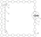
FIG. 1 is a top view of the structure of the present invention;
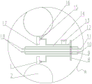
FIG. 2 is an enlarged view of the invention at A;
FIG. 3 is a schematic view of the structure of the compressed air blowing pipe of the present invention;
FIG. 4 is a schematic view of the temperature measuring point of the present invention;
reference numbers in the figures: 1. boiler membrane type wall fins; 2. a boiler membrane wall tube; 3. a second support seat; 4. a second connecting rod; 5. a compressed air blowing pipe; 6. a compressed air blowing nozzle; 7. a compressed air inlet end; 8. a mounting seat; 9. a two-fluid spray gun; 10. a urea solution conduit; 11. a compressed air atomization conduit; 12. a first connecting rod; 13. cooling the compressed air duct; 14. a sealed chamber; 15. a limiting block; 16. a first support base; 17. an opening; 18. a spray head; 19. measuring temperature points; 20. a waste heat furnace body.
Detailed Description
The technical solutions in the embodiments of the present invention will be clearly and completely described below with reference to the drawings in the embodiments of the present invention, and it is obvious that the described embodiments are only a part of the embodiments of the present invention, and not all of the embodiments. All other embodiments, which can be derived by a person skilled in the art from the embodiments given herein without making any creative effort, shall fall within the protection scope of the present invention.
Referring to fig. 1-4, the present invention provides the following technical solutions: referring to fig. 1 and 2, a waste heat furnace capable of adjustably spraying urea and removing fly ash comprises a waste heat furnace body 20, wherein the waste heat furnace body 20 comprises a plurality of boiler membrane wall tubes 2 and boiler membrane wall fins 1 located between two adjacent boiler membrane wall tubes 2, an opening 17 is arranged on each boiler membrane wall fin 1, a two-fluid spray gun 9 is arranged outside the waste heat furnace body 20, one end of each two-fluid spray gun 9 close to a spray head 18 penetrates through the opening 17, a compressed air atomization pipeline 11 and a urea solution pipeline 10 are arranged in each two-fluid spray gun 9, when the compressed air and the urea solution are respectively introduced into the compressed air atomization pipeline 11 and the urea solution pipeline 10, because the two pipelines are communicated with each other, the spray head 18 in the double-fluid spray gun 9 sprays the atomization effect of the urea solution, and the urea solution is prevented from being evaporated to dryness by high-temperature flue gas in the inner cylinder of the waste heat furnace body 20; a plurality of temperature measuring points 19 are arranged in the waste heat furnace body 20, the spraying position of the spray head 18 of the double-fluid spray gun 9 is adjusted according to the position temperature of the temperature measuring points 19, the reaction efficiency is improved, the redundant urea spraying amount is avoided, and the operation cost is reduced.
Referring to fig. 1 and 4, a plurality of temperature measuring points 19 are installed on one side in a boiler membrane wall tube 2, the temperature measuring points 19 are located on the left side or the right side in an opening 17 of a boiler membrane wall fin 1, so that the accuracy of temperature detection of the temperature measuring points 19 is facilitated, the boiler membrane wall tube 2 is provided with the plurality of temperature measuring points 19 from top to bottom, the detected temperature values are fed back to a PLC control system, the PLC control system positions the injection time and the injection position of a two-fluid spray gun 9, when one of the temperature measuring points 19 reaches 950 ℃, the two-fluid spray gun 9 can move to the horizontal position of the temperature measuring point 19, then the temperature measuring point 19 reaching the injection temperature moves to the injection interval of 5 meters up and down, and atomized urea is sprayed into a waste heat furnace body 20 to perform denitrification reaction.
As shown in fig. 2, two sides of the opening 17 are provided with first supporting seats 16, the first supporting seats 16 are arranged on the outer wall of the boiler membrane wall fin 1, the two-fluid spray gun 9 is provided with a mounting seat 8, the mounting seat 8 is slidably connected with the first supporting seats 16 through a first connecting rod 12, the two-fluid spray gun 9 is provided with the mounting seat 8, the two-fluid spray gun 9 can move in the mounting seat 8 in the horizontal direction, when the spraying of the interior of the boiler is finished, the two-fluid spray gun 9 can move out of the waste heat furnace body 20 in the mounting seat 8, so that the spray head 18 moves out of the opening 17 of the boiler membrane wall fin 1, the two-fluid spray gun 9 is prevented from being damaged by high-temperature smoke in the boiler, and the service life of the invention is prolonged; the two sides of the opening 17 are provided with first supporting seats 16, the first supporting seats 16 are arranged on the outer wall of the boiler membrane wall fin 1, the first supporting seats 16 are in a concave shape, the rod body of the first connecting rod 12 is attached to the groove of the first supporting seats 16, so that the first connecting rod 12 can slide up and down in the first supporting seats 16, when the PLC control system receives the temperature of the temperature measuring point 19 and reaches the spraying condition point, the two sides of the mounting seat 8 are fixedly connected with the two first connecting rods 12, the first connecting rods 12 can drive the two-fluid spray gun 9 on the mounting seat 8 to move up and down to the spraying position in the boiler for spraying, the two-fluid spray gun 9 can be matched with the temperature measuring point 19 to adjust the spraying position of the two-fluid spray gun 9, and the denitration reaction efficiency is improved.
As shown in fig. 2, the first connecting rod 12 is Z-shaped, and the first connecting rod 12 is Z-shaped, because the first connecting rod 12 has one end fixedly connected to the mounting seat 8 and the other end slidably engaged with the groove of the first supporting seat 16, the connecting rod structure of the Z-shape is relatively stable, and the mounting seat 8 and the spray gun are driven by the first connecting rod 12 to slide more stably in the groove of the first supporting seat 16.
As shown in fig. 2, a sealing chamber 14 is formed between the first connecting rod 12, the mounting seat 8 and the boiler membrane wall fin 1, the sealing chamber 14 is communicated with the interior of the waste heat furnace body 20, when the two-fluid spray gun 9 sprays urea into the waste heat furnace body 20, the sprayed urea solution reacts with nitrogen oxide in the flue gas, so that the nitrogen oxide is reduced into nitrogen and water, the sealing chamber 14 can protect the flue gas in the boiler and the sprayed atomized urea from overflowing from the opening 17 of the boiler membrane wall fin 1, the reduction of reaction efficiency caused by insufficient reactant in the boiler is avoided, and the increase of the cost of denitration is avoided.
As shown in fig. 2, cooling air is introduced into the sealing chamber 14 through the cooling compressed air pipeline 13, so that not only can the flue gas in the boiler be prevented from escaping, but also the dual-fluid spray gun 9 can be cooled, the high-temperature flue gas in the waste heat furnace is prevented from damaging the dual-fluid spray gun 9, and the service life of the dual-fluid spray gun 9 is prolonged.
Referring to fig. 1 and 3, a fly ash removing device is disposed on one side of the interior of the waste heat furnace body 20, four fly ash removing devices may be disposed, and may be disposed on four sides of the interior of the waste heat furnace body 20 and opposite to the boiler membrane wall tube 2, each fly ash removing device includes a compressed air injection tube 5, a plurality of compressed air injection nozzles 6 are mounted on the compressed air injection tube 5, a compressed air inlet 7 is mounted on one side of the compressed air injection tube 5, second connecting rods 4 are disposed at two ends of the compressed air injection tube 5, the two second connecting rods 4 are connected to second supporting seats 3, top and bottom ends of the two second supporting seats 3 are connected to the top and bottom of the waste heat furnace body 20, when the fly ash on the boiler wall tube needs to be removed, compressed air is introduced into the compressed air inlet 7, so that the compressed air circulates to the compressed air injection tube 5, and is injected toward the boiler membrane wall tube 2 through each nozzle 18, then the compressed air access end 7 outside the top end wall of the waste heat furnace body 20 slides up and down, the compressed air access end 7 drives the compressed air injection pipe 5 to move up and down, and the compressed air injection pipe 5 moves up and down in the second supporting seat 3 through the second connecting rod 4, so that fly ash deposited on the boiler film type wall pipe and the boiler film type wall fin in the waste heat furnace body 20 is removed.
As shown in fig. 1, the flow controller is arranged on the compressed air inlet 7, when the flue gas flows through the film-type wall cavity, dust in the flue gas can be accumulated on the surface of the film-type wall, the deposited fly ash is gradually thickened along with the increase of the operation time, and when the deposition of the film-type wall tube 2 and the film-type wall fin 1 of the boiler in the waste heat furnace body 20 is serious, the flow controller can enhance the blowing force of the compressed air blowing nozzle 6, more efficiently and cleanly remove the fly ash on the wall tube and the wall fin, improve the heat transfer effect of the film-type wall tube 2 of the boiler, and improve the benefit of enterprises; when the ash deposition conditions of the boiler membrane wall tube 2 and the boiler membrane wall fins 1 in the waste heat furnace body 20 are general, the flow controller is utilized to properly weaken the blowing force of the compressed air blowing nozzle 6, and the phenomenon that the boiler membrane wall tube 2 is abraded due to overlarge cleaning pressure of the compressed air blowing pipe 5 is avoided.
As shown in fig. 1, the top and bottom ends of the two second supporting seats 3 are connected to the top and bottom of the waste heat furnace body 20, the two sliding blocks are connected to the second connecting rod 4, the compressed air injection pipe 5 is fixedly connected between the two second connecting rods 4, and the compressed air injection pipe 5 can move up and down according to the position of the clean fly ash through the second connecting rods 4 and the second supporting seats 3, so that the clean effect of removing the fly ash in the boiler is further improved.
Like fig. 1 and 2, the limiting blocks 15 are embedded in the grooves at the top and the bottom of the first supporting seat 16 and the second supporting seat 3, the mounting seat 8 is controlled by the PLC control system to move up and down, the first connecting rod 12 fixedly connected with the mounting seat 8 slides up and down in the groove of the first supporting seat 16, and the first supporting seat 16 slides out when the first connecting rod 12 is prevented from sliding through the limiting blocks 15, so that the urea spraying process of the double-fluid spray gun 9 falling on the floor in the furnace is stopped, and the waste of the company cost is avoided. When compressed air blowing pipe 5 passed through second connecting rod 4 and second supporting seat 3 and slided from top to bottom, the body of rod of second connecting rod 4 slided the top or the bottom of second supporting layer seat and all supported by stopper 15 and lean on, avoids second connecting rod 4 to appear following the trouble that the second supporting layer internal slip produced.
The working principle is as follows: when the urea is needed in the waste heat furnace, the PLC control system moves the two-fluid spray gun 9 to a proper spraying position through the first supporting seat 16, the first connecting rod 12 and the mounting seat 8 up and down according to the temperature of the temperature measuring point 19, the two-fluid spray gun 9 capable of sliding is embedded in the mounting seat 8, a worker pulls the two-fluid spray gun 9 into the waste heat furnace, compressed air and urea solution are respectively led into the compressed air atomization pipeline 11 and the urea solution pipeline 10 in the two-fluid spray gun 9, the urea in an atomization form is sprayed into the kiln, and in the spraying process, the PLC control system can control the mounting seat 8 to move up and down according to the temperature of the temperature measuring point 19, so that the two-fluid spray gun 9 is driven to move up and down. When the dual-fluid spray gun is not used, a part of gun body can be pulled out of the waste heat furnace body 20 from the dual-fluid spray gun 9 in the mounting seat 8, so that the dual-fluid spray gun 9, the two pipelines and the spray head 18 are protected, and the service life of the dual-fluid spray gun 9 is prolonged.
When the fly ash in the waste heat furnace is to be removed, when the fly ash on the inner wall tube of the furnace is to be removed, compressed air is introduced into the compressed air inlet end 7, so that the compressed air is circulated to the compressed air injection tube 5, and is injected against the membrane wall tube 2 of the boiler through each nozzle 18, then the compressed air inlet end 7 outside the top end wall of the waste heat furnace body 20 is slid up and down, the compressed air inlet end 7 drives the compressed air injection tube 5 to move up and down, and the compressed air injection tube 5 moves up and down in the second supporting seat 3 through the second connecting rod 4, so that the fly ash deposited on the membrane wall tube 2 of the boiler and the membrane wall fins 1 of the boiler in the waste heat furnace body 20 is removed; the flow and pressure of the compressed air in the compressed air injection pipe 5 can be controlled by a worker according to the dust deposition condition in the furnace by controlling the flow controller on the compressed air inlet end, so that the injection force of the compressed air injection nozzle 6 can be enhanced or weakened.
It will be evident to those skilled in the art that the invention is not limited to the details of the foregoing illustrative embodiments, and that the present invention may be embodied in other specific forms without departing from the spirit or essential attributes thereof. The present embodiments are therefore to be considered in all respects as illustrative and not restrictive, the scope of the invention being indicated by the appended claims rather than by the foregoing description, and all changes which come within the meaning and range of equivalency of the claims are therefore intended to be embraced therein. Any reference sign in a claim should not be construed as limiting the claim concerned.