CN112854544A - Horizontal assembly wall system of card - Google Patents
Horizontal assembly wall system of card Download PDFInfo
- Publication number
- CN112854544A CN112854544A CN202011614516.7A CN202011614516A CN112854544A CN 112854544 A CN112854544 A CN 112854544A CN 202011614516 A CN202011614516 A CN 202011614516A CN 112854544 A CN112854544 A CN 112854544A
- Authority
- CN
- China
- Prior art keywords
- keel
- horizontal
- wall
- clamping
- assembly
- Prior art date
- Legal status (The legal status is an assumption and is not a legal conclusion. Google has not performed a legal analysis and makes no representation as to the accuracy of the status listed.)
- Pending
Links
- 238000005192 partition Methods 0.000 claims abstract description 4
- 239000012634 fragment Substances 0.000 claims description 30
- 238000004321 preservation Methods 0.000 claims description 20
- 238000009413 insulation Methods 0.000 claims description 16
- 238000010079 rubber tapping Methods 0.000 claims description 11
- 230000000712 assembly Effects 0.000 claims description 2
- 238000000429 assembly Methods 0.000 claims description 2
- 229910052602 gypsum Inorganic materials 0.000 description 31
- 239000010440 gypsum Substances 0.000 description 31
- 238000009434 installation Methods 0.000 description 21
- 239000011490 mineral wool Substances 0.000 description 16
- 238000010276 construction Methods 0.000 description 12
- 238000004519 manufacturing process Methods 0.000 description 6
- 230000000694 effects Effects 0.000 description 5
- 229920000742 Cotton Polymers 0.000 description 4
- 238000010586 diagram Methods 0.000 description 4
- 239000011521 glass Substances 0.000 description 4
- 238000000034 method Methods 0.000 description 4
- 239000012774 insulation material Substances 0.000 description 3
- 239000011491 glass wool Substances 0.000 description 2
- 239000003292 glue Substances 0.000 description 2
- 238000003780 insertion Methods 0.000 description 2
- 230000037431 insertion Effects 0.000 description 2
- 239000000463 material Substances 0.000 description 2
- 238000012545 processing Methods 0.000 description 2
- 241000243684 Lumbricus Species 0.000 description 1
- 238000010521 absorption reaction Methods 0.000 description 1
- 230000009286 beneficial effect Effects 0.000 description 1
- 238000005034 decoration Methods 0.000 description 1
- 238000013461 design Methods 0.000 description 1
- 238000011161 development Methods 0.000 description 1
- 239000000428 dust Substances 0.000 description 1
- 230000005611 electricity Effects 0.000 description 1
- 238000005516 engineering process Methods 0.000 description 1
- 230000001771 impaired effect Effects 0.000 description 1
- 238000007789 sealing Methods 0.000 description 1
- XLYOFNOQVPJJNP-UHFFFAOYSA-N water Substances O XLYOFNOQVPJJNP-UHFFFAOYSA-N 0.000 description 1
- 210000002268 wool Anatomy 0.000 description 1
Images


Classifications
-
- E—FIXED CONSTRUCTIONS
- E04—BUILDING
- E04B—GENERAL BUILDING CONSTRUCTIONS; WALLS, e.g. PARTITIONS; ROOFS; FLOORS; CEILINGS; INSULATION OR OTHER PROTECTION OF BUILDINGS
- E04B2/00—Walls, e.g. partitions, for buildings; Wall construction with regard to insulation; Connections specially adapted to walls
- E04B2/74—Removable non-load-bearing partitions; Partitions with a free upper edge
-
- E—FIXED CONSTRUCTIONS
- E04—BUILDING
- E04B—GENERAL BUILDING CONSTRUCTIONS; WALLS, e.g. PARTITIONS; ROOFS; FLOORS; CEILINGS; INSULATION OR OTHER PROTECTION OF BUILDINGS
- E04B1/00—Constructions in general; Structures which are not restricted either to walls, e.g. partitions, or floors or ceilings or roofs
- E04B1/62—Insulation or other protection; Elements or use of specified material therefor
- E04B1/74—Heat, sound or noise insulation, absorption, or reflection; Other building methods affording favourable thermal or acoustical conditions, e.g. accumulating of heat within walls
- E04B1/76—Heat, sound or noise insulation, absorption, or reflection; Other building methods affording favourable thermal or acoustical conditions, e.g. accumulating of heat within walls specifically with respect to heat only
- E04B1/78—Heat insulating elements
-
- E—FIXED CONSTRUCTIONS
- E04—BUILDING
- E04B—GENERAL BUILDING CONSTRUCTIONS; WALLS, e.g. PARTITIONS; ROOFS; FLOORS; CEILINGS; INSULATION OR OTHER PROTECTION OF BUILDINGS
- E04B2/00—Walls, e.g. partitions, for buildings; Wall construction with regard to insulation; Connections specially adapted to walls
- E04B2/74—Removable non-load-bearing partitions; Partitions with a free upper edge
- E04B2/7407—Removable non-load-bearing partitions; Partitions with a free upper edge assembled using frames with infill panels or coverings only; made-up of panels and a support structure incorporating posts
- E04B2/7409—Removable non-load-bearing partitions; Partitions with a free upper edge assembled using frames with infill panels or coverings only; made-up of panels and a support structure incorporating posts special measures for sound or thermal insulation, including fire protection
- E04B2/7414—Posts or frame members with projections for holding sound or heat insulating fillings
-
- E—FIXED CONSTRUCTIONS
- E04—BUILDING
- E04B—GENERAL BUILDING CONSTRUCTIONS; WALLS, e.g. PARTITIONS; ROOFS; FLOORS; CEILINGS; INSULATION OR OTHER PROTECTION OF BUILDINGS
- E04B2/00—Walls, e.g. partitions, for buildings; Wall construction with regard to insulation; Connections specially adapted to walls
- E04B2/74—Removable non-load-bearing partitions; Partitions with a free upper edge
- E04B2/76—Removable non-load-bearing partitions; Partitions with a free upper edge with framework or posts of metal
- E04B2/78—Removable non-load-bearing partitions; Partitions with a free upper edge with framework or posts of metal characterised by special cross-section of the frame members as far as important for securing wall panels to a framework with or without the help of cover-strips
-
- E—FIXED CONSTRUCTIONS
- E04—BUILDING
- E04B—GENERAL BUILDING CONSTRUCTIONS; WALLS, e.g. PARTITIONS; ROOFS; FLOORS; CEILINGS; INSULATION OR OTHER PROTECTION OF BUILDINGS
- E04B2/00—Walls, e.g. partitions, for buildings; Wall construction with regard to insulation; Connections specially adapted to walls
- E04B2/74—Removable non-load-bearing partitions; Partitions with a free upper edge
- E04B2/82—Removable non-load-bearing partitions; Partitions with a free upper edge characterised by the manner in which edges are connected to the building; Means therefor; Special details of easily-removable partitions as far as related to the connection with other parts of the building
Abstract
The invention discloses a horizontal assembly wall system of a card, which comprises a wall module erected between an upper floor and a lower floor, wherein the wall module comprises a wall panel unit and a first wall panel arranged on one side of the wall panel unit, and the upper end and the lower end of the wall module are respectively connected with a connecting piece to form a partition wall; the two ends of each wallboard unit are provided with horizontal clamping keels used for being connected with adjacent wallboard units, the horizontal clamping keels are arranged along the height direction of the wallboard units and are adjacent to gaps between the wallboard units and gaps between the first wallboard panels are arranged in a staggered mode.
Description
Technical Field
The application relates to but is not limited to the building field, especially a horizontal assembly wall system of card.
Background
Traditional wall body needs the on-the-spot installation of staff, and on-the-spot fossil fragments, gypsum board and rock wool board etc. install one by one between the floor from top to bottom, and its in-process produces a large amount of wastes material, can lead to the fact the staff to be in the dust environment moreover inevitable. The development of the fabricated building is a great change of the construction mode, the fabricated wall is an important component in the fabricated building, and is a new internal decoration wall structure, the wall quality is safe and reliable, and the installation problems of the traditional wall can be avoided.
The assembled wall body is a modularized detachable structural system, and the existing assembled wall body is formed by connecting a plurality of modules through a tenon-tenon structure. When the integrated installation is carried out, because the edge part is of the tenon-tenon structure, the tenon of one module needs to be inserted into the tenon of the other module, and because the glass wool is warped and exposed at the tenon part, the glass wool is very easy to extrude into the module during the insertion, so that the installation and sound insulation effects are influenced, and various measures are taken, but the effect is not good. In addition, the tenons and mortises of the modules are also susceptible to damage during transport.
In addition, directly connect two wallboard unit make-up face-to-face in traditional construction, need use the spike to link together the wallboard unit fossil fragments of make-up in a large number, just can guarantee the mechanical strength of wall body. When actual wallboard unit connects, it is very laborious to take a lot of work, just can link together the wallboard unit fossil fragments of make-up, therefore construction intensity of labour is very big, and efficiency is not high. Wallboard unit connection takes a lot of work and energy, and intensity is big, causes workman work quality not high in the work progress to influence the surface quality of wallboard.
Disclosure of Invention
The embodiment of the application provides a horizontal assembly wall body system of card, easy to assemble, the construction is swift.
The embodiment of the application provides a horizontal assembly wall system of a card, which comprises a wall module erected between an upper floor and a lower floor, wherein the wall module comprises a wall panel unit and a first wall panel arranged on one side of the wall panel unit, and the upper end and the lower end of the wall module are respectively connected with a connecting piece to form a partition wall;
the two ends of the wall plate unit are provided with horizontal clamping keels used for being connected with the adjacent wall plate units, the horizontal clamping keels are arranged along the height direction of the wall plate unit,
gaps between the adjacent wallboard units and gaps between the adjacent first wallboard panels are arranged in a staggered mode.
Compared with some technologies, the method has the following beneficial effects:
the horizontal clamping type assembly wall body system provided by the embodiment of the invention can be composed of a plurality of wall body modules, wherein each wall body module comprises a wall body unit and a first wall panel arranged on the other side. The wall unit can be directly produced and manufactured by a factory, and the heat-insulating layer (such as a rock wool board) can be integrated with a gypsum board and a keel in the factory to form the wall unit with the heat-insulating layer; also can only integrate fossil fragments and gypsum board at the mill, become the wallboard unit of not installing the heat preservation, transport wallboard unit and insulation material to the building site, at construction site, install the heat preservation in the wallboard unit again. Like this, wall unit weight is lighter relatively, and intensity of labour when artifical transport and installation reduces by a wide margin, the installation of being convenient for more. And adjacent wall units (wall modules) are connected through the clamping horizontal type keel, so that the connection stability between the wall plate units is greatly improved, and the installation and construction are convenient and quick.
Additional features and advantages of the invention will be set forth in the description which follows, and in part will be obvious from the description, or may be learned by practice of the invention. The objectives and other advantages of the invention may be realized and attained by the structure particularly pointed out in the written description and drawings.
Drawings
The accompanying drawings are included to provide a further understanding of the invention and are incorporated in and constitute a part of this specification, illustrate embodiments of the invention and together with the example serve to explain the principles of the invention and not to limit the invention.
Fig. 1 is a first schematic structural diagram of a horizontal card assembly wall system according to a first embodiment of the present disclosure;
fig. 2 is a schematic structural diagram of a horizontal type card assembling wall system according to the first embodiment of the present application;
fig. 3 is a schematic structural diagram three of the horizontal type card assembling wall system according to the first embodiment of the present application;
FIG. 4 is a schematic structural view of the joint of adjacent horizontal keels;
fig. 5 is a first schematic structural diagram of a horizontal card assembly wall system according to a second embodiment of the present application;
fig. 6 is a schematic structural view of a joint of wall panel units of the horizontal type assembly wall system according to the second embodiment of the present application;
fig. 7 is a schematic structural view of a wall panel unit according to the second embodiment of the present application.
Illustration of the drawings:
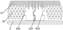
1-wall module, 2-first wall panel, 3-wall panel unit, 31-second wall panel, 32-heat preservation layer, 33-supporting keel, 41-clamping horizontal type convex keel, 411-convex keel body, 412-first bulge, 413-second bulge, 42-clamping horizontal type concave keel, 421-concave keel body, 422-first groove, 423-second groove, 43-clamping horizontal type convex and concave keel, 431-convex keel body, 432-third bulge, 433-third groove, 51-upper floor, 52-lower floor and 53-connecting piece.
Detailed Description
In order to make the objects, technical solutions and advantages of the present invention more apparent, embodiments of the present invention will be described in detail below with reference to the accompanying drawings. It should be noted that the embodiments and features of the embodiments in the present application may be arbitrarily combined with each other without conflict.
Example one
The embodiment of the application provides a horizontal assembly wall system of a card, as shown in fig. 1 to 4, the horizontal assembly wall system of the card comprises a wall module 1 erected between an upper floor and a lower floor, the wall module 1 comprises a wall unit 3 and a first wall panel 2 arranged on one side of the wall unit 3, and the upper end and the lower end of the wall module 1 are respectively connected with a connecting piece 53 to form a partition wall; the both ends of wallboard unit 3 are provided with the horizontal fossil fragments of card that are used for being connected with adjacent wallboard unit 3, and the horizontal fossil fragments of card set up along 3 direction of height of wallboard unit, and the gap between the adjacent wallboard unit 3 and the gap staggered arrangement between the adjacent first shingle nail 2.
The horizontal assembly wall system of card passes through connecting piece 53 to be fixed between last floor 51 and lower floor 52, and the horizontal assembly wall system of card includes wall body module 1, and wall body module 1 includes wallboard unit 3 and sets up the first shingle nail 2 in wallboard unit 3 one side, and wallboard unit 3 is directly made the production by the mill, and at the job site, operating personnel assembles wallboard unit 3 and first shingle nail 2 into wall body module 1. A horizontal card assembly wall system may include a plurality of wall modules 1 arranged along its length. The gaps between the adjacent wall plate units 3 and the gaps between the adjacent first wall panels 2 are arranged in a staggered mode, so that the overall sealing and sound insulation performance of the horizontal clamping assembly wall body is improved. The conventional short self-tapping screw is used, so that the connection between the wallboard unit and the opposite gypsum board (the first wall panel 2) can be completed, and the construction is quick. The labor intensity of using the spike to connect and carry out the construction production is reduced by a wide margin, and wallboard construction quality promotes by a wide margin simultaneously.
The horizontal fossil fragments of card that are used for being connected with adjacent wallboard unit 3 are provided with at wallboard unit 3's both ends, and the easy impaired drawback of limit portion when having avoided current wall body installation does not destroy heat preservation 32 during the installation, and can guarantee the good thermal-insulated sound insulation performance of whole wall body system. Simultaneously, the wall body unit can directly be made by the factory production, the heat preservation (like the rock wool board) can be in the factory with the gypsum board, fossil fragments are integrated together, become the wallboard unit that has the heat preservation, also can only be integrated as the wallboard unit of not installing the heat preservation fossil fragments and gypsum board at the factory, carry wallboard unit and insulation material to the building site, at construction site, install the heat preservation again in the wallboard unit, consequently, constitute wallboard unit 3 of wall body module 1 and reduce by a wide margin for current assembled wall module 1 weight, intensity of labour when artifical transport and installation reduces by a wide margin, be convenient for install. The adjacent wall plate units 3 are connected through the clamping horizontal type keel, the connection stability is improved, and the installation and construction are convenient and rapid.
In an exemplary embodiment, as shown in fig. 3 and 4, the wall panel unit 3 includes a second wall panel 31, and an insulation layer 32 and a keel assembly disposed on one side of the second wall panel 31, the insulation layer 32 being laid on the second wall panel 31, and the keel assembly including the aforementioned snap-in horizontal type keel. The horizontal keel of card can be the opening along the direction of height, also can be closed, links together open-ended both sides.
The keel assembly is fixed to the second shingle 31 by a self-tapping screw. The second shingle 31 may be gypsum board or other board material; the heat preservation 32 lays on second shingle nail 31, and the heat preservation 32 bonds and covers one side of whole second shingle nail 31, and the heat preservation 32 can be the rock wool, but is not limited to the rock wool board, also can be glass cotton etc. and the heat preservation 32 is installed between fossil fragments subassembly and second shingle nail 31, has reduced sound bridge and heat bridge between fossil fragments subassembly and the second shingle nail 31, and is of value to the thermal-insulated sound insulation that keeps warm.
In actual setting, the horizontal keel is installed at the end of the wall panel unit 3 through automatic nails. Specifically, the self-tapping screw sequentially passes through the end part of the second wall panel 31, the heat insulation layer 32 and the horizontal keel; meanwhile, the heat-insulating layer 32 between the horizontal keel and the second wall panel 31 is tightly pressed by the horizontal keel and the second wall panel, so that the thickness of the end part of the wall panel unit 3 (the end part of the second wall panel 31, the heat-insulating layer 32 and the horizontal keel are clamped; the thickness of the heat-insulating layer 32 is smaller or negligible) is larger than that of other parts of the wall panel unit 3 (the end part of the second wall panel 31 and the heat-insulating layer 32), and a cavity structure is formed in the wall body.
In an exemplary embodiment, as shown in fig. 3 and 4, the clip horizontal type keel includes a clip horizontal type male keel 41 and a clip horizontal type female keel 42, and the clip horizontal type male keel 41 and the clip horizontal type female keel 42 are respectively provided at both ends of the wall panel unit 3; or, the two ends of part of the wall plate unit 3 are both provided with horizontal clamping type convex keels 41, and the two ends of the wall plate unit 3 connected with the part of the wall plate unit 3 are both provided with horizontal clamping type concave keels 42.
The setting can all be the horizontal protruding fossil fragments 41 of card at wallboard unit 3 both ends, and this kind of wallboard unit 3 cooperates with wallboard unit 3 that the horizontal concave fossil fragments 42 of card all is at both ends, forms the complete wall body of a whole face (first wall body module 1 or second wall body module 1), promptly: the wall plate unit 3 has two forms, namely a wall plate unit 3 with clamping horizontal type convex keels 41 at two ends and a wall plate unit 3 with clamping horizontal type concave keels 42 at two ends; of course, the wall panel unit 3 may also be provided with a horizontal male keel 41 at one end and a horizontal female keel 42 at the other end, i.e.: only one wall panel unit 3; the horizontal clamping type male keel 41 of one wallboard unit 3 is connected and matched with the horizontal clamping type female keel 42 of the adjacent wallboard unit 3.
In an exemplary embodiment, as shown in fig. 4, the card horizontal type stud 41 includes a stud body 411 and a first protrusion 412 provided at one side of the stud body 411. The horizontal type male keel 41 further comprises a second protrusion 413 arranged on the other side of the male keel body 411, and the second protrusion 413 and the first protrusion 412 are symmetrically arranged. First protrusion 412 and second protrusion 413 are each located in the middle of the side wing. The first protrusion 412 and the second protrusion 413 may be trapezoidal bosses, or may be rectangular, semicircular, or the like.
The horizontal clamping type male keel 41 comprises a first protrusion 412 arranged on one side of the male keel body 411, and the first protrusion 412 is used for being connected and matched with the horizontal clamping type female keel 42; the horizontal protruding keel 41 further comprises a second protrusion 413 arranged on the other side of the protruding keel body 411, the second protrusion 413 and the first protrusion 412 are symmetrically arranged, processing of the horizontal protruding keel 41 is facilitated, and meanwhile the horizontal protruding keel 41 is convenient to install on the second wall panel 31.
In an exemplary embodiment, as shown in fig. 4, the snap-in type female keel 42 includes a female keel body 421 and a first groove 422 disposed at one side of the female keel body 421, the first groove 422 being configured to receive the first protrusion 412. The horizontal female keel 42 further comprises a second groove 423 arranged on the other side of the female keel body 421, and the second groove 423 and the first groove 422 are symmetrically arranged. The first groove 422 and the second groove 423 are located at the middle portion of the side wings.
The horizontal clamping type female keel 42 comprises a first groove 422 arranged on one side of a female keel body 421, and the first groove 422 is used for connecting and matching with the first protrusion 412; the horizontal type clamping concave keel 42 further comprises a second groove 423 arranged on the other side of the concave keel body 421, the second groove 423 and the first groove 422 are symmetrically arranged, the horizontal type clamping concave keel 42 can be conveniently machined, and meanwhile, the horizontal type clamping concave keel 42 can be conveniently installed on the second wall panel 31.
Prefabricated holes are processed on the horizontal clamping type concave keels, so that self-tapping screws can conveniently penetrate through the bulges and the grooves of the two horizontal clamping type keels to connect the two wallboard units 3. The size of the protrusion is slightly smaller than that of the groove, so that the protrusion can be conveniently inserted into the groove and can be tightly inserted. The prefabricated holes are distributed at intervals along the height direction of the clamping horizontal keel. At the fossil fragments side of wallboard unit, use the spike to pass from fossil fragments prefabricated hole, accomplish the connection of two adjacent wallboard unit fossil fragments convex-concave tenons to accomplish the connection of adjacent wallboard unit.
In an exemplary embodiment, as shown in fig. 3, the keel assembly further comprises a support keel 33, the support keel 33 being disposed at a middle position of the wall panel unit 3 and disposed along a height direction of the wall panel unit 3. Insulation wool is provided between the support grid 33 and the second shingle 31.
The supporting keel 33 is arranged, so that the strength of the wallboard unit 3 can be effectively improved, and the reliability of a horizontal clamping assembly wall system is improved.
In an exemplary embodiment, the insulation includes an insulation body disposed between the keel assemblies, namely: the heat preservation layer is cuboid. Or, the heat preservation is including setting up the heat preservation main part between the fossil fragments subassembly to and set up the connecting portion at heat preservation main part both ends, connecting portion set up between fossil fragments subassembly and second shingle nail, promptly: the heat-insulating layer is step-shaped.
In an exemplary embodiment, the connector 53 comprises an expansion screw and a U-shaped ceiling keel, the U-shaped ceiling keel is also fixed by the expansion screw, and an installation space of the wall panel unit 3 is formed between two vertical plates of the U-shaped ceiling keel, which extend perpendicularly to the lower floor 52, that is: the clear width of the inside of the section of the U-shaped ceiling keel is equal to the thickness of the wall plate unit 3. When the horizontal type assembly wall body system is installed, firstly, lines are drawn at the wall body positions of the roof ground (namely, an upper floor slab and a lower floor slab), the U-shaped ceiling keel is fixed on the wall body position line of the roof ground through expansion bolts, the wall plate unit 3 is installed after the U-shaped ceiling keel is installed, then the first wall panel 2 is installed at the other side of the wall plate unit 3, and the wall plate unit 3 and the first wall panel 2 form the wall body module 1. Wherein, when first shingle nail 2 of installation for connect fixed tapping screw, pass the flank of first shingle nail 2, U type world fossil fragments and wallboard unit 3's fossil fragments in proper order, promptly: after the installation is finished, the wall body module 1 and the U-shaped lumbricus are fixed through the self-tapping nails and are relatively fixed. Of course, in actual operation, the U-shaped top and bottom keel in the connecting member 53 can be selected as the L-shaped top and bottom keel according to the requirement.
In actual operation, the wallboard unit can be manufactured integrally with the keel and the gypsum board in a factory according to design requirements. Then transport wallboard unit (not installing the heat preservation) and rock wool board to the job site together, accomplish the wallboard unit and be connected the back with the world fossil fragments, install the rock wool nail on the gypsum board of wallboard unit, insert the rock wool board again on the rock wool nail, or scribble brush glue on the gypsum board, glue the rock wool board on the gypsum board, accomplish insulation material so far and install in the wallboard unit, accomplish the installation of wallboard unit opposite gypsum board at last to accomplish the installation of wall body. Of course, a factory can also directly manufacture the wallboard unit with the heat-insulating layer, the wallboard unit (provided with the heat-insulating layer) is transported to a construction site, and after the wallboard unit is connected with the U-shaped ceiling keel, the installation of the gypsum board opposite to the wallboard unit is completed, so that the installation of the wall body is completed.
Specifically, the installation of the horizontal type assembly wall body of the card may include the following steps:
in a first step, the manufacture of the wall panel unit 3 is completed. Firstly, processing a rock wool board into a step size shape according to requirements, and then placing the rock wool board on a gypsum board according to the requirements; the method is characterized in that a clamping horizontal keel is respectively placed on the two side edges of the gypsum board, a clamping horizontal convex keel 41 is installed on one side, a clamping horizontal concave keel 42 is installed on the other side (or the wall board units 3 are divided into two types, the clamping horizontal convex keel 41 is installed on the two sides of one wall board unit 3, the clamping horizontal concave keel 42 is installed on the two sides of the other wall board unit 3), the opening of the clamping horizontal keel faces the gypsum board and presses the rock wool board, the supporting keel 33 (for example, a C-shaped keel) is placed in the middle of the gypsum board, and the opening faces the gypsum board and presses the rock wool board. Then the self-tapping screw is used for screwing the other side of the gypsum board, and the gypsum board, the rock wool board and the keel component are connected together. Completing the assembly of one wall panel unit 3. The assembly of adjacent wall panel units 3 is done in the same way as above.
And secondly, finishing the installation of the wallboard unit 3. Firstly, marking lines on the wall body position of the roof ground (namely, an upper floor and a lower floor), fixing a U-shaped ceiling keel on the wall body position line of the roof ground by using expansion bolts, moving a wallboard unit 3 to an installation site, erecting a wallboard unit 3, enabling the gypsum plate surface of the wallboard unit 3 to face outwards, respectively inserting the upper part and the lower part of the wallboard unit 3 into a U-shaped keel groove installed on the roof ground, pushing the wallboard unit to a specified position along the keel groove, and connecting the side wing of the U-shaped keel and the keel of the wallboard unit 3 together by using a self-tapping screw.
The orientation of the gypsum board of the second wallboard element 3 is aligned with the orientation of the gypsum board of the first wallboard element, and the lower part of the upper part of the second wallboard unit 3 is inserted into and installed in a U-shaped keel groove on the roof ground, the second wallboard unit is pushed to the adjacent position of the first wallboard unit along the keel groove, the gypsum boards of the two wallboard units are tightly connected, the U-shaped keel side wings are connected with the keels of the second wallboard unit 3 by self-tapping nails, meanwhile, the groove on the side surface of the second wallboard unit 3 is required to be tightly abutted with the protrusion on the side surface of the first wallboard unit 3 to complete the insertion connection, and the long screws are used for connecting two keels which are clamped and laid together through the convex grooves at the keel side of the wallboard unit (prefabricated holes can be processed at the bottom surfaces of the clamping and laying type convex-concave keels at intervals, so that the first wallboard unit 3 and the second wallboard unit 3 are conveniently connected together), and the two clamping and laying type wallboard units 3 are connected together. The process is cycled to form a full-face wall.
And thirdly, installing a water and electricity pipeline.
Fourth, the gypsum board on the other side of the wall panel unit 3 (i.e., the first wall panel 2) is installed. The gypsum board (i.e. the first wall panel 2) is erected, the gypsum board is installed on the other side of the wall panel unit 3, the gypsum board is nailed on the keel of the wall panel unit 3 through short self-tapping screws, and the joint between the gypsum boards and the joint of the wall panel unit 3 are installed in a staggered mode.
In the embodiment of the application, the horizontal fossil fragments of card that limit portion set up for when adjacent wallboard unit 3 connects, still can fix the glass cotton (or rock wool etc.) of 3 limit portions of wallboard unit, avoid the glass cotton to expose and influence the plug connection effect between wallboard unit 3, guarantee that the glass cotton of 3 limit portions of wallboard unit does not receive the damage, guarantee the sound insulation effect of the horizontal assembly wall body system of card.
The horizontal assembly wall body system of card that this application embodiment provided, connect location fit through the horizontal fossil fragments of card between the wallboard unit 3, the horizontal fossil fragments of card have direction location connection function, can realize the location connection function of assembled wall body, and, adopt fossil fragments to peg graft the cooperation, it is different with the direct grafting of gypsum board in the past, damage when can avoiding the link to peg graft (the intensity of fossil fragments is far higher than the gypsum board), and, this kind of keel structure (horizontal protruding fossil fragments 41 of card, horizontal concave fossil fragments 42 of card etc.) in this application embodiment, have certain elasticity in the flank direction, can the noise absorption, improve the effect of wallboard sound insulation.
Example two
The embodiment of the application provides a horizontal type assembly wall system of a card, the main structure of which is the same as that of the first embodiment, and the difference between the first embodiment and the second embodiment is mainly described here.
In an exemplary embodiment, as shown in fig. 5 to 7, the snap-in horizontal type keel includes snap-in horizontal type male and female keels 43, and the snap-in horizontal type male and female keels 43 are respectively provided at both ends of the wall panel unit 3. The snap-in male and female keel 43 comprises a male keel body 431, a third projection 432 provided at one side of the male keel body 431, and a third groove 433 provided at the other side of the male keel body 431. The third recess 433 is arranged to receive the third projection 432 on an adjacent wall panel unit 3.
The horizontal clamping type keel comprises horizontal clamping type convex-concave keels 43, the horizontal clamping type convex-concave keels 43 are arranged at two ends of the wallboard units 3, and a third protrusion 432 of the horizontal clamping type convex-concave keel 43 of one wallboard unit 3 is connected and matched with a third groove 433 of the horizontal clamping type convex-concave keel 43 of the adjacent wallboard unit 3.
The wallboard unit has three structures, the first structure is that the tenon of the horizontal clamping type concave-convex keel 43 arranged on one side of the wallboard unit faces outwards, the tenon of the concave-convex keel 43 arranged on the other side of the wallboard unit faces outwards, and the supporting keel 33 is arranged in the middle of the wallboard unit; secondly, the tenon of the horizontal clamping type concave-convex keel 43 arranged on one side of the wallboard unit faces outwards, the tenon of the concave-convex keel 43 arranged on the other side of the wallboard unit faces outwards, and the supporting keel 33 is arranged in the middle of the wallboard unit; thirdly, the tenon of the horizontal clamping type concave-convex keel 43 arranged on one side of the wallboard unit faces outwards, the tenon of the concave-convex keel 43 arranged on the other side of the wallboard unit faces outwards, and the supporting keel 33 is arranged in the middle of the wallboard unit.
The wallboard unit uses the horizontal convex-concave keel 43, and is convenient to manufacture, construct and install.
In the description of the present invention, it should be noted that the terms "upper", "lower", "one side", "the other side", "one end", "the other end", and the like indicate orientations or positional relationships based on those shown in the drawings, and are only for convenience of describing the present invention and simplifying the description, but do not indicate or imply that the structures referred to have a specific orientation, are configured and operated in a specific orientation, and thus, are not to be construed as limiting the present invention.
In the description of the embodiments of the present invention, unless otherwise explicitly specified or limited, the terms "connected," "directly connected," "indirectly connected," "fixedly connected," "mounted," and "assembled" are to be construed broadly and may, for example, be fixedly connected, detachably connected, or integrally connected; the terms "mounted," "connected," and "fixedly connected" may be directly connected or indirectly connected through intervening media, or may be connected through two elements. The specific meanings of the above terms in the present invention can be understood in specific cases to those skilled in the art.
Although the embodiments of the present invention have been described above, the above description is only for the convenience of understanding the present invention, and is not intended to limit the present invention. It will be understood by those skilled in the art that various changes in form and details may be made therein without departing from the spirit and scope of the invention as defined by the appended claims.
Claims (14)
1. The clamping horizontal type assembly wall body system is characterized by comprising a wall body module which is erected between an upper floor slab and a lower floor slab, wherein the wall body module comprises a wall plate unit and a first wall panel arranged on one side of the wall plate unit, and the upper end and the lower end of the wall body module are respectively connected with a connecting piece to form a partition wall;
the two ends of the wall plate unit are provided with horizontal clamping keels used for being connected with the adjacent wall plate units, the horizontal clamping keels are arranged along the height direction of the wall plate unit,
gaps between the adjacent wallboard units and gaps between the adjacent first wallboard panels are arranged in a staggered mode.
2. The horizontal assembly wall system according to claim 1, wherein the wall panel unit comprises a second wall panel, and an insulation layer and a keel assembly disposed on one side of the second wall panel, the insulation layer being laid on the second wall panel,
the keel assembly comprises the horizontal clamping keel.
3. The horizontal type assembly wall system according to claim 2, wherein the horizontal type keel comprises a horizontal type male keel and a horizontal type female keel, the horizontal type male keel and the horizontal type female keel are open or closed along the height direction,
the clamping horizontal type convex keel and the clamping horizontal type concave keel are respectively arranged at two ends of the wallboard unit; or the two ends of part of the wallboard units are provided with the horizontal clamping convex keels, and the two ends of the wallboard unit connected with the part of the wallboard units are provided with the horizontal clamping concave keels.
4. The horizontal assembly wall system according to claim 3, wherein the horizontal type convex keel comprises a convex keel body and a first protrusion arranged on one side of the convex keel body.
5. The horizontal assembly wall system according to claim 4, wherein the horizontal assembly keel further comprises a second protrusion arranged on the other side of the keel body, and the second protrusion and the first protrusion are symmetrically arranged.
6. The horizontal assembly wall system according to claim 4, wherein the horizontal clip type furring channel comprises a furring channel body and a first groove provided on one side of the furring channel body, the first groove being configured to receive the first protrusion.
7. The horizontal assembly wall system according to claim 6, wherein the horizontal assembly keel further comprises a second groove arranged on the other side of the keel body, and the second groove and the first groove are symmetrically arranged.
8. The horizontal assembly wall system according to claim 2, wherein the horizontal keel comprises a horizontal keel which is open or closed in the height direction,
the horizontal clamping type convex-concave keels are respectively arranged at two ends of the wallboard unit.
9. The horizontal assembly wall system according to claim 8, wherein the horizontal male and female keel comprises a male and female keel body, a third projection provided on one side of the male and female keel body, and a third groove provided on the other side of the male and female keel body.
10. The horizontal assembly wall system according to claim 8, wherein the protrusion of the horizontal keel is a trapezoidal protrusion, a rectangular protrusion or a semicircular protrusion, and the groove of the horizontal keel is a trapezoidal groove, a rectangular groove or a semicircular groove.
11. The horizontal clamping assembly wall system according to claim 8, wherein a prefabricated hole is formed in a groove side wall of the horizontal clamping keel, a self-tapping screw is inserted into a protrusion of the horizontal clamping keel through the prefabricated hole,
the prefabricated holes are distributed at intervals along the height direction of the clamping horizontal keel.
12. The horizontal assembly wall system according to any one of claims 2 to 9, wherein the keel assembly further comprises a support keel disposed at a middle position of the wall panel unit and along a height direction of the wall panel unit.
13. The horizontal assembly wall system according to claim 8, wherein the insulating layer has a thickness less than the thickness of the keel assembly, such that a cavity is formed between the insulating layer and the first wall panel.
14. The card horizontal assembly wall system according to claim 8, wherein the insulation comprises an insulation body disposed between the keel assemblies; alternatively, the first and second electrodes may be,
the heat preservation is including setting up heat preservation main part between the fossil fragments subassembly, and set up the connecting portion at heat preservation main part both ends, connecting portion set up the fossil fragments subassembly with between the second shingle nail.
Priority Applications (1)
| Application Number | Priority Date | Filing Date | Title |
|---|---|---|---|
| CN202011614516.7A CN112854544A (en) | 2020-12-31 | 2020-12-31 | Horizontal assembly wall system of card |
Applications Claiming Priority (1)
| Application Number | Priority Date | Filing Date | Title |
|---|---|---|---|
| CN202011614516.7A CN112854544A (en) | 2020-12-31 | 2020-12-31 | Horizontal assembly wall system of card |
Publications (1)
| Publication Number | Publication Date |
|---|---|
| CN112854544A true CN112854544A (en) | 2021-05-28 |
Family
ID=75998711
Family Applications (1)
| Application Number | Title | Priority Date | Filing Date |
|---|---|---|---|
| CN202011614516.7A Pending CN112854544A (en) | 2020-12-31 | 2020-12-31 | Horizontal assembly wall system of card |
Country Status (1)
| Country | Link |
|---|---|
| CN (1) | CN112854544A (en) |
Citations (4)
| Publication number | Priority date | Publication date | Assignee | Title |
|---|---|---|---|---|
| KR20040057126A (en) * | 2002-12-24 | 2004-07-02 | 재단법인 포항산업과학연구원 | A wall structure fixed fire resistance material and absorbing material in steel stud |
| CN106401020A (en) * | 2015-07-31 | 2017-02-15 | 北新集团建材股份有限公司 | Gypsum board partition wall and connecting structure thereof |
| CN110616831A (en) * | 2019-09-20 | 2019-12-27 | 金螳螂精装科技(苏州)有限公司 | Assembled unit keel partition wall system |
| CN110872877A (en) * | 2018-08-30 | 2020-03-10 | 北新集团建材股份有限公司 | Hinge type top and bottom keel connecting piece and wall body thereof |
-
2020
- 2020-12-31 CN CN202011614516.7A patent/CN112854544A/en active Pending
Patent Citations (4)
| Publication number | Priority date | Publication date | Assignee | Title |
|---|---|---|---|---|
| KR20040057126A (en) * | 2002-12-24 | 2004-07-02 | 재단법인 포항산업과학연구원 | A wall structure fixed fire resistance material and absorbing material in steel stud |
| CN106401020A (en) * | 2015-07-31 | 2017-02-15 | 北新集团建材股份有限公司 | Gypsum board partition wall and connecting structure thereof |
| CN110872877A (en) * | 2018-08-30 | 2020-03-10 | 北新集团建材股份有限公司 | Hinge type top and bottom keel connecting piece and wall body thereof |
| CN110616831A (en) * | 2019-09-20 | 2019-12-27 | 金螳螂精装科技(苏州)有限公司 | Assembled unit keel partition wall system |
Non-Patent Citations (2)
| Title |
|---|
| 新型建筑材料专业委员会: "《新型建筑材料施工手册》", 30 April 1994, 中国建筑工业出版社 * |
| 王鹏起 等: "装配式内隔墙系统探讨", 《新型建筑材料》 * |
Similar Documents
| Publication | Publication Date | Title |
|---|---|---|
| CN110872875B (en) | Assembled wall and mounting method | |
| CN111321803B (en) | Modular assembly type building | |
| CN109972765B (en) | Three-wall two-cavity assembled wall system, wall main board and mounting method | |
| CN112814211B (en) | Mounting method of assembled wall | |
| CN110284627B (en) | Assembly type inner partition wall system and installation method thereof | |
| CN110984435A (en) | Tenon-and-mortise connected assembled partition wall and assembling method thereof | |
| CN112814216A (en) | Horizontal clamping type wall capable of accommodating pipeline and construction method | |
| CN112854546A (en) | Clamping horizontal type assembly wall system and construction method | |
| CN112443096A (en) | Wall ceramic tile installation structure and installation method | |
| CN112854544A (en) | Horizontal assembly wall system of card | |
| CN109914639B (en) | Prefabricated outer wall structure of heat preservation assembly type building | |
| CN218522129U (en) | Well wall | |
| CN215330704U (en) | End structure of assembled wall body | |
| CN112726886A (en) | Horizontal assembly wall system of card with extending structure | |
| CN215889033U (en) | Assembled wall system with cartridge wall top binding off structure | |
| CN112726887A (en) | Horizontal clamping type wall with suspension device and construction method | |
| CN112814212A (en) | Mounting method of assembled wall | |
| CN112814208A (en) | Horizontal clamping type wall with suspension device and construction method | |
| CN112854543A (en) | Door and window structure of horizontal wall body and door and window construction method | |
| CN110872876B (en) | Built-in world fossil fragments connecting piece and wall body thereof | |
| CN111705949A (en) | Assembled wall body convenient to preparation | |
| CN214498156U (en) | Wall body ceramic tile mounting structure | |
| CN203247721U (en) | Connecting structure for wallboards in same wall of precast house | |
| CN212405594U (en) | Wall module and assembled wall | |
| CN212405591U (en) | Plug-in wall module and assembled wall |
Legal Events
| Date | Code | Title | Description |
|---|---|---|---|
| PB01 | Publication | ||
| PB01 | Publication | ||
| SE01 | Entry into force of request for substantive examination | ||
| SE01 | Entry into force of request for substantive examination | ||
| RJ01 | Rejection of invention patent application after publication |
Application publication date: 20210528 |
|
| RJ01 | Rejection of invention patent application after publication |