CN112809309A - Positioning and clamping device for welding round pipe steel - Google Patents
Positioning and clamping device for welding round pipe steel Download PDFInfo
- Publication number
- CN112809309A CN112809309A CN202110251749.3A CN202110251749A CN112809309A CN 112809309 A CN112809309 A CN 112809309A CN 202110251749 A CN202110251749 A CN 202110251749A CN 112809309 A CN112809309 A CN 112809309A
- Authority
- CN
- China
- Prior art keywords
- pair
- welding
- positioning
- rotating
- clamping device
- Prior art date
- Legal status (The legal status is an assumption and is not a legal conclusion. Google has not performed a legal analysis and makes no representation as to the accuracy of the status listed.)
- Pending
Links
- 238000003466 welding Methods 0.000 title claims abstract description 73
- 229910000831 Steel Inorganic materials 0.000 title claims abstract description 36
- 239000010959 steel Substances 0.000 title claims abstract description 36
- 230000007246 mechanism Effects 0.000 claims abstract description 49
- 239000000463 material Substances 0.000 claims abstract description 9
- 238000009434 installation Methods 0.000 claims description 14
- 238000003780 insertion Methods 0.000 claims description 12
- 230000037431 insertion Effects 0.000 claims description 12
- 230000000712 assembly Effects 0.000 claims description 9
- 238000000429 assembly Methods 0.000 claims description 9
- 210000001503 joint Anatomy 0.000 claims description 9
- 238000003032 molecular docking Methods 0.000 claims description 6
- 238000013461 design Methods 0.000 abstract description 5
- 238000000034 method Methods 0.000 description 5
- 239000000758 substrate Substances 0.000 description 2
- 238000004891 communication Methods 0.000 description 1
- 238000010586 diagram Methods 0.000 description 1
- 238000003754 machining Methods 0.000 description 1
- 238000012986 modification Methods 0.000 description 1
- 230000004048 modification Effects 0.000 description 1
- 230000001360 synchronised effect Effects 0.000 description 1
Images


Classifications
-
- B—PERFORMING OPERATIONS; TRANSPORTING
- B23—MACHINE TOOLS; METAL-WORKING NOT OTHERWISE PROVIDED FOR
- B23K—SOLDERING OR UNSOLDERING; WELDING; CLADDING OR PLATING BY SOLDERING OR WELDING; CUTTING BY APPLYING HEAT LOCALLY, e.g. FLAME CUTTING; WORKING BY LASER BEAM
- B23K37/00—Auxiliary devices or processes, not specially adapted to a procedure covered by only one of the preceding main groups
- B23K37/04—Auxiliary devices or processes, not specially adapted to a procedure covered by only one of the preceding main groups for holding or positioning work
- B23K37/053—Auxiliary devices or processes, not specially adapted to a procedure covered by only one of the preceding main groups for holding or positioning work aligning cylindrical work; Clamping devices therefor
Abstract
The invention discloses a positioning and clamping device for welding round tube steel, which comprises a reference platform, an adjustable clamping mechanism, a gantry truss and a pair of welding adjusting mechanisms, wherein the reference platform is a rectangular structural platform, the adjustable clamping mechanism is arranged on one side of the reference platform, the gantry truss is assembled on the plane of the reference platform, the pair of welding adjusting mechanisms are arranged between opposite wall surfaces in the gantry truss, and movable butting mechanisms are arranged on two sides of the center line of the reference platform and between the gantry trusses; the positioning and clamping device for welding the round tube steel has the advantages that the structure is simple, the operation is convenient, the round tube steel is fixed through the rotatable adjustable clamping mechanism, the weldment is accurately butted with the base material through the welding adjusting mechanism and the movable butting mechanism which can synchronously act, then the welding is carried out, the butting pressure is reduced, the structural design is simple, and the movement line is fixed.
Description
Technical Field
The invention relates to the technical field of welding equipment, in particular to a positioning and clamping device for welding round tube steel.
Background
The steel is a material frequently used in the fields of building, machining and the like, the types of the steel are various, more steel plates, steel pipes and steel structure frames are used, the steel needs to be welded before use, the frames with different structures are spliced for use, and the outer wall of the round pipe steel is welded and butted all the time, mechanical automatic butt joint is difficult to realize, so manual welding is adopted in the round pipe steel welding stage, in the welding process, in order to realize multidirectional butt joint of a base material and a welding part, expensive equipment such as a three-axis mechanical arm is generally adopted, and equipment cost is increased.
Disclosure of Invention
The invention aims to solve the problems, designs a positioning and clamping device for welding round tube steel, and solves the problems of the prior art.
The technical scheme of the invention for realizing the aim is as follows: a positioning and clamping device for welding round tube steel comprises a reference platform, an adjustable clamping mechanism, a gantry truss and a pair of welding adjusting mechanisms, wherein the reference platform is a rectangular structural platform, the adjustable clamping mechanism is installed on one side of the reference platform, the gantry truss is assembled on the plane of the reference platform, the pair of welding adjusting mechanisms are installed between opposite wall surfaces in the gantry truss, and movable butting mechanisms are arranged on two sides of the center line of the reference platform and between the gantry trusses;
the portable docking mechanism includes: the device comprises a pair of transverse sliding rails, a pair of sliding blocks, a pair of power assemblies, a pair of stand columns, an inserted rod, an adjusting cylinder, a rotating seat, a rotating sleeve, a fixing plate, a pair of screw rods, a pair of rotating motors, two pairs of threaded sleeves and a pair of clamping blocks;
the reference table is provided with a pair of parallel transverse sliding rails on two sides of a central axis, a pair of sliding blocks are assembled on the transverse sliding rails, a pair of power components are arranged between the sliding blocks and the transverse sliding rails, a pair of upright posts are assembled on the sliding blocks, slots with cylindrical cavities are formed in the upright posts, the insertion rod is inserted into the slots, the adjusting cylinder is embedded into the slots and connected with the end parts of the insertion rod, the top end of the insertion rod is provided with a rotating seat, the rotating seat is sleeved with a rotating sleeve, a fixed plate is arranged on the rotating sleeve, a pair of parallel mounting grooves are formed in the fixed plate, a pair of lead screws are arranged in the mounting grooves, a pair of rotating motor drives are arranged at the end parts of the lead screws, two pairs of threaded sleeves are sleeved on the lead screws, and two pairs of threaded sleeve mirrors are assembled in the mounting grooves, and a pair of opposite clamping blocks is arranged on the two pairs of threaded sleeves.
The adjustable clamping mechanism comprises: the device comprises a fixed table, a sliding chute, an installation cavity, a jacking cylinder, a lifting block, a pair of connecting rods and a clamping disc;
the one end is equipped with the fixed station on the benchmark platform, set up the spout of vertical direction on the fixed station side wall face, the elevator assembles in the spout, the installation cavity has been seted up in the fixed station, the embedded jacking cylinder that is equipped with of installation cavity, the flexible end and the elevator of jacking cylinder are connected, a pair of logical groove intercommunication has been seted up between installation cavity and the spout, the flexible serving of jacking cylinder is equipped with a pair of connecting rod and runs through a pair ofly lead to the groove and be connected with the elevator, be equipped with the centre gripping dish on the elevator.
The welding adjustment mechanism includes: the welding device comprises an adjusting groove, a movable block, a welding arm, a telescopic block, a telescopic push rod, an installation block, a pair of positioning blocks, a rotating rod and a welding gun;
the gantry truss is characterized in that an adjusting groove is formed in the opposite wall surface in the gantry truss, a movable block is embedded in the adjusting groove, a welding arm is arranged on the movable block, a telescopic groove is formed in the welding arm, the telescopic block is assembled in the telescopic groove, a telescopic push rod is embedded in the telescopic groove, an installation block is arranged at the end of the telescopic block, a long circular hole is formed in the installation block, a pair of positioning blocks is assembled on the installation block, the rotating shaft penetrates through the long circular hole and is connected between the pair of positioning blocks, a rotating rod is arranged on the rotating shaft, a rotating plate is arranged at the end of the rotating rod, a welding gun is arranged on the rotating plate, and the bottom ends of the two sides of the gantry truss are connected.
An adjusting motor is embedded in the rotating seat, and the driving end of the adjusting motor is connected with the rotating sleeve.
The width of the pair of connecting rods is matched with that of the pair of through grooves.
And a pair of fastening bolts are respectively arranged at two ends of the pair of positioning blocks for connection.
The rotating plate is provided with a clamping sleeve, and the welding gun is assembled on the clamping sleeve.
A linear groove is formed in the reference table along the central axis, and an auxiliary supporting table is arranged on the linear groove and on the side opposite to the fixed table.
And two pairs of support legs are arranged at four corners of the bottom surface of the reference table.
And a pair of gaskets is arranged on the opposite wall surfaces of the clamping blocks.
The positioning and clamping device for welding the round tube steel manufactured by the technical scheme of the invention has the advantages of simple structure and convenient operation, fixes the round tube through the rotatable adjustable clamping mechanism, precisely butts the weldment with the base material through the synchronously acting welding adjusting mechanism and the movable butting mechanism, and then welds, thereby not only reducing the butting pressure, but also having simple structural design and fixed motion line.
Drawings
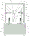
Fig. 1 is a schematic front view structural diagram of a positioning and clamping device for welding round pipes and steel products.
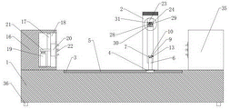
FIG. 2 is a schematic side view of the positioning and clamping device for welding round pipes and steel materials according to the present invention.
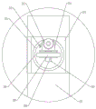
Fig. 3 is a schematic top view of the positioning and clamping device for welding round pipes and steel materials according to the present invention.
Fig. 4 is a partially enlarged structural schematic view of the positioning and clamping device for welding round pipe and steel material in fig. 1.
Fig. 5 is a partially enlarged structural schematic view of the positioning and clamping device for welding round pipe and steel material according to the invention shown in fig. 2.
In the figure: 1. a reference table; 2. a gantry truss; 3. transversely moving the sliding rail; 4. a slider; 5. a power assembly; 6. a column; 7. inserting a rod; 8. an adjusting cylinder; 9. a rotating seat; 10. rotating the sleeve; 11. a fixing plate; 12. a screw rod; 13. rotating the motor; 14. a threaded sleeve; 15. a clamping block; 16. a fixed table; 17. a chute; 18. a mounting cavity; 19. jacking a cylinder; 20. a lifting block; 21. a connecting rod; 22. a clamping plate; 23. an adjustment groove; 24. a movable block; 25. welding the arm; 26. a telescopic block; 27. a telescopic push rod; 28. mounting blocks; 29. positioning blocks; 30. rotating the rod; 31. a welding gun; 32. adjusting the motor; 33. fastening a bolt; 34. a clamping sleeve; 35. an auxiliary support table; 36. a support leg; 37. and (7) a gasket.
Detailed Description
The invention is described in detail with reference to the accompanying drawings, as shown in fig. 1-5, the embodiment is characterized by comprising a reference platform 1, an adjustable clamping mechanism, a gantry truss 2 and a pair of welding adjusting mechanisms, wherein the reference platform 1 is a rectangular structural platform, the adjustable clamping mechanism is arranged on one side of the reference platform 1, the gantry truss 2 is assembled on the plane of the reference platform 1, the pair of welding adjusting mechanisms is arranged between opposite wall surfaces in the gantry truss 2, and a movable butt joint mechanism is arranged between the gantry truss 2 and two sides of the center line of the reference platform 1; portable docking mechanism includes: the device comprises a pair of transverse sliding rails 3, a pair of sliding blocks 4, a pair of power assemblies 5, a pair of upright posts 6, an inserted link 7, an adjusting cylinder 8, a rotating seat 9, a rotating sleeve 10, a fixing plate 11, a pair of screw rods 12, a pair of rotating motors 13, two pairs of threaded sleeves 14 and a pair of clamping blocks 15; a pair of parallel transverse sliding rails 3 are arranged on two sides of a central axis of a reference platform 1, a pair of sliding blocks 4 are assembled on the pair of transverse sliding rails 3, a pair of power assemblies 5 are arranged between the pair of sliding blocks 4 and the pair of transverse sliding rails 3 for matching, a pair of upright posts 6 are assembled on the pair of sliding blocks 4, slots with cylindrical cavities are formed in the pair of upright posts 6, insertion rods 7 are inserted into the slots, adjusting cylinders 8 are embedded into the slots and connected with the end portions of the insertion rods 7, a rotating seat 9 is arranged at the top end of the insertion rods 7, a rotating sleeve 10 is sleeved on the rotating seat 9, a fixing plate 11 is arranged on the rotating sleeve 10, a pair of parallel mounting grooves are formed in the fixing plate 11, a pair of screw rods 12 are arranged in the pair of mounting grooves, a pair of rotating motors 13 are arranged at the end portions of the pair of screw rods 12, two pairs of threaded sleeves 14 are sleeved on; this pipe steel welding is with positioning and clamping device, simple structure, convenient operation, through the fixed pipe tubular product of adjustable fixture that can rotate, but through the welding adjustment mechanism and the portable docking mechanism of synchronization motion, with the accurate butt joint of weldment and substrate, then weld, not only alleviateed the pressure of butt joint, and structural design is simple, and the motion line is fixed.
All the electrical components in the present application are connected with the power supply adapted to the electrical components through the wires, and an appropriate controller should be selected according to actual conditions to meet the control requirements, and specific connection and control sequences should be obtained.
Example (b): as can be known from the attached drawings 1-5 of the specification, the positioning and clamping device for welding the round tube steel comprises a reference table 1, an adjustable clamping mechanism, a gantry truss 2 and a pair of welding adjusting mechanisms, wherein the reference table 1 is a rectangular structural platform, the adjustable clamping mechanism is arranged on one side of the reference table 1, the gantry truss 2 is assembled on the plane of the reference table 1, the pair of welding adjusting mechanisms are arranged between opposite wall surfaces in the gantry truss 2, a movable butt joint mechanism is arranged on two sides of the center line of the reference table 1 and between the gantry trusses 2, in the specific implementation process, two pairs of support legs 36 are arranged at four corners of the bottom surface of the reference table 1, the reference table 1 is used as the integral bottom support of the equipment, the round tube steel is fixed through the adjustable clamping mechanism, and the adjustment in the horizontal plane is carried out through the mutual matching of the gantry truss, the gantry truss 2 and the movable butting mechanism slide synchronously, and the movable butting mechanism can carry weldments to adjust the position of a horizontal plane, so that butting welding is facilitated;
as can be seen from fig. 1 to 5 of the specification, the mobile docking mechanism includes: the device comprises a pair of transverse sliding rails 3, a pair of sliding blocks 4, a pair of power assemblies 5, a pair of upright posts 6, an inserted link 7, an adjusting cylinder 8, a rotating seat 9, a rotating sleeve 10, a fixing plate 11, a pair of screw rods 12, a pair of rotating motors 13, two pairs of threaded sleeves 14 and a pair of clamping blocks 15, wherein the connection relationship and the position relationship are as follows;
a pair of parallel transverse sliding rails 3 are arranged on two sides of a central axis of a reference platform 1, a pair of sliding blocks 4 are assembled on the pair of transverse sliding rails 3, a pair of power assemblies 5 are arranged between the pair of sliding blocks 4 and the pair of transverse sliding rails 3 for matching, a pair of upright posts 6 are assembled on the pair of sliding blocks 4, slots with cylindrical cavities are formed in the pair of upright posts 6, insertion rods 7 are inserted into the slots, adjusting cylinders 8 are embedded into the slots and connected with the end portions of the insertion rods 7, a rotating seat 9 is arranged at the top end of the insertion rods 7, a rotating sleeve 10 is sleeved on the rotating seat 9, a fixing plate 11 is arranged on the rotating sleeve 10, a pair of parallel mounting grooves are formed in the fixing plate 11, a pair of screw rods 12 are arranged in the pair of mounting grooves, a pair of rotating motors 13 are arranged at the end portions of the pair of screw rods 12, two pairs of threaded sleeves 14 are sleeved on;
in the specific implementation process, a pair of sliding blocks 4 and a pair of transverse sliding rails 3 are matched, the synchronous movement is carried out under the driving of a pair of power assemblies 5, then a pair of upright posts 6 and a pair of sliding blocks 4 move synchronously, a pair of connecting rods 21 are matched with the widths of a pair of through grooves, an inserted rod 7 can slide on the upright posts 6 under the driving of an adjusting cylinder 8, the end part of the inserted rod 7 is provided with a rotating seat 9 matched with a rotating sleeve 10, the rotating sleeve 10 can rotate on the rotating seat 9, an adjusting motor 32 is embedded in the rotating seat 9, the driving end of the adjusting motor 32 is connected with the rotating sleeve 10, the rotating sleeve 10 can drive a fixed plate 11 to rotate, a pair of parallel screw rods 12 are arranged on the fixed plate 11, a pair of screw rods 12 are driven by a pair of rotating motors 13 to rotate to drive two pairs of threaded sleeves 14 to be meshed with the two pairs of threaded sleeves, in this way, the weldment is clamped by the pair of clamping blocks 15, the pair of gaskets 37 are arranged on the opposite wall surfaces of the pair of clamping blocks 15, and the circular tube is driven to rotate by the adjustable clamping mechanism, so that the welding position is aligned with the weldment.
As can be seen from fig. 1-5 of the specification, the adjustable clamping mechanism comprises: the device comprises a fixed table 16, a sliding chute 17, a mounting cavity 18, a jacking cylinder 19, a lifting block 20, a pair of connecting rods 21 and a clamping disc 22, wherein the connecting relationship and the position relationship are as follows;
a fixed table 16 is arranged at one end of the reference table 1, a sliding groove 17 in the vertical direction is formed in the side wall surface of the fixed table 16, a lifting block 20 is assembled in the sliding groove 17, an installation cavity 18 is formed in the fixed table 16, a jacking cylinder 19 is embedded in the installation cavity 18, the telescopic end of the jacking cylinder 19 is connected with the lifting block 20, a pair of through grooves are formed between the installation cavity 18 and the sliding groove 17 for communication, a pair of connecting rods 21 are arranged on the telescopic end of the jacking cylinder 19 and penetrate through the pair of through grooves to be connected with the lifting block 20, and a clamping disc 22 is arranged on the lifting block 20;
in the specific implementation process, a fixing table 16 is arranged on one side of a reference table 1 and serves as a main body for supporting and installing, a lifting cylinder is embedded in an installation cavity 18 and can drive a lifting block 20 to slide through a pair of connecting rods 21, the lifting block 20 is installed in a sliding groove 17 and is limited by the sliding groove 17, the end portion of a circular pipe is clamped by a clamping disc 22 while the position of the lifting block 20 is adjusted through the lifting cylinder, fixing of circular pipe workpieces with different diameters is achieved, a linear groove is formed in the reference table 1 along the central axis, an auxiliary supporting table 35 is arranged on one side, opposite to the fixing table 16, of the linear groove, and the auxiliary supporting table 35 can slide in the linear groove, so that hoisting equipment can be conveniently placed into the circular pipe.
As can be seen from fig. 1 to 5 of the specification, the welding adjusting mechanism includes: the adjusting groove 23, the movable block 24, the welding arm 25, the telescopic block 26, the telescopic push rod 27, the mounting block 28, the pair of positioning blocks 29, the rotating lever 30, and the welding gun 31 are connected and positioned as follows;
the gantry truss structure comprises a gantry truss 2, adjusting grooves 23 are formed in opposite wall surfaces in the gantry truss 2, moving blocks 24 are embedded in the adjusting grooves 23, welding arms 25 are arranged on the moving blocks 24, telescopic grooves are formed in the welding arms 25, the telescopic blocks 26 are assembled in the telescopic grooves, telescopic push rods 27 are embedded in the telescopic grooves, mounting blocks 28 are arranged at the ends of the telescopic blocks 26, long round holes are formed in the mounting blocks 28, a pair of positioning blocks 29 are assembled on the mounting blocks 28, a rotating shaft penetrates through the long round holes to be connected between the pair of positioning blocks 29, rotating rods 30 are arranged on the rotating shaft, rotating plates are arranged at the ends of the rotating rods 30, welding guns 31 are arranged on the rotating plates, and the bottom ends of.
In the specific implementation process, the vertical horizontal height can be adjusted through the adjustment groove 23 to the movable block 24, be equipped with the welding arm 25 on the movable block 24 simultaneously, be used for fixed flexible piece 26, the length that stretches out is adjusted to flexible piece 26 accessible telescopic push rod 27, and then drive welder 31 and contact the welding position, a pair of locating piece 29 both ends are equipped with a pair of fastening bolt 33 respectively and connect, be used for fixed welder 31 position in the slotted hole, be equipped with centre gripping cover 34 on the rotor plate, welder 31 assembles on centre gripping cover 34, can drive the rotor plate rotation through dwang 30, and then adjust welder 31's angle and orientation, improve welder 31's work efficiency.
To sum up, this pipe steel welding is with positioning and clamping device, simple structure, convenient operation, through the fixed pipe tubular product of adjustable fixture that can rotate, through the welding adjustment mechanism and the portable docking mechanism that can move in step, with weldment and the accurate butt joint of substrate, then weld, not only alleviateed the pressure of butt joint, and structural design is simple, and the motion line is fixed.
The technical solutions described above only represent the preferred technical solutions of the present invention, and some possible modifications to some parts of the technical solutions by those skilled in the art all represent the principles of the present invention, and fall within the protection scope of the present invention.
Claims (10)
1. A positioning and clamping device for welding round tube steel comprises a reference platform (1), an adjustable clamping mechanism, a gantry truss (2) and a pair of welding adjusting mechanisms, wherein the reference platform (1) is a rectangular structure platform, the adjustable clamping mechanism is installed on one side of the reference platform (1), the gantry truss (2) is assembled on the plane of the reference platform (1), and the pair of welding adjusting mechanisms are installed between opposite wall surfaces in the gantry truss (2), and the positioning and clamping device is characterized in that a movable butt joint mechanism is arranged on two sides of the center line of the reference platform (1) and between the gantry truss (2);
the portable docking mechanism includes: the device comprises a pair of transverse sliding rails (3), a pair of sliding blocks (4), a pair of power assemblies (5), a pair of upright posts (6), an inserted bar (7), an adjusting cylinder (8), a rotating seat (9), a rotating sleeve (10), a fixing plate (11), a pair of screw rods (12), a pair of rotating motors (13), two pairs of threaded sleeves (14) and a pair of clamping blocks (15);
the device is characterized in that a pair of parallel transverse sliding rails (3) are arranged on two sides of a central axis of the reference platform (1), a pair of sliding blocks (4) are assembled on the pair of transverse sliding rails (3), a pair of power assemblies (5) are arranged between the pair of sliding blocks (4) and the pair of transverse sliding rails (3) for matching, a pair of upright posts (6) are assembled on the pair of sliding blocks (4), slots with cylindrical cavities are formed in the pair of upright posts (6), insertion rods (7) are inserted into the slots, adjusting cylinders (8) are embedded into the slots and connected with the end portions of the insertion rods (7), rotating seats (9) are arranged at the top ends of the insertion rods (7), rotating sleeves (10) are sleeved on the rotating seats (9), fixing plates (11) are arranged on the rotating sleeves (10), a pair of parallel mounting grooves are formed in the fixing plates (11), and a pair of lead screws (12) are arranged in, the end part of the screw rod (12) is provided with a pair of rotating motors (13) for driving, the screw rod (12) is sleeved with two pairs of thread sleeves (14), the thread sleeves (14) are assembled in a pair of mounting grooves in a mirror image mode, and the thread sleeves (14) are provided with a pair of opposite clamping blocks (15).
2. The positioning and clamping device for round tube and steel welding as claimed in claim 1, wherein the adjustable clamping mechanism comprises: the device comprises a fixed table (16), a sliding chute (17), a mounting cavity (18), a jacking cylinder (19), a lifting block (20), a pair of connecting rods (21) and a clamping disc (22);
reference platform (1) is gone up one end and is equipped with fixed station (16), set up spout (17) of vertical direction on the side wall face of fixed station (16), elevator (20) assemble in spout (17), install chamber (18) have been seted up in fixed station (16), jacking cylinder (19) are equipped with to embedding in install chamber (18), the flexible end and the elevator (20) of jacking cylinder (19) are connected, a pair of logical groove intercommunication has been seted up between installation chamber (18) and spout (17), it is a pair of to be equipped with a pair of connecting rod (21) on the flexible end of jacking cylinder (19) and run through a pair of logical groove is connected with elevator (20), be equipped with centre gripping dish (22) on elevator (20).
3. The positioning and clamping device for welding round pipe and steel material as claimed in claim 1, wherein the welding adjusting mechanism comprises: an adjusting groove (23), a movable block (24), a welding arm (25), a telescopic block (26), a telescopic push rod (27), an installation block (28), a pair of positioning blocks (29), a rotating rod (30) and a welding gun (31);
adjusting grooves (23) are formed in the opposite wall surfaces in the gantry truss (2), movable blocks (24) are embedded in the adjusting grooves (23), the movable block (24) is provided with a welding arm (25), the welding arm (25) is provided with a telescopic groove, the telescopic block (26) is assembled in the telescopic groove, the telescopic push rod (27) is embedded in the telescopic groove, the end part of the telescopic block (26) is provided with a mounting block (28), the mounting block (28) is provided with a long round hole, a pair of positioning blocks (29) is assembled on the mounting block (28), the rotating shaft penetrates through the oblong holes and is connected between the pair of positioning blocks (29), the rotating shaft is provided with a rotating rod (30), a rotating plate is arranged at the end part of the rotating rod (30), a welding gun (31) is arranged on the rotating plate, the bottom ends of the two sides of the gantry truss (2) are connected with a pair of power assemblies (5).
4. The positioning and clamping device for welding round pipe and steel products as claimed in claim 1, wherein an adjusting motor (32) is embedded in the rotating seat (9), and a driving end of the adjusting motor (32) is connected with the rotating sleeve (10).
5. A positioning and clamping device for welding round tubes and steel products as claimed in claim 2, characterized in that a pair of said connecting rods (21) is matched with the width of a pair of said through slots.
6. The positioning and clamping device for welding round tubes and steel products as claimed in claim 3, wherein a pair of fastening bolts (33) are respectively arranged at two ends of a pair of positioning blocks (29) for connection.
7. The positioning and clamping device for welding round tubes and steel products as claimed in claim 3, wherein the rotating plate is provided with a clamping sleeve (34), and the welding gun (31) is assembled on the clamping sleeve (34).
8. The positioning and clamping device for welding round tubes and steel products as claimed in claim 2, wherein a linear groove is formed in the reference table (1) along the central axis, and an auxiliary supporting table (35) is arranged on the linear groove and on the side opposite to the fixing table (16).
9. The positioning and clamping device for welding round pipe and steel products as claimed in claim 1, wherein two pairs of supporting legs (36) are arranged at four corners of the bottom surface of the reference table (1).
10. The positioning and clamping device for welding round pipes and steel products as claimed in claim 1, wherein a pair of gaskets (37) are arranged on opposite wall surfaces of a pair of clamping blocks (15).
Priority Applications (1)
| Application Number | Priority Date | Filing Date | Title |
|---|---|---|---|
| CN202110251749.3A CN112809309A (en) | 2021-03-08 | 2021-03-08 | Positioning and clamping device for welding round pipe steel |
Applications Claiming Priority (1)
| Application Number | Priority Date | Filing Date | Title |
|---|---|---|---|
| CN202110251749.3A CN112809309A (en) | 2021-03-08 | 2021-03-08 | Positioning and clamping device for welding round pipe steel |
Publications (1)
| Publication Number | Publication Date |
|---|---|
| CN112809309A true CN112809309A (en) | 2021-05-18 |
Family
ID=75863014
Family Applications (1)
| Application Number | Title | Priority Date | Filing Date |
|---|---|---|---|
| CN202110251749.3A Pending CN112809309A (en) | 2021-03-08 | 2021-03-08 | Positioning and clamping device for welding round pipe steel |
Country Status (1)
| Country | Link |
|---|---|
| CN (1) | CN112809309A (en) |
Cited By (1)
| Publication number | Priority date | Publication date | Assignee | Title |
|---|---|---|---|---|
| CN113506682A (en) * | 2021-08-16 | 2021-10-15 | 曹利男 | Adjustable rotor winding winder for manufacturing transformer |
Citations (6)
| Publication number | Priority date | Publication date | Assignee | Title |
|---|---|---|---|---|
| JP2017006978A (en) * | 2015-06-26 | 2017-01-12 | 株式会社東芝 | Welding device and method |
| CN206811401U (en) * | 2017-05-26 | 2017-12-29 | 深圳市腾达丰实业有限公司 | It is a kind of to cut hole equipment for mutually passing through for pipe |
| CN110405325A (en) * | 2019-08-10 | 2019-11-05 | 深圳市首谷科技有限公司 | A kind of argon arc welding machine and its working method with heat sinking function |
| CN111375979A (en) * | 2020-05-08 | 2020-07-07 | 宁波鄞州区景行远望科技服务有限公司 | A welding ware for production of copper handicraft |
| CN211162689U (en) * | 2019-04-30 | 2020-08-04 | 江苏金猫机器人科技有限公司 | Large taper pipe welding positioner |
| CN211680764U (en) * | 2020-02-29 | 2020-10-16 | 杨诚 | Clamp for welding heating and ventilation pipe |
-
2021
- 2021-03-08 CN CN202110251749.3A patent/CN112809309A/en active Pending
Patent Citations (6)
| Publication number | Priority date | Publication date | Assignee | Title |
|---|---|---|---|---|
| JP2017006978A (en) * | 2015-06-26 | 2017-01-12 | 株式会社東芝 | Welding device and method |
| CN206811401U (en) * | 2017-05-26 | 2017-12-29 | 深圳市腾达丰实业有限公司 | It is a kind of to cut hole equipment for mutually passing through for pipe |
| CN211162689U (en) * | 2019-04-30 | 2020-08-04 | 江苏金猫机器人科技有限公司 | Large taper pipe welding positioner |
| CN110405325A (en) * | 2019-08-10 | 2019-11-05 | 深圳市首谷科技有限公司 | A kind of argon arc welding machine and its working method with heat sinking function |
| CN211680764U (en) * | 2020-02-29 | 2020-10-16 | 杨诚 | Clamp for welding heating and ventilation pipe |
| CN111375979A (en) * | 2020-05-08 | 2020-07-07 | 宁波鄞州区景行远望科技服务有限公司 | A welding ware for production of copper handicraft |
Cited By (1)
| Publication number | Priority date | Publication date | Assignee | Title |
|---|---|---|---|---|
| CN113506682A (en) * | 2021-08-16 | 2021-10-15 | 曹利男 | Adjustable rotor winding winder for manufacturing transformer |
Similar Documents
| Publication | Publication Date | Title |
|---|---|---|
| CN114535855B (en) | Heat supply pipeline butt welding tool | |
| CN215919498U (en) | Raw material welding device is used in pouring machine production | |
| CN112809309A (en) | Positioning and clamping device for welding round pipe steel | |
| CN211438828U (en) | Welding geminate transistors device | |
| CN115488561A (en) | Pipeline reinforcement sleeve group is to welding set | |
| CN114888400A (en) | Automatic welding device for elevator small door pocket | |
| CN211539878U (en) | Automatic welding device for straight welding seams on two sides of automobile rear axle housing | |
| CN219818564U (en) | Expansion joint butt welding clamp | |
| CN110773915A (en) | Double-station automatic welding device and method for construction elevator guide rail frame pieces | |
| CN219986658U (en) | Rapid alignment tool for welding automobile parts | |
| CN219293076U (en) | Constructional engineering steel construction welding set | |
| CN220178485U (en) | Multi-angle welding equipment | |
| CN212858259U (en) | Novel high efficiency welding equipment | |
| CN218341422U (en) | Automatic centering device for automatic welding of pipelines | |
| CN219704018U (en) | Flat-mouth welding device for heat pipe | |
| CN216370825U (en) | Support for welding steel structure | |
| CN218284338U (en) | Welding tool for automobile instrument beam end plate | |
| CN218964446U (en) | Workpiece positioning tool of automatic welding machine | |
| CN216882419U (en) | Welding system | |
| CN220372537U (en) | Bathroom pipe fitting welding set that welding efficiency is high | |
| CN218080903U (en) | Group welding fixture for car coupler seat assembly | |
| CN219403072U (en) | Steel pipe butt joint device | |
| CN220575315U (en) | Multifunctional positioning device for machining mechanical arm | |
| CN219212034U (en) | Automatic welding device | |
| CN219131329U (en) | Support piece spin welding frock |
Legal Events
| Date | Code | Title | Description |
|---|---|---|---|
| PB01 | Publication | ||
| PB01 | Publication | ||
| SE01 | Entry into force of request for substantive examination | ||
| SE01 | Entry into force of request for substantive examination | ||
| RJ01 | Rejection of invention patent application after publication | ||
| RJ01 | Rejection of invention patent application after publication |
Application publication date: 20210518 |