CN112775224A - Bending machine capable of feeding and discharging materials in multiple directions - Google Patents
Bending machine capable of feeding and discharging materials in multiple directions Download PDFInfo
- Publication number
- CN112775224A CN112775224A CN202110109863.2A CN202110109863A CN112775224A CN 112775224 A CN112775224 A CN 112775224A CN 202110109863 A CN202110109863 A CN 202110109863A CN 112775224 A CN112775224 A CN 112775224A
- Authority
- CN
- China
- Prior art keywords
- frame
- bending
- positioning
- transverse moving
- driving
- Prior art date
- Legal status (The legal status is an assumption and is not a legal conclusion. Google has not performed a legal analysis and makes no representation as to the accuracy of the status listed.)
- Pending
Links
Images


Classifications
-
- B—PERFORMING OPERATIONS; TRANSPORTING
- B21—MECHANICAL METAL-WORKING WITHOUT ESSENTIALLY REMOVING MATERIAL; PUNCHING METAL
- B21D—WORKING OR PROCESSING OF SHEET METAL OR METAL TUBES, RODS OR PROFILES WITHOUT ESSENTIALLY REMOVING MATERIAL; PUNCHING METAL
- B21D7/00—Bending rods, profiles, or tubes
-
- B—PERFORMING OPERATIONS; TRANSPORTING
- B21—MECHANICAL METAL-WORKING WITHOUT ESSENTIALLY REMOVING MATERIAL; PUNCHING METAL
- B21C—MANUFACTURE OF METAL SHEETS, WIRE, RODS, TUBES OR PROFILES, OTHERWISE THAN BY ROLLING; AUXILIARY OPERATIONS USED IN CONNECTION WITH METAL-WORKING WITHOUT ESSENTIALLY REMOVING MATERIAL
- B21C51/00—Measuring, gauging, indicating, counting, or marking devices specially adapted for use in the production or manipulation of material in accordance with subclasses B21B - B21F
-
- B—PERFORMING OPERATIONS; TRANSPORTING
- B21—MECHANICAL METAL-WORKING WITHOUT ESSENTIALLY REMOVING MATERIAL; PUNCHING METAL
- B21D—WORKING OR PROCESSING OF SHEET METAL OR METAL TUBES, RODS OR PROFILES WITHOUT ESSENTIALLY REMOVING MATERIAL; PUNCHING METAL
- B21D43/00—Feeding, positioning or storing devices combined with, or arranged in, or specially adapted for use in connection with, apparatus for working or processing sheet metal, metal tubes or metal profiles; Associations therewith of cutting devices
- B21D43/003—Positioning devices
-
- B—PERFORMING OPERATIONS; TRANSPORTING
- B21—MECHANICAL METAL-WORKING WITHOUT ESSENTIALLY REMOVING MATERIAL; PUNCHING METAL
- B21D—WORKING OR PROCESSING OF SHEET METAL OR METAL TUBES, RODS OR PROFILES WITHOUT ESSENTIALLY REMOVING MATERIAL; PUNCHING METAL
- B21D53/00—Making other particular articles
- B21D53/02—Making other particular articles heat exchangers or parts thereof, e.g. radiators, condensers fins, headers
-
- B—PERFORMING OPERATIONS; TRANSPORTING
- B21—MECHANICAL METAL-WORKING WITHOUT ESSENTIALLY REMOVING MATERIAL; PUNCHING METAL
- B21D—WORKING OR PROCESSING OF SHEET METAL OR METAL TUBES, RODS OR PROFILES WITHOUT ESSENTIALLY REMOVING MATERIAL; PUNCHING METAL
- B21D7/00—Bending rods, profiles, or tubes
- B21D7/16—Auxiliary equipment, e.g. for heating or cooling of bends
Abstract
The invention relates to a bending machine capable of feeding and discharging materials in multiple directions, which is technically characterized by comprising the following components: a bending system; a feeding system capable of feeding and pushing the workpiece to and from the bending system from one or more of the directions of the bending system; the bending system comprises a first transverse moving mechanism, a second transverse moving mechanism and a follow-up mechanism for receiving a workpiece pushed by the feeding system; the first transverse moving mechanism is provided with a first bending mechanism for bending the workpiece and a first lifting power device for driving the first bending mechanism to move up and down; the second transverse moving mechanism is provided with a second bending mechanism for bending the workpiece and a second lifting power device for driving the second bending mechanism to move up and down. The workpiece bending device is simple in structure, the first bending mechanism and the second bending mechanism can move vertically and transversely, so that workpieces cannot be blocked, and the workpieces can be fed in multiple directions.
Description
[ technical field ] A method for producing a semiconductor device
The invention relates to a bending machine on a bending machine.
[ background of the invention ]
The heat exchanger or the condenser can be bent according to actual needs. In the prior art, the bending mechanism is fixed, so that the bending mechanism can block workpieces during feeding and discharging, the feeding direction and the discharging direction of the bending machine can be limited, and particularly, the workpieces are troublesome to move during multiple bending, and the working efficiency is low.
[ summary of the invention ]
The invention aims to overcome the defects of the prior art and provides the bending machine which is simple in structure, low in cost and high in efficiency and can feed and discharge materials in multiple directions.
In order to solve the problems, the invention adopts the following technical scheme:
a multi-directional feeding and discharging bending machine is characterized by comprising:
a bending system;
a feeding system capable of feeding and pushing the workpiece to and from the bending system from one or more of the directions of the bending system;
the bending system comprises a first transverse moving mechanism, a second transverse moving mechanism and a follow-up mechanism for receiving a workpiece pushed by the feeding system;
the first transverse moving mechanism is provided with a first bending mechanism for bending the workpiece and a first lifting power device for driving the first bending mechanism to move up and down;
the second transverse moving mechanism is provided with a second bending mechanism for bending the workpiece and a second lifting power device for driving the second bending mechanism to move up and down;
the bending machine capable of feeding and discharging materials in multiple directions is characterized in that: the bending system comprises a first bending mechanism, a second bending mechanism, a follow-up mechanism, a first transverse moving mechanism and a second transverse moving mechanism, wherein the follow-up mechanism is arranged between the first bending mechanism and the second bending mechanism, the first transverse moving mechanism comprises a first transverse moving frame arranged on the first frame in a transversely movable mode and a first transverse moving power device driving the first transverse moving frame to move, and the second transverse moving mechanism comprises a second transverse moving frame arranged on the first frame in a transversely slidable mode and a second transverse moving power device driving the second transverse moving frame to move transversely.
The bending machine capable of feeding and discharging materials in multiple directions is characterized in that: the first transverse moving power device is a linear driving mechanism arranged on the first transverse moving frame and used for driving the first transverse moving frame to move linearly, and the second transverse moving power device is a linear driving mechanism arranged on the second transverse moving frame and used for driving the second transverse moving frame to move linearly.
The bending machine capable of feeding and discharging materials in multiple directions is characterized in that: first bending mechanism include and establish the first installation curved frame on first sideslip frame with sliding from top to bottom, first installation curved frame on rotationally be equipped with first pivot, drive first pivot pivoted first rotation actuating mechanism, first pivot on be equipped with and drive pivoted first linkage, can rotate ground cover first epaxial first rod relatively, first linkage on be equipped with first carriage and drive first carriage elevating gear that first carriage reciprocated, first carriage on can be equipped with first carriage and drive that can drag the work piece with lateral shifting first carriage lateral shifting drive arrangement.
The bending machine capable of feeding and discharging materials in multiple directions is characterized in that: the second mechanism of bending include that the second of establishing on second sideslip power frame with sliding from top to bottom is bent the installation, the second bend the installation on rotationally be equipped with second pivot, drive second pivot pivoted second rotation actuating mechanism, the second pivot on be equipped with and drive pivoted second linkage frame, can rotate relatively ground cover second commentaries on classics rod in the epaxial second of second commentaries on classics, the second change rod on be equipped with the splint that can press from both sides the work piece, the second linkage on can be equipped with second carriage frame and the drive that can clip the work piece with splint with reciprocating second carriage frame that reciprocates second carriage frame reciprocated, second carriage frame on be equipped with the locating lever carriage to work piece tip transverse positioning.
The bending machine capable of feeding and discharging materials in multiple directions is characterized in that: the second frame on be equipped with and to lean on the backup plate subassembly, drive backup plate subassembly lateral shifting power device that leans on the work piece of first mechanism one side to serve, the backup plate subassembly include by backup plate lateral shifting power device drive at first frame lateral shifting's backup plate sideslip frame, establish backup plate mounting bracket on the backup plate sideslip frame, the backup plate lift power device that drives backup plate mounting bracket and reciprocate, can rotationally establish backup plate, drive backup plate pivoted backup plate rotation drive device that leans on the work piece on the backup plate mounting bracket by backup plate sideslip power device drive from top to bottom with sliding, the backup plate on be equipped with two vertical relative settings and be used for cliping the clamp splice of work piece both sides, drive two the clamp splice be close to relatively or the clamp splice power device who keeps away from.
The bending machine capable of feeding and discharging materials in multiple directions is characterized in that: and a second positioning mechanism for positioning the workpiece and a second lifting mechanism for driving the second positioning mechanism to lift are arranged on one side of the follow-up mechanism, which is far away from the material pushing system.
The bending machine capable of feeding and discharging materials in multiple directions is characterized in that: second positioning mechanism including vertically establishing the second locating rack on servo mechanism, the second locating rack on be equipped with can be on the second locating rack longitudinal movement's locating component, drive locating component longitudinal movement's location indulge and move drive arrangement, locating component including can be on the second locating rack longitudinal movement's location carriage, can be on the location carriage gliding location mounting bracket from top to bottom, fix and can be to work piece location second transverse orientation pole on the location mounting bracket, second elevating system including establishing the chute that sets up at second locating rack tip and downward sloping, the location mounting bracket on be equipped with and can slide into when the location mounting bracket longitudinal movement the chute in the pulley.
The bending machine capable of feeding and discharging materials in multiple directions is characterized in that: the feeding system comprises a first machine frame, a feeding platform for placing a workpiece and a material pushing mechanism for pushing the workpiece to move to one side of the bending system are arranged on the first machine frame, and the material pushing mechanism comprises a material pushing frame, a longitudinal moving driving mechanism for driving the material pushing frame to longitudinally move, a material pushing rod movably arranged on the material pushing frame and a material pushing power device for driving the material pushing rod to push the workpiece.
The bending machine capable of feeding and discharging materials in multiple directions is characterized in that: the first rack is also provided with a detection mechanism for detecting the size of the workpiece, a first positioning mechanism which is close to one side of the bending system and can position the workpiece when the pushing mechanism pushes the workpiece, and a first lifting mechanism for driving the first positioning mechanism to lift.
The invention has the following beneficial effects: the first bending mechanism and the second bending mechanism respectively move transversely and lift up and down through the power device, so that the bending mechanism can be withdrawn after bending is completed each time, interference of feeding and discharging on workpieces is prevented, the workpieces can be fed and discharged in multiple directions (for example, the feeding and discharging are in the longitudinal direction), feeding and discharging can be flexibly arranged according to the implementation requirements of fields, the size requirements of the workpieces and the requirements of processes, the use is convenient, and the working efficiency is high; one side of the first bending mechanism is provided with a backup plate assembly, and the backup plate is driven to rotate by a backup plate rotation driving device, so that the backup plate propping position can be adjusted according to different positions and angles of a workpiece after being bent, and the use is convenient; the clamping blocks are arranged on the backup plate, the backup plate leans against the end face of the workpiece, and the clamping blocks clamp two sides of the workpiece, so that the fins of the workpiece are prevented from being staggered during bending, and the yield is improved; the first frame is provided with a detection mechanism, during detection, the material pushing mechanism pushes the workpiece to one side of the first positioning mechanism, the first positioning mechanism positions the workpiece, then the detection mechanism measures the dimension (length, thickness and the like) of the workpiece, after the detection is qualified, the first lifting mechanism descends, the first positioning mechanism does not block the workpiece, the material pushing mechanism is started again, and the workpiece is pushed to the bending machine, so that the detection and feeding processes are realized, and the defective rate is reduced.
[ description of the drawings ]
Fig. 1 is a perspective view of a first embodiment of the present invention;
FIG. 2 is a perspective view of the bending system of the present invention;
FIG. 3 is a perspective view of the follower mechanism of the present invention;
FIG. 4 is a bottom view of the follower mechanism of the present invention;
FIG. 5 is a perspective view of a component of the follower mechanism of the present invention;
FIG. 6 is a perspective view of a second positioning mechanism of the present invention;
FIG. 7 is a left side view of a second positioning mechanism of the present invention;
FIG. 8 is a perspective view of a first bending mechanism of the present invention;
FIG. 9 is a bottom view of the first bending mechanism of the present invention;
FIG. 10 is an exploded view of a first bending mechanism of the present invention;
FIG. 11 is a perspective view of a backup plate assembly of the present invention;
FIG. 12 is a bottom view of the fence assembly of the present invention;
FIG. 13 is an exploded view of the fence assembly of the present invention;
FIG. 14 is a perspective view of a second bending mechanism of the present invention;
FIG. 15 is a left side view of a second bending mechanism of the present invention;
FIG. 16 is an exploded view of a second bending mechanism of the present invention;
FIG. 17 is a perspective view of the pusher system of the present invention;
FIG. 18 is a right side view of the pusher system of the present invention;
FIG. 19 is a perspective view of components of the pusher system of the present invention;
FIG. 20 is an exploded view of the components of the pusher system of the present invention;
FIG. 21 is a schematic view of a second embodiment of the present invention;
fig. 22 is a schematic view of a third embodiment of the present invention.
[ detailed description ] embodiments
The invention is described in further detail below with reference to the following detailed description and accompanying drawings:
as shown in fig. 1 to 22, a bending machine capable of multi-directionally feeding and discharging materials is characterized by comprising:
a bending system 10;
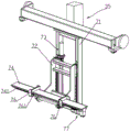
a feeding system 20 capable of feeding and pushing the workpiece to and from the bending system 10 from one or more directions of the bending system 10, wherein the feeding system 20 may be disposed at one or more sides of the bending system 10, the feeding system 20 may be mechanically powered to push the workpiece to the bending system 10 or push the bent workpiece out, and the feeding system 20 may also be manually fed; for example, the feeding system 20 may be on the left side of the bending system 10 (embodiment one), the feeding system 20 pushes the workpiece from the left side of the bending system 10 to the bending system 10, the workpiece may be pushed to the feeding system 20 for discharging after being bent, or pushed by the feeding system 20 for discharging from the right side of the bending system 10; the feeding system 20 can also be arranged at the left side and the right side of the bending system 10 (embodiment II); the feeding system 20 can also be arranged at the left, right, front and back sides of the bending system 10 (embodiment three);
the bending system 10 comprises a first transverse moving mechanism 30, a second transverse moving mechanism 40 and a follow-up mechanism 50 for receiving the workpiece pushed by the feeding system 20;
the first transverse moving mechanism 30 is provided with a first bending mechanism 4 for bending the workpiece and a first lifting power device 60 for driving the first bending mechanism 4 to move up and down;
a second bending mechanism 5 for bending the workpiece and a second lifting power device 70 for driving the second bending mechanism 5 to move up and down are arranged on the second transverse moving mechanism 40 in a vertically movable manner;
the following mechanism 5 is disposed between the first bending mechanism 4 and the second bending mechanism 5, the first bending mechanism 4 and the second bending mechanism 5 are disposed in a spaced manner, a direction from the first bending mechanism 4 to the second bending mechanism 5 is defined as a transverse direction, or a longitudinal direction of the workpiece is defined as a transverse direction, a direction horizontal to the transverse direction is defined as a longitudinal direction, and the transverse direction and the longitudinal direction are defined only for convenience of description.
The bending system 10 comprises a first rack 1, a follow-up mechanism 50 comprises a follow-up frame capable of moving transversely on the first rack 1 and a follow-up platform capable of moving up and down on the follow-up frame, a workpiece is pushed onto the follow-up platform by a feeding system 20, the first rack 1 is provided with a transversely arranged guide rail, the follow-up frame is slidably arranged on the guide rail and can be driven by a power device to move transversely, and the power device can be a hydraulic cylinder to push the follow-up frame; a rack can be arranged on the follow-up frame, and the follow-up frame drives the gear to move on the rack through a motor; certainly, the nut seat and the screw rod can be arranged on the follow-up frame, the first machine frame 1 drives the screw rod to rotate through the motor, and certainly, the mode that the motor drives the synchronous belt can also be adopted. The servo platform can be driven to lift through a power device, the vertical guide rail is arranged on the servo frame, the servo platform can be arranged on the vertical guide rail in a sliding mode, and the servo platform can be driven to lift through a cylinder or a motor in a screw rod and nut seat driving mode.
The top of the first frame 1 is provided with a transverse guide rail, the first traverse mechanism 30 comprises a first traverse frame 31 which is arranged on the first frame 1 in a transversely movable manner, and a first traverse power device 33 which drives the first traverse frame 31 to move, the first traverse frame 31 is arranged on the transverse guide rail in a slidable manner, the first traverse power device 33 is a linear driving mechanism which is arranged on the first traverse frame 31 and drives the first traverse frame 31 to move linearly, the linear driving mechanism can be a gear rack mechanism, a screw nut seat mechanism, a synchronous belt mechanism, or a hydraulic cylinder mechanism, for example, a rack is arranged at the top of the first frame 1, a motor is arranged on the first traverse frame 31, and a gear is arranged on the motor and is matched with the rack. The second traverse mechanism 40 includes a second traverse frame 51 provided on the first frame 1 to be laterally slidable, and a second traverse power unit 53 for driving the second traverse frame 51 to move laterally. The second traverse power device 53 is a linear driving mechanism provided in the second traverse frame 51 to drive the second traverse frame 51 to linearly move, and the linear driving mechanism of the second traverse power device 53 may be implemented in the same manner as the linear driving mechanism of the first traverse power device 33.
First bending mechanism 4 includes that can establish the first curved frame 42 of installing on first sideslip frame 31 with sliding from top to bottom, and first sideslip frame 31 and the first curved frame 42 of installing realize sliding from top to bottom through the mode of guide rail guide slot, and first lift power device 60 drives the first curved frame 42 of installing and reciprocates, and first lift power device 60 can be that set up vertical rack on first curved frame 42 of installing, sets up the mode drive vertical rack of motor drive gear on first sideslip frame 31. The first folding installation bent frame 42 is rotatably provided with a first rotating shaft 43 and a first rotating driving mechanism 34 for driving the first rotating shaft 43 to rotate, the first rotating driving mechanism 34 can be that a synchronous belt device is arranged on the first folding installation bent frame 42 to drive the first rotating shaft 43 to rotate, namely, a motor, a transmission rod and a transmission rod are arranged at the top of the folding installation bent frame 42 to drive the transmission belt, and the transmission belt drives the first rotating shaft 43 to rotate; of course, the first rotation driving mechanism 34 may also be a mode that a gear is driven by a motor, and the gear drives the first rotating shaft 43 to rotate. The first rotating shaft 43 is provided with a first connecting linkage frame 44 driven by the first rotating shaft 43 to rotate, and a first rotating rod 45 sleeved on the first rotating shaft 43 in a relatively rotatable manner, the first rotating rod 45 bends and guides a workpiece during bending, the upper end of the first connecting linkage frame 44 is fixed on the first rotating shaft 43, and the first rotating shaft 43 drives the first connecting linkage frame 44 to overturn during rotation. The first linkage frame 44 is provided with a first pallet frame 46 and a first pallet lifting device 49 for driving the first pallet frame 46 to move up and down, the first linkage frame 44 and the first pallet frame 46 can slide in a guide rail guiding manner, the first pallet lifting device 49 can be realized in a cylinder or a screw and nut frame or the like, for example, the first linkage frame 44 is provided with a cylinder, and the first pallet frame 46 is pushed by the shaft of the cylinder to move up and down. The first carriage frame 46 is provided with a first carriage 47 capable of dragging a workpiece and a carriage transverse moving driving device 48 for driving the first carriage 47 to transversely move, the first carriage 47 can transversely move, so that the first carriage 47 can follow the workpiece during bending, the carriage transverse moving driving device 48 can be in a screw rod and nut seat mode, a nut seat is arranged on the first carriage 47, a motor drives the screw rod to rotate, the first carriage frame 46 can also be provided with a motor to drive a gear, and a rack meshed with the gear is arranged on the first carriage 47.
The second bending mechanism 5 includes a second bending installation frame 52 slidably disposed on the second moving frame 51 up and down, the second moving frame 51 and the second bending installation frame 52 slide by means of a guide rail and a guide groove, the second elevating power device 70 drives the second bending installation frame 52 to move up and down, and the second elevating power device 70 and the first elevating power device 60 may be implemented in the same manner. The second folding and mounting bent frame 52 is rotatably provided with a second rotating shaft 54 and a second rotating driving mechanism 55 for driving the second rotating shaft 54 to rotate, and the second rotating driving mechanism 55 can be implemented in the same manner as the first rotating driving mechanism 34. The second rotating shaft 54 is provided with a second linkage frame 56 driven by the second rotating shaft 54 to rotate, and a second rotating rod 57 sleeved on the second rotating shaft 54, the second rotating rod 57 can rotate along with the second rotating shaft 54, the upper end of the second linkage frame 56 is fixed on the second rotating shaft 54, the second rotating rod 57 is provided with a clamping plate 571 capable of clamping a workpiece, the second linkage frame 56 is provided with a second carriage lifting device 59 capable of vertically moving with the clamping plate 571 to clamp the workpiece, and driving the second carriage lifting device 58 to vertically move, the second carriage lifting device 59 can be the same as the first rotating driving mechanism 34, and the second carriage positioning rod 581 for transversely positioning the end part of the workpiece is arranged on the second carriage 58.
In order to position the workpiece bending end of the first bending mechanism 4, the second frame 3 is provided with a backup plate assembly 7 which can lean against the workpiece bending end on one side of the first bending mechanism 4, and a backup plate transverse moving power device 35 which drives the backup plate assembly 7 to transversely move, and the backup plate transverse moving power device 35 can be realized in the same way as the first transverse moving power device 33. The backup plate assembly 7 comprises a backup plate transverse moving frame 71 driven by a backup plate transverse moving power device 35 to transversely move on the first frame 3, a backup plate mounting frame 72 arranged on the backup plate transverse moving frame 71 in a vertically sliding manner, a backup plate lifting power device 73 driving the backup plate mounting frame 72 to move up and down, a backup plate 74 rotatably arranged on the backup plate mounting frame 72 and capable of leaning on a workpiece, and a backup plate rotation driving device 75 driving the backup plate 74 to rotate, wherein a backup plate rotating shaft 721 is rotatably arranged on the backup plate mounting frame 72, the bottom end of the backup plate 74 is fixed on the backup plate rotating shaft 721, the backup plate rotation driving device 75 comprises a backup plate rotation driving motor 751 capable of driving the backup plate rotating shaft 721 to rotate, the backup plate rotation driving motor 751 can drive the backup plate rotating shaft 721 to rotate by means of a gear or a synchronous belt, the backup plate transverse moving frame 71 and the backup plate mounting frame 72 can move up and down by means of a guide rail and a guide groove, the backup plate lifting power device 73 can be realized, but can also be realized by the pushing of the air cylinder. The backup plate 74 is provided with two clamping blocks 76 which are longitudinally and oppositely arranged and used for clamping two sides of a workpiece, and a clamping block power device 77 for driving the two clamping blocks 76 to be relatively close to or far away from each other, wherein the clamping block power device 77 can be realized by a screw rod and two nut seats with different rotation directions, and the two clamping blocks 76 are respectively provided with the nut seats with different rotation directions; of course, the clamping block power device 77 may be a conveyor belt, and a motor drives the conveyor belt in a loop shape, and the two clamping blocks 76 are respectively arranged on two opposite belt sheets.
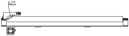
The follow-up mechanism 50 is provided with a second positioning mechanism 61 for positioning the workpiece and a second lifting mechanism 62 for driving the second positioning mechanism 61 to lift, the second positioning mechanism 61 is used for positioning the workpiece when the feeding system 20 sends the workpiece to the follow-up mechanism 50, and after the workpiece is bent, the second positioning mechanism 61 descends, and the workpiece can be pushed out by the feeding system 20. The second positioning mechanism 61 includes a second positioning frame 611 longitudinally disposed on the following mechanism 6, the second positioning frame 611 is provided with a positioning assembly 612 capable of longitudinally moving on the second positioning frame 611, and a positioning longitudinal movement driving device 66 for driving the positioning assembly 612 to longitudinally move, the positioning longitudinal movement driving device 66 may drive the positioning assembly 612 to longitudinally move by means of a synchronous belt, or certainly, may be a matching manner of a screw rod and a nut seat. The positioning assembly 612 comprises a positioning sliding frame 613 capable of longitudinally moving on the second positioning frame 611, a positioning mounting frame 614 capable of vertically sliding on the positioning sliding frame 613, a second transverse positioning rod 615 fixed on the positioning mounting frame 614 and capable of positioning a workpiece, the positioning sliding frame 613 and the positioning mounting frame 614 realize vertical relative movement through the arrangement of vertical sliding rail sliding guide, the second lifting mechanism 62 comprises a chute 621 arranged at the end part of the second positioning frame 611 and inclined downwards, a pulley 616 capable of sliding into the chute 621 when the positioning mounting frame 614 longitudinally moves is arranged on the positioning mounting frame 614, and the positioning mounting frame 614 can sink after the positioning mounting frame 614 slides into the lower end of the chute 621 due to the inclined downwards arrangement of the chute 621.
The feeding system 20 comprises a first machine frame 2, a feeding platform 21 for placing a workpiece and a pushing mechanism 22 for pushing the workpiece to move towards one side of the bending system 10 are arranged on the first machine frame 2, the pushing mechanism 22 comprises a pushing frame 226, a longitudinal movement driving mechanism 222 for driving the pushing frame 226 to move longitudinally, a pushing rod 227 movably arranged on the pushing frame 226 and a pushing power device 228 for driving the pushing rod 227 to push the workpiece, and the longitudinal movement driving mechanism 222 can realize longitudinal movement of the pushing frame 226 through a synchronous belt, a screw nut seat, an air cylinder and other modes; in this embodiment, the longitudinal movement driving mechanism 222 is a motor-driven material pushing conveyor belt 225, and a material pushing frame 226 driven by the material pushing conveyor belt 225 to move longitudinally, a plurality of material pushing rods 227 are longitudinally and telescopically arranged on the material pushing frame 226, and a material pushing cylinder 228 driving the material pushing rods 227 to stretch and retract is arranged on the material pushing frame 226, the material pushing mounting frames 221 are arranged at intervals in the transverse direction, a plurality of material pushing mounting frames 221 are connected in series by a material pushing driven rotating rod 224 and a material pushing driving rotating rod 223, two ends of the material pushing conveyor belt 225 are respectively wound on the driven rotating rod 224 and the material pushing driving rotating rod 223, the material pushing driving rotating rod 223 is driven by the material pushing conveyor belt 225 to rotate when rotating, a rotating wheel is arranged on the material pushing driving rotating rod 223. The feeding platform 21 is provided with a plurality of blocks along the transverse direction, the pushing installation frame 221 is provided with a longitudinally extending pushing guide rail 229, and the pushing frame 226 is provided with a pushing guide groove 220 which can be slidably clamped. The first frame 2 is further provided with a detection mechanism 23 for detecting the size of the workpiece, a first positioning mechanism 24 which is close to one side of the bending system 10 and can position the workpiece when the pushing mechanism 22 pushes the workpiece, and a first lifting mechanism 25 for driving the first positioning mechanism 24 to lift. The first positioning mechanism 24 includes a first positioning mounting frame 241 arranged on the first frame 2, and a positioning rod 242 which can vertically block the workpiece and is arranged on the first positioning mounting frame 241 in a vertically sliding manner, and the first positioning mounting frame 241 is arranged on one side close to the bending machine. The first lifting mechanism 25 is a lifting cylinder provided on the first positioning mounting rack 241 and capable of driving the positioning rod 241 to lift. The detecting mechanism 23 may be a thickness detecting mechanism and/or a length detecting mechanism, the thickness detecting mechanism may be an ultrasonic thickness detecting instrument, and the length detecting mechanism may be a mechanism for measuring the length of the workpiece by an infrared sensor. The first positioning mechanism 24 may be a positioning rod, and the first lifting mechanism 25 may be a cylinder that drives the positioning rod to lift up and down. During detection, the material pushing rod 227 pushes the workpiece to enable the workpiece to lean against the positioning rod, then the detection mechanism 23 carries out size detection, and after the workpiece is qualified, the positioning rod faces downwards, and the material pushing rod 227 pushes the workpiece to the follow-up mechanism 50. The detecting structure 23 includes a moving detecting rod 231 provided on the first frame 2, a fixed detecting rod 232 provided at a distance from the sliding detecting rod 23 in a lateral direction, a first detector 233 provided on the sliding detecting rod 231, a second detector 234 provided on the fixed detecting rod 232, and a moving detecting driving device 235 for driving the sliding detecting rod 231 to move, the first frame 2 is provided with a detecting guide rack 26 and a detecting guide rail 27 which are provided in a lateral direction, the moving detecting rod 231 is provided with a detecting guide groove 236 slidably clamped on the detecting guide rail 27, the moving detecting driving device 235 includes a moving detecting driving motor 237 provided on the moving detecting rod 231, and the moving detecting driving motor 237 is provided with a moving detecting driving gear 238 engaged with the detecting guide rack 26. The first detector 233 and the second detector 234 are disposed opposite to each other, and may be infrared sensors, and transmit and receive signals, and calculate a distance therebetween, thereby measuring the size of the workpiece. The detecting mechanism 23 may further include a thickness measuring instrument 239 provided on the first frame 2 for detecting the thickness of the tool, wherein the thickness measuring instrument 239 is an ultrasonic measuring instrument.
Claims (10)
1. A multi-directional feeding and discharging bending machine is characterized by comprising:
a bending system (10);
a feeding system (20) capable of feeding and pushing workpieces to and from the bending system (10) from one or more of the directions of the bending system (10);
the bending system (10) comprises a first transverse moving mechanism (30), a second transverse moving mechanism (40) and a follow-up mechanism (50) for receiving the workpieces pushed by the feeding system (20);
a first bending mechanism (4) for bending the workpiece and a first lifting power device (60) for driving the first bending mechanism (4) to move up and down are arranged on the first transverse moving mechanism (30) in a vertically movable manner;
the second transverse moving mechanism (40) is provided with a second bending mechanism (5) capable of bending the workpiece in a vertical moving way and a second lifting power device (70) driving the second bending mechanism (5) to move vertically.
2. The bending machine capable of multi-directionally feeding and discharging materials according to claim 1, wherein: the servo mechanism (50) is arranged between the first movable bending mechanism (4) and the second movable bending mechanism (5), the bending system (10) further comprises a first rack (1), the first transverse moving mechanism (30) comprises a first transverse moving frame (31) arranged on the first rack (1) in a transversely movable mode and a first transverse moving power device (33) driving the first transverse moving frame (31) to move, and the second transverse moving mechanism (40) comprises a second transverse moving frame (51) arranged on the first rack (1) in a transversely sliding mode and a second transverse moving power device (53) driving the second transverse moving frame (51) to move transversely.
3. The bending machine capable of multi-directionally feeding and discharging materials according to claim 2, wherein: the first transverse moving power device (33) is a linear driving mechanism which is arranged on the first transverse moving frame (31) and drives the first transverse moving frame (31) to move linearly, and the second transverse moving power device (53) is a linear driving mechanism which is arranged on the second transverse moving frame (51) and drives the second transverse moving frame (51) to move linearly.
4. The bending machine capable of multi-directionally feeding and discharging materials according to claim 2, wherein: the first bending mechanism (4) comprises a first bending installation bending frame (42) which is arranged on the first transverse moving frame (31) in a vertically sliding way, the first folding installation bent frame (42) is rotatably provided with a first rotating shaft (43) and a first rotating driving mechanism (34) for driving the first rotating shaft (43) to rotate, the first rotating shaft (43) is provided with a first connecting linkage frame (44) driven by the first rotating shaft (43) to rotate and a first rotating rod (45) sleeved on the first rotating shaft (43) in a relatively rotating way, the first connecting linkage frame (44) is provided with a first pallet frame (46) which can move up and down and a first pallet lifting device (49) which drives the first pallet frame (46) to move up and down, the first carriage frame (46) is provided with a first carriage (47) capable of dragging a workpiece and a carriage transverse moving driving device (48) for driving the first carriage (47) to transversely move.
5. The bending machine capable of multi-directionally feeding and discharging materials according to claim 2, wherein: the second bending mechanism (5) comprises a second bending mounting and bending frame (52) which is arranged on the second transverse moving frame (51) in a vertically sliding manner, a second rotating shaft (54) and a second rotating driving mechanism (55) for driving the second rotating shaft (54) to rotate are rotatably arranged on the second folding and mounting bent frame (52), the second rotating shaft (54) is provided with a second linkage frame (56) driven by the second rotating shaft (54) to rotate and a second rotating rod (57) sleeved on the second rotating shaft (54) in a relatively rotating way, a clamping plate (571) capable of clamping a workpiece is arranged on the second rotating roller (57), a second carriage frame (58) capable of clamping the workpiece with the clamping plate (571) and a second carriage lifting device (59) driving the second carriage frame (58) to move up and down are arranged on the second linkage frame (56) in a vertically movable manner, and a carriage positioning rod (581) for transversely positioning the end part of the workpiece is arranged on the second carriage frame (58).
6. The bending machine capable of multi-directionally feeding and discharging materials according to claim 2, wherein: the second frame (3) is provided with a backup plate component (7) which can lean against the workpiece end at one side of the first bending mechanism (4) and a backup plate transverse moving power device (35) which drives the backup plate component (7) to transversely move, the backup plate component (7) comprises a backup plate transverse moving frame (71) driven by a backup plate transverse moving power device (35) to transversely move on the first rack (3), a backup plate mounting frame (72) arranged on the backup plate transverse moving frame (71) in a vertically sliding manner, a backup plate lifting power device (73) driving the backup plate mounting frame (72) to vertically move, a backup plate (74) rotatably arranged on the backup plate mounting frame (72) and capable of leaning against a workpiece, and a backup plate rotation driving device (75) driving the backup plate (74) to rotate, the backup plate (74) is provided with two clamping blocks (76) which are arranged oppositely in the longitudinal direction and used for clamping two sides of a workpiece, and a clamping block power device (77) which drives the two clamping blocks (76) to relatively approach or move away.
7. The bending machine capable of multi-directionally feeding and discharging materials according to claim 1, wherein: the follow-up mechanism (50) is provided with a second positioning mechanism (61) for positioning the workpiece and a second lifting mechanism (62) for driving the second positioning mechanism (61) to lift, wherein one side of the follow-up mechanism (50) far away from the material pushing system (20) is provided with the second positioning mechanism (61).
8. The bending machine capable of multidirectional feeding and discharging according to claim 7, wherein: the second positioning mechanism (61) comprises a second positioning frame (611) longitudinally arranged on the follow-up mechanism (6), the second positioning frame (611) is provided with a positioning component (612) which can move longitudinally on the second positioning frame (611) and a positioning longitudinal movement driving device (66) which drives the positioning component (612) to move longitudinally, the positioning assembly (612) comprises a positioning sliding frame (613) capable of longitudinally moving on the second positioning frame (611), a positioning mounting frame (614) capable of vertically sliding on the positioning sliding frame (613), and a second transverse positioning rod (615) which is fixed on the positioning mounting frame (614) and can position a workpiece, the second lifting mechanism (62) comprises a chute (621) which is arranged at the end part of the second positioning frame (611) and is obliquely arranged downwards, the positioning mounting frame (614) is provided with a pulley (616) which can slide into the chute (621) when the positioning mounting frame (614) moves longitudinally.
9. The bending machine capable of multi-directionally feeding and discharging materials according to claim 1, wherein: the feeding system (20) comprises a first rack (2), wherein a feeding platform (21) for placing a workpiece and a pushing mechanism (22) for pushing the workpiece to move to one side of the bending system (10) are arranged on the first rack (2), the pushing mechanism (22) comprises a pushing frame (226), a longitudinal movement driving mechanism (222) for driving the pushing frame (226) to longitudinally move, a pushing rod (227) movably arranged on the pushing frame (226) and a pushing power device (228) for driving the pushing rod (227) to push the workpiece.
10. The bending machine capable of multidirectional feeding and discharging according to claim 9, wherein: the first rack (2) is also provided with a detection mechanism (23) for detecting the size of the workpiece, a first positioning mechanism (24) which is close to one side of the bending system (10) and can position the workpiece when the pushing mechanism (22) pushes the workpiece, and a first lifting mechanism (25) for driving the first positioning mechanism (24) to lift.
Priority Applications (1)
| Application Number | Priority Date | Filing Date | Title |
|---|---|---|---|
| CN202110109863.2A CN112775224A (en) | 2021-01-27 | 2021-01-27 | Bending machine capable of feeding and discharging materials in multiple directions |
Applications Claiming Priority (1)
| Application Number | Priority Date | Filing Date | Title |
|---|---|---|---|
| CN202110109863.2A CN112775224A (en) | 2021-01-27 | 2021-01-27 | Bending machine capable of feeding and discharging materials in multiple directions |
Publications (1)
| Publication Number | Publication Date |
|---|---|
| CN112775224A true CN112775224A (en) | 2021-05-11 |
Family
ID=75758182
Family Applications (1)
| Application Number | Title | Priority Date | Filing Date |
|---|---|---|---|
| CN202110109863.2A Pending CN112775224A (en) | 2021-01-27 | 2021-01-27 | Bending machine capable of feeding and discharging materials in multiple directions |
Country Status (1)
| Country | Link |
|---|---|
| CN (1) | CN112775224A (en) |
Cited By (1)
| Publication number | Priority date | Publication date | Assignee | Title |
|---|---|---|---|---|
| CN114515916A (en) * | 2022-04-13 | 2022-05-20 | 山东欧锐激光科技有限公司 | Automatic feeding mechanism for laser cutting machine |
-
2021
- 2021-01-27 CN CN202110109863.2A patent/CN112775224A/en active Pending
Cited By (2)
| Publication number | Priority date | Publication date | Assignee | Title |
|---|---|---|---|---|
| CN114515916A (en) * | 2022-04-13 | 2022-05-20 | 山东欧锐激光科技有限公司 | Automatic feeding mechanism for laser cutting machine |
| CN114515916B (en) * | 2022-04-13 | 2022-09-27 | 山东欧锐激光科技有限公司 | Automatic feeding mechanism for laser cutting machine |
Similar Documents
| Publication | Publication Date | Title |
|---|---|---|
| CN106392650B (en) | Aluminum alloy pattern plate numerical control saw rushes integrated production line | |
| CN205733827U (en) | Aluminum alloy pattern plate numerical control is sawed, is rushed integrated production line | |
| CN207873238U (en) | A kind of steel plate conveying stock-cutter | |
| CN208245921U (en) | A kind of adjustable pipe fitting cutting machine of cutting-tool angle | |
| CN106891392A (en) | A kind of new both-end numerical control tenon milling machine | |
| CN112775224A (en) | Bending machine capable of feeding and discharging materials in multiple directions | |
| CN216578232U (en) | PP panel cutting equipment of fixed length location cutting | |
| CN215745678U (en) | Bending machine capable of feeding and discharging materials in multiple directions | |
| CN209452903U (en) | A kind of high-velocity wire intelligence pipe cutting machine tool | |
| CN210012304U (en) | Feeding device | |
| CN207630547U (en) | Paper sticker shape by die-cutting equipment | |
| CN111451336B (en) | Automatic processing equipment of dysmorphism piece | |
| CN215543911U (en) | Mechanism with backup plate on bending machine | |
| CN112792164A (en) | Mechanism with backup plate on bending machine | |
| CN215543910U (en) | Pushing equipment on bender | |
| CN111482654A (en) | Plate cutting equipment for wrench production | |
| CN216150720U (en) | Movable bending mechanism | |
| CN114380050B (en) | Transportation device of laser bar test system | |
| CN211362557U (en) | Novel horizontal and vertical splitting machine | |
| CN219425952U (en) | Steel plate dividing device | |
| CN219703680U (en) | Cutting device for electronic cutting saw | |
| CN208249255U (en) | A kind of automobile connecting bar directional collecting device | |
| CN220092834U (en) | Feeding mechanism of net punching machine | |
| CN219466293U (en) | Slitting device with collecting function | |
| CN116079589B (en) | Adjustable clamping device |
Legal Events
| Date | Code | Title | Description |
|---|---|---|---|
| PB01 | Publication | ||
| PB01 | Publication | ||
| SE01 | Entry into force of request for substantive examination | ||
| SE01 | Entry into force of request for substantive examination |