CN112664924A - Biomass solid fuel is with burner that has waste heat utilization function - Google Patents
Biomass solid fuel is with burner that has waste heat utilization function Download PDFInfo
- Publication number
- CN112664924A CN112664924A CN202011490574.3A CN202011490574A CN112664924A CN 112664924 A CN112664924 A CN 112664924A CN 202011490574 A CN202011490574 A CN 202011490574A CN 112664924 A CN112664924 A CN 112664924A
- Authority
- CN
- China
- Prior art keywords
- combustion
- box
- waste heat
- solid fuel
- pipe
- Prior art date
- Legal status (The legal status is an assumption and is not a legal conclusion. Google has not performed a legal analysis and makes no representation as to the accuracy of the status listed.)
- Withdrawn
Links
Images


Classifications
-
- Y—GENERAL TAGGING OF NEW TECHNOLOGICAL DEVELOPMENTS; GENERAL TAGGING OF CROSS-SECTIONAL TECHNOLOGIES SPANNING OVER SEVERAL SECTIONS OF THE IPC; TECHNICAL SUBJECTS COVERED BY FORMER USPC CROSS-REFERENCE ART COLLECTIONS [XRACs] AND DIGESTS
- Y02—TECHNOLOGIES OR APPLICATIONS FOR MITIGATION OR ADAPTATION AGAINST CLIMATE CHANGE
- Y02E—REDUCTION OF GREENHOUSE GAS [GHG] EMISSIONS, RELATED TO ENERGY GENERATION, TRANSMISSION OR DISTRIBUTION
- Y02E20/00—Combustion technologies with mitigation potential
- Y02E20/30—Technologies for a more efficient combustion or heat usage
Abstract
The invention discloses a combustion device with a waste heat utilization function for biomass solid fuel, which comprises an installation frame, a crushing mechanism, a waste heat recovery mechanism, a slag discharge mechanism, a combustion mechanism and a dust removal mechanism, wherein the combustion mechanism comprises an air supply box, a combustion box and a heating box. The invention can guide combustion-supporting gas into and out of the air outlet frame through the fixing frame, then the combustion-supporting gas is ejected from the air outlet frame to prevent the biomass solid fuel from falling into the deslagging mechanism before being unburnt, and the combustion-supporting gas is mixed with the biomass solid fuel, so that the biomass solid fuel can be fully combusted; can adsorb solid particles through the sintering board, realize handling the function of the inside solid particle of burning tail gas, can also strike the otter board through burning tail gas for the sintering board vibrations make solid particle break away from the sintering board, and inside the slag extractor that falls into under the effect of gravity, realized the function of sintering board self-purification.
Description
Technical Field
The invention relates to the field of biomass energy, in particular to a combustion device with a waste heat utilization function for biomass solid fuel.
Background
Biomass energy is the energy form in which solar energy is stored in biomass in the form of chemical energy, i.e. the energy using biomass as a carrier. It is directly or indirectly derived from photosynthesis of green plants, can be converted into conventional solid, liquid and gaseous fuels, is inexhaustible, is a renewable energy source, and is a unique renewable carbon source.
At present, the existing combustion device has the problems of insufficient combustion, pollution to the surrounding environment caused by a large amount of suspended particles contained in the exhaust gas and harm to the environmental safety.
Disclosure of Invention
The present invention has been made to solve the above problems, and an object of the present invention is to provide a combustion apparatus for biomass solid fuel having a waste heat utilization function.
The invention realizes the purpose through the following technical scheme:
a combustion device with a waste heat utilization function for biomass solid fuel comprises a mounting frame, a crushing mechanism, a waste heat recovery mechanism, a slag discharge mechanism, a combustion mechanism and a dust removal mechanism, wherein the combustion mechanism comprises an air supply box, a combustion box and a heating box, the air supply box, the combustion box and the heating box are connected in front of the mounting frame through bolts, the lower end of the air supply box is communicated with the slag discharge mechanism, the upper end of the air supply box is connected with the combustion box through a flange plate, the top of the combustion box is connected with the heating box through a flange plate, one side of the heating box is communicated with the waste heat recovery mechanism, the rear end of the air supply box is connected with an air inlet pipe, one end of the air inlet pipe is connected with a fixing frame through bolts, an air outlet frame is arranged in the center of the top of the fixing frame, the device can lead combustion-supporting gas to flow in and out the air frame through the fixing frame, then the air frame is sprayed out to prevent biomass solid fuel from falling into the deslagging mechanism before unburnt, and the combustion-supporting gas is mixed with the biomass solid fuel, thereby being beneficial to the full combustion of the biomass solid fuel, the dedusting mechanism comprises a processing box, a fixing block, a sliding rod, a spring, a screen plate, a sintering plate, a filter screen and a fan, the processing box is connected in front of the mounting frame through bolts, the fixing block is welded at the top end of the inner wall of the processing box, the sliding rod is welded at the top of the fixing block, the screen plate is connected outside the sliding rod in a sliding way, the spring is sheathed outside the sliding rod, the spring is also positioned below the screen plate, the bottom of the screen plate is connected with a plurality, handle incasement side top and have through screwed connection the fan, handle bottom of the case portion and stretch into inside the slag extractor constructs, set up like this and adsorb solid particle through the sintering board, realized handling the function of the inside solid particle of burning tail gas, can also strike the otter board through burning tail gas for the sintering board vibrations make solid particle break away from the sintering board, and inside falling into slag extractor structure under the effect of gravity, realized the function of sintering board self-purification.
Preferably, broken mechanism includes broken case, loading hopper, crushing roller, broken motor, auger feeder equipment, broken case passes through bolted connection and is in mounting bracket front end one side, broken roof welding has the loading hopper, broken incasement portion is provided with two the crushing roller, and two connect through gear engagement between the crushing roller, one of them the center pin of crushing roller stretches out broken case, and have through the key-type connection broken motor, the welding of broken bottom of the case portion auger feeder equipment, auger feeder equipment's discharge end stretches into inside the combustion box, set up like this and can drive the crushing roller through broken motor and rotate, realized broken biomass solid fuel's function, be of value to biomass solid fuel fully burns.
Preferably, the number of gear teeth on the crushing roller connected with the crushing motor is more than that of the gear teeth on the other crushing roller, so that the rotating speeds of the two crushing rollers are different, and the crushing efficiency is improved.
Preferably, waste heat recovery mechanism includes first trachea, second trachea, third trachea, spiral heat exchange tube, insulating layer, first trachea one end intercommunication the heating cabinet, the other end intercommunication the second trachea, the winding of the second trachea outside has the spiral heat exchange tube, the cladding of spiral heat exchange tube outside has the insulating layer, the second trachea is kept away from first tracheal one end intercommunication has the third trachea, the third trachea is kept away from the tracheal one end of second stretches into handle incasement portion, sets up like this and can replace the inside heat of the inside burning tail gas of second trachea through the spiral heat exchange tube, has realized waste heat recovery utilization's function.
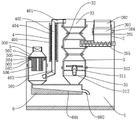
Preferably, waste heat recovery mechanism includes first trachea, third trachea, spiral trachea, water tank, first trachea one end intercommunication the heating cabinet, the other end stretch into inside the water tank, and the intercommunication spiral trachea, spiral trachea keeps away from first tracheal one end intercommunication the third trachea, the third trachea is kept away from spiral trachea's one end is stretched out the water tank, and stretches into handle incasement portion, set up like this and can replace the inside heat of spiral trachea inside burning tail gas through the inside water of water tank and come out, realized waste heat recovery utilization's function.
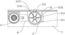
Preferably, state the air-out frame and include main tuber pipe, branch pipe, air outlet, the main tuber pipe passes through the bearing and connects the air-supply line is inboard, the welding of main tuber pipe outside has a plurality of the branch pipe, a plurality of has been seted up on the branch pipe the air outlet sets up like this and can shunts combustion-supporting gas through a plurality of air outlet, prevents that combustion-supporting gas from flowing too concentratedly, leads to blowing biomass solid fuel into first tuber pipe inside before for abundant burning, influences biomass solid fuel's abundant burning.
Preferably, the slag discharging mechanism comprises a collecting box and a slag discharging pipe, the collecting box is connected to the front end of the mounting frame through a bolt, the collecting box is hollow inside, the slag discharging pipe is welded on one side of the collecting box, so that dust in the air supply box and the dust in the processing box can be collected and collected through the collecting box in a centralized mode and removed from the slag discharging pipe, and therefore the processing of impurities is facilitated.
Preferably, the bottom plate in the collecting box is obliquely arranged, and one end of the bottom plate close to the slag discharge pipe is obliquely downward, so that the function of automatically cleaning impurities in the collecting box by utilizing gravitational potential energy is realized.
Preferably, the sintering plates are uniformly distributed below the mesh plate, so that the adsorption rate of solid particles in the combustion tail gas is increased.
Preferably, the top of the loading hopper is provided with a cover plate, so that dust can be prevented from being discharged from the loading hopper when the biomass solid fuel is crushed, and the surrounding environment is prevented from being polluted.
Has the advantages that:
1. the device can guide combustion-supporting gas into and out of the air outlet frame through the fixing frame, then the combustion-supporting gas is ejected from the air outlet frame to prevent the biomass solid fuel from falling into the deslagging mechanism before being unburned, and the combustion-supporting gas is mixed with the biomass solid fuel, so that the biomass solid fuel can be fully combusted;
2. this device can adsorb solid particle through the sintering board, has realized handling the function of the inside solid particle of burning tail gas, can also strike the otter board through burning tail gas for the sintering board vibrations make solid particle break away from the sintering board, and inside the slag extractor that falls into under the effect of gravity, realized the function of sintering board self-purification.
Additional features of the invention and advantages thereof will be set forth in the description which follows, and in part will be obvious from the description, or may be learned by practice of the invention.
Drawings
The accompanying drawings, which are included to provide a further understanding of the invention and are incorporated in and constitute a part of this specification, illustrate embodiments of the invention and together with the description serve to explain the principles of the invention and not to limit the invention. In the drawings:
FIG. 1 is a first structural schematic diagram of a combustion apparatus for biomass solid fuel according to the present invention, which has a waste heat utilization function;
FIG. 2 is a second schematic structural diagram of a combustion device for biomass solid fuel with waste heat utilization function according to the present invention;
FIG. 3 is a front view of a combustion apparatus for biomass solid fuel according to the present invention, which has a waste heat utilization function;
FIG. 4 is a top view of a combustion apparatus for biomass solid fuel according to the present invention, which has a waste heat utilization function;
FIG. 5 is a sectional view A-A of a combustion apparatus for a biomass solid fuel according to the present invention, which has a waste heat utilizing function;
FIG. 6 is a sectional view taken along line B-B of the first embodiment of the combustion apparatus for biomass solid fuel according to the present invention, which has a waste heat utilization function;
FIG. 7 is a C-C sectional view of a combustion apparatus for a biomass solid fuel according to the present invention, which has a waste heat utilizing function;
fig. 8 is a B-B sectional view of a second embodiment of a combustion apparatus for a biomass solid fuel according to the present invention, which has a waste heat utilizing function.
The reference numerals are explained below:
1. a mounting frame; 2. a crushing mechanism; 3. a combustion mechanism; 4. a waste heat recovery mechanism; 5. a dust removal mechanism; 6. a slag discharge mechanism; 201. a crushing box; 202. a hopper; 203. a crushing roller; 204. a crushing motor; 205. auger feeding equipment; 31. an air supply box; 32. a combustion box; 33. a heating box; 311. a fixed mount; 312. an air inlet pipe; 313. an air outlet frame; 3131. a main air duct; 3132. a branch pipe; 3133. an air outlet; 401. a first air pipe; 402. a second air pipe; 403. a third air pipe; 404. a spiral heat exchange tube; 405. a thermal insulation layer; 41. a helical gas pipe; 42. a water tank; 501. a treatment tank; 502. a fixed block; 503. a slide bar; 504. a spring; 505. a screen plate; 506. sintering the plate; 507. a filter screen; 508. a fan; 601. a collection box; 602. a slag discharge pipe.
Detailed Description
The technical solutions in the embodiments of the present invention will be clearly and completely described below with reference to the drawings in the embodiments of the present invention, and it is obvious that the described embodiments are only a part of the embodiments of the present invention, and not all of the embodiments.
In the description of the present invention, it is to be understood that the terms "upper", "lower", "front", "rear", "left", "right", "top", "bottom", "inner", "outer", and the like, indicate orientations or positional relationships based on the orientations or positional relationships shown in the drawings, are merely for convenience in describing the present invention and simplifying the description, and do not indicate or imply that the device or element being referred to must have a particular orientation, be constructed and operated in a particular orientation, and thus, should not be construed as limiting the present invention.
Example 1
As shown in fig. 1-7, a combustion device for biomass solid fuel with waste heat utilization function comprises an installation frame 1, a crushing mechanism 2, a waste heat recovery mechanism 4, a slag discharge mechanism 6, a combustion mechanism 3, a dust removal mechanism 5, wherein the combustion mechanism 3 comprises an air supply box 31, a combustion box 32, and a heating box 33, the air supply box 31, the combustion box 32, and the heating box 33 are connected in front of the installation frame 1 through bolts, the lower end of the air supply box 31 is communicated with the slag discharge mechanism 6, the upper end of the air supply box 31 is connected with the combustion box 32 through a flange, the top of the combustion box 32 is connected with the heating box 33 through a flange, one side of the heating box 33 is communicated with the waste heat recovery mechanism 4, the rear end of the air supply box 31 is connected with an air inlet pipe 312, one end of the air inlet pipe 312 is connected with a fixing frame 311 through bolts, in this way, combustion-supporting gas can be guided into the air inlet and outlet frame 313 through the fixing frame 311, and then the combustion-supporting gas is ejected from the air outlet frame 313 to prevent the biomass solid fuel from falling into the deslagging mechanism 6 before being unburned, and the combustion-supporting gas is mixed with the biomass solid fuel, which is beneficial to the full combustion of the biomass solid fuel, the dedusting mechanism 5 comprises a processing box 501, fixing blocks 502, sliding rods 503, springs 504, a screen plate 505, a sintering plate 506, a filter screen 507 and a fan 508, wherein the processing box 501 is connected in front of the mounting frame 1 through bolts, the fixing blocks 502 are welded at the top end of the inner wall of the processing box 501, the sliding rods 503 are welded at the tops of the fixing blocks 502, the screen plate 505 is connected outside the sliding rods 503 in a sliding manner, the springs 504 are further sleeved outside the sliding rods 503, the springs, the top of the inner side of the processing box 501 is connected with a fan 508 through a screw, the bottom of the processing box 501 extends into the slag discharging mechanism 6, so that solid particles can be adsorbed by the sintering plate 506, the function of processing the solid particles in combustion tail gas is realized, the screen plate 505 can be impacted by the combustion tail gas, the sintering plate 506 vibrates, the solid particles are separated from the sintering plate 506 and fall into the slag discharging mechanism 6 under the action of gravity, the self-cleaning function of the sintering plate 506 is realized, the crushing mechanism 2 comprises a crushing box 201, a hopper 202, crushing rollers 203, a crushing motor 204 and an auger feeding device 205, the crushing box 201 is connected to one side of the front end of the mounting frame 1 through bolts, the hopper 202 is welded to the top of the crushing box 201, two crushing rollers 203 are arranged in the crushing box 201, the two crushing rollers 203 are connected through gear engagement, and the central shaft of one crushing roller 203 extends out of the crushing box, and is connected with a crushing motor 204 through a key, the bottom of the crushing box 201 is welded with an auger feeding device 205, the discharge end of the auger feeding device 205 extends into the combustion box 32, the crushing motor 204 can drive the crushing roller 203 to rotate, thereby realizing the function of crushing biomass solid fuel, being beneficial to the full combustion of the biomass solid fuel, the number of gear teeth on the crushing roller 203 connected with the crushing motor 204 is more than that on the other crushing roller 203, the arrangement enables the rotating speeds of the two crushing rollers 203 to be different, the crushing efficiency is improved, the waste heat recovery mechanism 4 comprises a first air pipe 401, a second air pipe 402, a third air pipe 403, a spiral heat exchange pipe 404 and a heat insulation layer 405, one end of the first air pipe 401 is communicated with the heating box 33, the other end is communicated with the second air pipe 402, the spiral heat exchange pipe 404 is wound outside the second air pipe 402, the heat insulation layer, one end of the second air pipe 402 far from the first air pipe 401 is communicated with a third air pipe 403, one end of the third air pipe 403 far from the second air pipe 402 extends into the treatment box 501, the arrangement is that the heat inside the combustion tail gas inside the second air pipe 402 can be replaced through the spiral heat exchange pipe 404, and the function of waste heat recovery and utilization is realized, the air outlet frame 313 comprises a main air pipe 3131, a branch pipe 3132 and an air outlet 3133, the main air pipe 3131 is connected to the inner side of the air inlet pipe 312 through a bearing, a plurality of branch pipes 3132 are welded on the outer side of the main air pipe 3131, a plurality of air outlets 3133 are formed in the branch pipes 3132, the arrangement is that the combustion-supporting gas can be shunted through the plurality of air outlets 3133, the combustion-supporting gas is prevented from being excessively concentrated, the biomass solid fuel is blown into the first air pipe 401 before being sufficiently combusted, so, Arrange sediment pipe 602, collecting box 601 passes through bolted connection at the mounting bracket 1 front end, the inside cavity of collecting box 601, and collecting box 601 one side welding has arrange sediment pipe 602, the setting can concentrate the dust of collecting air-supply box 31 and processing case 501 inside through collecting box 601 like this, and get rid of from arranging sediment pipe 602, the processing of impurity has been made things convenient for, the bottom plate slope sets up in collecting box 601, and the one end slope that is close to arrange sediment pipe 602 is downward, the function of the inside impurity of automatic clearance collecting box 601 of gravitational potential energy has been utilized in the setting like this, sintering plate 506 evenly distributed is in otter board 505 below, the setting has increased the adsorption efficiency to the solid particle in the burning tail gas like this, loading hopper 202 top is provided with the apron, the setting can prevent when broken biomass solid fuel like this, the dust is discharged from loading hopper 202, cause the.
In the structure, when in use, firstly, the biomass solid fuel is put into the crushing box 201 through the hopper 202, at this time, the crushing motor 204 drives the crushing roller 203 to rotate, the crushing roller 203 crushes the biomass solid fuel, the crushed biomass solid fuel enters the auger feeding device 205 and finally enters the combustion box 32 to be combusted, at this time, the air inlet pipe 312 introduces combustion-supporting gas into the air outlet frame 313 and is discharged upwards through the air outlet frame 313, the combustion-supporting gas is mixed with the biomass solid fuel, so that the biomass solid fuel is fully combusted, the combusted flame enters the heating box 33, at this time, the combusted tail gas enters the first air pipe 401, when the combusted tail gas enters the second air pipe 402, the spiral heat exchange pipe 404 replaces the heat in the second air pipe 402 to realize the recovery of waste heat, the tail gas enters the treatment box 501 through the third air pipe 403, at this moment, the sintering plate 506 adsorbs solid particles, the function of treating the solid particles in the combustion tail gas is realized, the screen plate 505 can be impacted by the combustion tail gas, the sintering plate 506 vibrates, the solid particles are separated from the sintering plate 506 and fall into the slag discharging mechanism 6 under the action of gravity, the self-cleaning function of the sintering plate 506 is realized, and finally, impurities entering the collection box 601 are discharged from the slag discharging pipe 602.
Example 2
As shown in fig. 8, embodiment 2 differs from embodiment 1 in that: waste heat recovery mechanism 4 includes first trachea 401, third trachea 403, trachea 41, water tank 42, first trachea 401 one end intercommunication heating cabinet 33, the other end stretches into inside water tank 42, and intercommunication trachea 41, trachea 41 keeps away from first trachea 401's one end intercommunication third trachea 403, the one end that trachea 41 was kept away from to third trachea 403 stretches out water tank 42, and stretch into and handle the case 501 inside, set up like this and can come out the inside heat replacement of the inside burning tail gas of trachea 41 through the inside water of water tank 42, waste heat recovery utilizes's function has been realized.
In the structure, when in use, firstly, the biomass solid fuel is put into the crushing box 201 through the hopper 202, at this time, the crushing motor 204 drives the crushing roller 203 to rotate, the crushing roller 203 crushes the biomass solid fuel, the crushed biomass solid fuel enters the auger feeding device 205 and finally enters the combustion box 32 to be combusted, at this time, the air inlet pipe 312 introduces combustion-supporting gas into the air outlet frame 313 and is upwards discharged through the air outlet frame 313, the combustion-supporting gas is mixed with the biomass solid fuel, so that the biomass solid fuel is fully combusted, the combusted flame enters the heating box 33, at this time, the combusted tail gas enters the first air pipe 401, when the combusted tail gas enters the spiral air pipe 41, the heat inside the spiral air pipe 41 is replaced into the water tank 42, the recovery of waste heat is realized, the tail gas enters the processing box 501 through the third air pipe 403, at this moment, the sintering plate 506 adsorbs solid particles, the function of treating the solid particles in the combustion tail gas is realized, the screen plate 505 can be impacted by the combustion tail gas, the sintering plate 506 vibrates, the solid particles are separated from the sintering plate 506 and fall into the slag discharging mechanism 6 under the action of gravity, the self-cleaning function of the sintering plate 506 is realized, and finally, impurities entering the collection box 601 are discharged from the slag discharging pipe 602.
The foregoing illustrates and describes the principles, general features, and advantages of the present invention. It will be understood by those skilled in the art that the present invention is not limited to the embodiments described above, which are described in the specification and illustrated only to illustrate the principle of the present invention, but that various changes and modifications may be made therein without departing from the spirit and scope of the present invention, which fall within the scope of the invention as claimed. The scope of the invention is defined by the appended claims and equivalents thereof.
Claims (10)
1. The utility model provides a living beings solid fuel is with burner that has waste heat utilization function, includes mounting bracket, broken mechanism, waste heat recovery mechanism, slag extractor, its characterized in that: the waste heat recovery device further comprises a combustion mechanism and a dust removal mechanism, wherein the combustion mechanism comprises an air supply box, a combustion box and a heating box, the air supply box, the combustion box and the heating box are connected in front of the mounting frame through bolts, the lower end of the air supply box is communicated with the slag discharge mechanism, the upper end of the air supply box is connected with the combustion box through a flange, the top of the combustion box is connected with the heating box through a flange, one side of the heating box is communicated with the waste heat recovery mechanism, the rear end of the air supply box is connected with an air inlet pipe, one end of the air inlet pipe is connected with a fixing frame through bolts, an air outlet frame is arranged in the center of the top of the fixing frame, the fixing frame is connected inside the air supply box through bolts, the dust removal mechanism comprises a processing box, a fixing block, a sliding rod, handle incasement wall top welding and have a plurality of the fixed block, the welding of fixed block top has the slide bar, slide bar outside sliding connection has the otter board, the slide bar outside still cover is equipped with the spring, just the spring still is located the otter board below, there is a plurality of otter board bottom through the screw connection the sintered plate, the otter board top is provided with the filter screen, handle incasement side top and have through the screw connection the fan, it stretches into to handle the bottom of the case portion inside the sediment mechanism.
2. The combustion device with waste heat utilization function for biomass solid fuel according to claim 1, characterized in that: broken mechanism includes broken case, loading hopper, crushing roller, broken motor, auger feeder equipment, broken case passes through bolted connection and is in mounting bracket front end one side, broken roof welding has the loading hopper, broken incasement portion is provided with two the crushing roller, and two connect through gear engagement between the crushing roller, one of them the center pin of crushing roller stretches out broken case, and have through the key-type connection broken motor, the welding of broken bottom of the case portion auger feeder equipment, auger feeder equipment's discharge end stretches into inside the combustion box.
3. The combustion apparatus for biomass solid fuel with waste heat utilization function according to claim 2, characterized in that: the number of teeth on the crushing roller connected to the crushing motor is greater than the number of teeth on the other crushing roller.
4. The combustion device with waste heat utilization function for biomass solid fuel according to claim 1, characterized in that: the waste heat recovery mechanism comprises a first air pipe, a second air pipe, a third air pipe, a spiral heat exchange pipe and a heat insulation layer, one end of the first air pipe is communicated with the heating box, the other end of the first air pipe is communicated with the second air pipe, the spiral heat exchange pipe is wound on the outer side of the second air pipe, the heat insulation layer is wrapped on the outer side of the spiral heat exchange pipe, the second air pipe is far away from one end of the first air pipe is communicated with the third air pipe, and one end of the second air pipe is far into the treatment box.
5. The combustion device with waste heat utilization function for biomass solid fuel according to claim 1, characterized in that: waste heat recovery mechanism includes first trachea, third trachea, spiral trachea, water tank, first trachea one end intercommunication the heating cabinet, the other end stretch into inside the water tank, and the intercommunication spiral trachea, spiral trachea keeps away from first tracheal one end intercommunication the third trachea, the third trachea is kept away from spiral trachea's one end is stretched out the water tank, and stretches into handle incasement portion.
6. The combustion device with waste heat utilization function for biomass solid fuel according to claim 1, characterized in that: the air outlet frame comprises a main air pipe, branch pipes and air outlets, the main air pipe is connected to the inner side of the air inlet pipe through a bearing, the branch pipes are welded to the outer side of the main air pipe, and the air outlets are formed in the branch pipes.
7. The combustion device with waste heat utilization function for biomass solid fuel according to claim 1, characterized in that: the slag discharging mechanism comprises a collecting box and a slag discharging pipe, the collecting box is connected to the front end of the mounting frame through bolts, the collecting box is hollow, and the slag discharging pipe is welded on one side of the collecting box.
8. The combustion apparatus for biomass solid fuel with waste heat utilization according to claim 7, characterized in that: the bottom plate in the collecting box is obliquely arranged, and one end of the bottom plate close to the slag discharge pipe is obliquely downward.
9. The combustion device with waste heat utilization function for biomass solid fuel according to claim 1, characterized in that: the sintering plates are uniformly distributed below the screen plate.
10. The combustion apparatus for biomass solid fuel with waste heat utilization function according to claim 2, characterized in that: the top of the charging hopper is provided with a cover plate.
Priority Applications (1)
| Application Number | Priority Date | Filing Date | Title |
|---|---|---|---|
| CN202011490574.3A CN112664924A (en) | 2020-12-16 | 2020-12-16 | Biomass solid fuel is with burner that has waste heat utilization function |
Applications Claiming Priority (1)
| Application Number | Priority Date | Filing Date | Title |
|---|---|---|---|
| CN202011490574.3A CN112664924A (en) | 2020-12-16 | 2020-12-16 | Biomass solid fuel is with burner that has waste heat utilization function |
Publications (1)
| Publication Number | Publication Date |
|---|---|
| CN112664924A true CN112664924A (en) | 2021-04-16 |
Family
ID=75404272
Family Applications (1)
| Application Number | Title | Priority Date | Filing Date |
|---|---|---|---|
| CN202011490574.3A Withdrawn CN112664924A (en) | 2020-12-16 | 2020-12-16 | Biomass solid fuel is with burner that has waste heat utilization function |
Country Status (1)
| Country | Link |
|---|---|
| CN (1) | CN112664924A (en) |
Cited By (1)
| Publication number | Priority date | Publication date | Assignee | Title |
|---|---|---|---|---|
| CN113426563A (en) * | 2021-06-26 | 2021-09-24 | 黑龙江省宾州水泥有限公司 | Hot air recycling device for cement mill |
-
2020
- 2020-12-16 CN CN202011490574.3A patent/CN112664924A/en not_active Withdrawn
Cited By (2)
| Publication number | Priority date | Publication date | Assignee | Title |
|---|---|---|---|---|
| CN113426563A (en) * | 2021-06-26 | 2021-09-24 | 黑龙江省宾州水泥有限公司 | Hot air recycling device for cement mill |
| CN113426563B (en) * | 2021-06-26 | 2022-09-02 | 黑龙江省宾州水泥有限公司 | Hot air recycling device for cement mill |
Similar Documents
| Publication | Publication Date | Title |
|---|---|---|
| CN107127205A (en) | House refuse low temperature pyrogenation processing system | |
| CN112209616A (en) | High-temperature melting process and system of thermal plasma torch | |
| CN112664924A (en) | Biomass solid fuel is with burner that has waste heat utilization function | |
| CN204573999U (en) | The combustion apparatus of fuel clean combustion and emission abatement | |
| CN106082571A (en) | Low heat value mud three change processes technique and device | |
| CN206981402U (en) | House refuse low temperature pyrogenation processing system | |
| CN111998346A (en) | Garbage disposal equipment | |
| CN105987376A (en) | Combustion equipment for fuel clean combustion and emission purification | |
| CN102268297A (en) | Large-sized biomass molding fuel fixed bed gasification power generation system | |
| CN108167833A (en) | A kind of high-temperature gasification carbonizes incinerator | |
| CN108167835A (en) | A kind of innoxious refuse burning system of full intelligence | |
| CN208074955U (en) | A kind of high-temperature gasification charing incinerator | |
| CN207962656U (en) | A kind of innoxious refuse burning system of full intelligence | |
| CN208124311U (en) | Waste incinerator stokehold batcher monitoring device | |
| CN202186985U (en) | Gasification and purification system for large-scale biomass briquetting fuel fixing bed | |
| CN208124312U (en) | Garbage incinerator front roll batcher | |
| CN112355033A (en) | High-temperature melting system of thermal plasma torch | |
| CN111457395A (en) | Device for incinerating sludge by utilizing waste incineration power generation smoke | |
| CN212987221U (en) | Garbage disposal equipment | |
| CN212319733U (en) | Waste incineration system | |
| CN220724044U (en) | Self-heating pyrolysis oil production device | |
| CN213559109U (en) | High-temperature melting system of thermal plasma torch | |
| CN207962668U (en) | A kind of gas cleaning exhaust system | |
| CN220397495U (en) | Efficient combustion furnace for biomass particles and wood veneer combustion | |
| CN207962667U (en) | A kind of bucket type feed mechanism and refuse burning system |
Legal Events
| Date | Code | Title | Description |
|---|---|---|---|
| PB01 | Publication | ||
| PB01 | Publication | ||
| SE01 | Entry into force of request for substantive examination | ||
| SE01 | Entry into force of request for substantive examination | ||
| WW01 | Invention patent application withdrawn after publication | ||
| WW01 | Invention patent application withdrawn after publication |
Application publication date: 20210416 |