CN112657043A - Balloon catheter coating hole plugging tool and machining method thereof - Google Patents
Balloon catheter coating hole plugging tool and machining method thereof Download PDFInfo
- Publication number
- CN112657043A CN112657043A CN202011432330.XA CN202011432330A CN112657043A CN 112657043 A CN112657043 A CN 112657043A CN 202011432330 A CN202011432330 A CN 202011432330A CN 112657043 A CN112657043 A CN 112657043A
- Authority
- CN
- China
- Prior art keywords
- butt joint
- hole
- straightening wire
- limiting
- balloon catheter
- Prior art date
- Legal status (The legal status is an assumption and is not a legal conclusion. Google has not performed a legal analysis and makes no representation as to the accuracy of the status listed.)
- Pending
Links
Images


Abstract
The invention provides a balloon catheter coating hole plugging tool which comprises a hole plugging straightening tool, wherein the hole plugging straightening tool comprises a guide sleeve and a butt joint part butted with the guide sleeve, a hollow plugging head is arranged at one end of the guide sleeve, a butt joint cavity is arranged in the other end of the guide sleeve, the butt joint part is embedded in the butt joint cavity, and a limiting part is arranged in the butt joint cavity; a straightening wire penetrates through the plugging head; one end of the straightening wire penetrates through the blocking head and then is connected with the limiting part. The invention discloses a balloon catheter coating hole plugging tool which is convenient and fast to operate and has a plugging and straightening function.
Description
Technical Field
The invention relates to the field of production and processing, in particular to a balloon catheter coating hole plugging tool.
Background
In the prior art, cardiac catheterization is a technique of inserting a catheter from a peripheral blood vessel and delivering the catheter to the heart cavity and all over a large blood vessel to acquire information, achieve the purposes of examination and diagnosis and also perform certain treatment measures. The catheter can be sent to the right part of the heart and the pulmonary artery, can also be sent to the left part of the heart and the aorta, and can be injected with contrast medium or be used for clinical electrophysiological examination.
Catheters used in cardiac catheterization require coating of the outer surface of the catheter during manufacture, and the coating does not adhere to the inner wall of the through-hole of the catheter. In order to uniformly coat the outer surface of the catheter, the catheter needs to be straightened and the end part of the catheter needs to be plugged through a tool, so that the operation of coating the surface of the catheter is assisted.
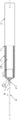
In the prior art, the tool shown in fig. 1 and 2 comprises a guide sleeve, a butt joint portion is embedded in the guide sleeve, a joint portion penetrating through the guide sleeve is arranged on the butt joint portion, and a straightening wire penetrating through the guide sleeve is welded on the joint portion. And, for the processing requirement of the pipe, the end of the pipe needs to abut against the butt joint part, and the R angle between the end of the butt joint part and the straightening wire is required to be 0 or equal to 0. Therefore, the end of the butt-joint portion and the straightening wire are not easily welded directly.
When the tool in the prior art is used for production, the tool also has the following defects:
first, the straightening wires are butt-jointed and then welded to the joint portions, although a combined connection can be achieved. However, the welding process may be deviated, and the straightening wire may not be positioned on the same line as the center of the joint portion.
Secondly, the welding spot at the joint of the straightening wire and the joining part can influence the sleeved guide sleeve, and the guide sleeve is easily damaged.
Thirdly, because the straightening wire and the connecting part are welded and overlapped at the later stage, the straightening wire is easy to break in the long-term stress production and use process, thereby influencing the production yield of the conduit.
Fourthly, the straightening wire is broken when in use, so that the straightening wire is not convenient to be lapped with the connecting part again, and particularly the connecting part is broken in a bending way, so that the straightening wire is not convenient to replace operation.
Disclosure of Invention
The invention overcomes the defects of the prior art and provides the balloon catheter coating hole plugging tool which is convenient and fast to operate and has the plugging and straightening functions.
In order to achieve the purpose, the invention adopts the technical scheme that: the hole plugging and straightening tool for the coating of the balloon catheter comprises a hole plugging and straightening tool, wherein the hole plugging and straightening tool comprises a guide sleeve and a butt joint part butted with the guide sleeve, a hollow plugging head is arranged at one end of the guide sleeve, a butt joint cavity is arranged in the other end of the guide sleeve, the butt joint part is embedded in the butt joint cavity, and a limiting part is arranged in the butt joint cavity; a straightening wire penetrates through the plugging head; one end of the straightening wire penetrates through the blocking head and then is connected with the limiting part.
In a preferred embodiment of the present invention, an elastic member for elastically abutting is disposed between the limiting portion and the abutting portion.
In a preferred embodiment of the present invention, a receiving groove for receiving the limiting portion is disposed in one side of the docking cavity close to the blocking head.
In a preferred embodiment of the present invention, a first through hole for passing through the straightening wire is formed in the limiting portion, and the center of the first through hole and the center of the second through hole of the plugging head are on the same straight line.
In a preferred embodiment of the invention, one end of the straightening wire sequentially penetrates through the second through hole and the first through hole from the outside and then is provided with a limiting block for limiting and locking.
In a preferred embodiment of the invention, the plugging head adopts a frustum structure matched and butted with the shape of the conduit, and the two through holes longitudinally penetrate through the center of the frustum structure.
In a preferred embodiment of the present invention, the position-limiting part is a sphere, and the receiving groove is matched with the shape of the sphere.
In a preferred embodiment of the invention, one end of the straightening wire sequentially penetrates through the second through hole and the first through hole of the limiting part from the outside and is welded and cured into the limiting block.
In a preferred embodiment of the invention, one end of the butt joint cavity close to the blocking head is a limiting cavity, one end of the butt joint cavity far away from the blocking head is a guiding cavity, the inner diameter of the guiding cavity is larger than that of the limiting cavity, and an inclined guiding inclined plane is arranged at one end of the joint of the limiting cavity and the guiding cavity.
In a preferred embodiment of the invention, a balloon catheter coating hole plugging tool according to any one of claims 1 to 8 is adopted to perform a catheter plugging correction processing method;
step one, assembling a straightening wire; a straightening wire penetrates through the blocking head, one end of the straightening wire penetrates through the guide pipe, the other end of the straightening wire penetrates through the second through hole of the blocking head and the first through hole of the limiting part and then is limited by the limiting block,
and secondly, positioning and limiting the limiting part, arranging the limiting part connected with the straightening wire in a containing groove in the butt joint cavity, embedding the elastic piece into the butt joint cavity to abut against the limiting part, abutting the butt joint part into the butt joint cavity to abut against the elastic piece, and elastically locking and abutting against the limiting part.
And thirdly, the plugging head abuts against the end part of the catheter, and the straightening wire vertically guides and limits the catheter on the straightening wire and the plugging head through the catheter.
In a preferred embodiment of the present invention, the elastic member is a spring, one end of the spring abuts against the limiting portion, and the other end of the spring abuts against the abutting portion fixedly embedded in the abutting cavity.
The invention solves the defects existing in the technical background, and has the beneficial technical effects that:
firstly, adopt butt joint portion and guide pin bushing butt joint combination to realize the convenient cartridge of frock, adopt the structure of independent spacing portion and stopper to realize the convenient equipment to the straightening wire simultaneously, reduced the potential safety hazard of using simultaneously. The locating point is arranged in the guide sleeve, so that the using influence on the straightening wire outside the guide sleeve is reduced, and the damage to the sleeved catheter caused by the locating connecting point is prevented.
Secondly, through wearing to establish the one end of spacing portion with the straightening silk and passing through the stopper spacing, promote the installation convenience. The limiting part and the accommodating groove are combined and positioned, so that the positioning is facilitated. The limiting block is formed by welding, heating and melting one end penetrating through the limiting part and then solidifying the end, and the convenience of installation is improved.
Thirdly, an elastic piece is arranged between the butting part and the limiting part in the guide sleeve, so that limiting locking of the limiting part is further promoted.
Drawings
The invention is further illustrated with reference to the following figures and examples.
FIG. 1 is a schematic diagram of a prior art configuration;
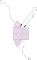
FIG. 2 is an enlarged schematic view of portion B of FIG. 1 according to the prior art;
FIG. 3 is a schematic structural diagram of a preferred embodiment of the present invention;
FIG. 4 is an enlarged view of the portion C of FIG. 3 according to the present invention;
the meaning of the reference numerals in the figures; 1-hole plugging straightening tool, 11-butt joint part, 111-butt joint head, 112-butt joint part, 12-guide sleeve, 121-butt joint cavity, 122-accommodating groove, 13-blocking head, 131-through hole II, 2-straightening wire, 21-welding zone, 3-limiting part, 31-limiting block, 5-elastic part, X-X' -central axis and 6-R angle.
Detailed Description
The invention will now be described in further detail with reference to the accompanying drawings and examples, which are simplified schematic drawings and illustrate only the basic structure of the invention in a schematic manner, and thus show only the constituents relevant to the invention.
It should be noted that, if directional indications (such as up, down, bottom, top, etc.) are involved in the embodiment of the present invention, the directional indications are only used for explaining the relative position relationship, motion situation, etc. of each component in a certain posture, and if the certain posture is changed, the directional indications are changed accordingly. The terms "first", "second" and "first" are used for descriptive purposes only and are not to be construed as indicating or implying relative importance or implicitly indicating the number of technical features indicated. Thus, a feature defined as "first" or "second" may explicitly or implicitly include one or more of that feature. Unless expressly stated or limited otherwise, the terms "disposed," "connected," and "connected" are intended to be inclusive and mean, for example, that there may be a fixed connection, a removable connection, or an integral connection; they may be connected directly or indirectly through intervening media, or they may be interconnected between two elements. The specific meanings of the above terms in the present invention can be understood in specific cases to those skilled in the art.
Example one
As shown in fig. 3 and 4, a balloon catheter coating hole plugging tool comprises a hole plugging straightening tool 1, wherein the hole plugging straightening tool 1 comprises a guide sleeve 12, a butt joint part 11 in butt joint with the guide sleeve 12 and a straightening wire 2 penetrating through the guide sleeve 12, a workpiece is sleeved on the straightening wire 2, which is positioned outside the guide sleeve 12, of the straightening wire 2, and the workpiece is a catheter used in a cardiac catheter operation.
Specifically, one end of the guide sleeve 12 is provided with a blocking head 13, the blocking head 13 is provided with a second through hole 131 which penetrates through the blocking head, the blocking head 13 adopts a frustum structure which is matched and butted with the shape of the catheter, and the second through hole 131 longitudinally penetrates through the center of the frustum structure. A butt joint cavity 121 is arranged in the other end of the guide sleeve 12, the butt joint cavity 121 is communicated with a second through hole 131 of the plugging head 13, and the second through hole 131 and the butt joint cavity 121 are combined to penetrate through the guide sleeve 12.
The one end that the butt joint chamber 121 is close to shutoff head 13 is spacing chamber, and the one end that the shutoff head 13 was kept away from to butt joint chamber 121 is the direction chamber, and the internal diameter in direction chamber is greater than the internal diameter in spacing chamber, and just spacing chamber is provided with the tilting direction inclined plane that inwards gradually shrinks with direction chamber junction one end. One side of the limiting cavity of the abutting cavity 121 close to the blocking head 13 is provided with a receiving groove 122. A guide groove is formed in one side, far away from the plugging head 13, of the butt joint cavity 121, so that the butt joint cavity can be conveniently in guide butt joint with the butt joint part 11. The receiving groove 122 movably receives the stopper portion 3 therein. The limiting part 3 is provided with a first through hole for penetrating the straightening wire 2, and the first through hole and the center of the second through hole 131 of the plugging head 13 are on the same straight line. The limiting part 3 is a sphere, and the accommodating groove 122 is matched with the sphere in shape. And a first through hole for the straightening wire 2 to pass through is arranged in the sphere in a penetrating way. Further, the ball body is made of stainless steel balls.
Specifically, the butt joint part 11 is embedded in the butt joint cavity 121 of the guide sleeve 12. One end of the abutting part 11 is provided with an abutting joint 111 embedded into the abutting cavity 121, the abutting joint 111 is movably embedded into the abutting cavity 121, and the abutting joint 111 is matched with the abutting cavity 121 in shape. Further, the docking portion 11 is screwed with the docking cavity 121. But not limited thereto, other combination connection structures in the prior art can be adopted in other embodiments. The end of the abutment 111 faces the receiving groove 122 and defines the stopper 3 in the abutment cavity 121 between the abutment 111 and the receiving groove 122. An elastic piece 5 used for elastic abutting is arranged between the limiting part 3 and the abutting part 11, and the elastic piece 5 is a spring in the prior art. And the outer diameter of the spring is smaller than the outer diameter of the butting part 11, and the inner diameter of the spring is larger than the inner diameter of the first through hole of the butting part 11.
Specifically, a straightening wire 2 is arranged in the plugging head 13 in a penetrating manner; one end of the straightening wire 2 is inserted into the plugging head 13 and then connected with the limiting part 3. More specifically, one end of the straightening wire 2 is provided with a limiting block 31 for limiting and locking after passing through the second through hole 131 and the first through hole in sequence from the outside.
One end of the straightening wire 2 penetrates through the second through hole 131 of the plugging head 13 and the first through hole of the limiting part 3 from the outside in sequence and then is welded and solidified into the limiting block 31. The straightening wire 2 is a nickel-titanium alloy wire made of nickel-titanium alloy.
Example two
A balloon catheter coating hole plugging tool is adopted, and a catheter plugging correction processing method is adopted;
step one, assembling a straightening wire 2; the inside of the plugging head 13 is provided with a straightening wire 2 in a penetrating way, one end of the straightening wire 2 penetrates through the guide pipe, the other end of the straightening wire 2 penetrates through a second through hole 131 of the plugging head 13 and is limited by a limiting block 31 after being positioned in a first through hole of the limiting part 3 of the butt joint cavity 121.
And secondly, positioning and limiting the limiting part 3, arranging the limiting part 3 connected with the straightening wire 2 in the accommodating groove 122 in the butt joint cavity 121, embedding the elastic piece 5 into the butt joint cavity 121 to abut against the limiting part 3, abutting the butt joint part 11 into the butt joint cavity 121 to abut against the elastic piece 5, and elastically locking to abut against the limiting part 3. The elastic element 5 is a spring, one end of the spring abuts against the limiting part 3, and the other end of the spring abuts against the abutting part 11 fixedly embedded in the abutting cavity 121.
And step three, the plugging head 13 abuts against the end part of the catheter, and the straightening wire 2 vertically guides and limits the catheter on the straightening wire 2 and the plugging head 13 through the catheter.
The working principle of the invention is as follows:
as shown in fig. 3 and 4, in use, one end of the straightening wire 2 penetrates through the guide tube, the other end of the straightening wire 2 penetrates through the second through hole 131 of the plugging head 13 and the first through hole of the limiting part 3 in the butt joint cavity 121, and then the end of the straightening wire 2 is welded by laser welding and solidified into the limiting block 31 for locking and limiting.
The abutment 11 is pressed into the abutment cavity 121 against the spring which locks against the stop 3. One end of the spring abuts against the steel ball, and the other end of the spring abuts against the abutting part 11 fixedly embedded in the abutting cavity 121. The steel ball with the wire 2 attached thereto is confined in the housing groove 122. The plugging head 13 is abutted against the end part of the catheter, and the straightening wire 2 penetrates through the catheter to vertically guide and limit the catheter on the straightening wire 2 and the plugging head 13.
The above embodiments are specific supports for the idea of the present invention, and the protection scope of the present invention is not limited thereby, and any equivalent changes or equivalent modifications made on the basis of the technical scheme according to the technical idea of the present invention still belong to the protection scope of the technical scheme of the present invention.
Claims (10)
1. The utility model provides a sacculus pipe coating plug hole frock, includes plug hole aligning frock, plug hole aligning frock includes the guide pin bushing and with the butt joint portion of guide pin bushing butt joint, the one end of guide pin bushing is provided with the shutoff head of well expert, be provided with the butt joint chamber in the other end of guide pin bushing, the butt joint intracavity inlays and is equipped with butt joint portion, its characterized in that: a limiting part is arranged in the butt joint cavity; a straightening wire penetrates through the plugging head; one end of the straightening wire penetrates through the blocking head and then is connected with the limiting part.
2. The balloon catheter coating hole plugging tool according to claim 1, wherein: an elastic piece used for elastic abutting is arranged between the limiting part and the butt joint part.
3. The balloon catheter coating hole plugging tool according to claim 1, wherein: and one side of the butt joint cavity close to the blocking head is provided with a containing groove for containing the limiting part.
4. The balloon catheter coating hole plugging tool according to claim 3, wherein: the limiting portion is provided with a first through hole used for penetrating the straightening wire, and the center of the first through hole and the center of the second through hole of the plugging head are on the same straight line.
5. The balloon catheter coating hole plugging tool according to claim 4, wherein: one end of the straightening wire sequentially penetrates through the second through hole and the first through hole from the outside and is provided with a limiting block for limiting and locking.
6. The balloon catheter coating hole plugging tool according to claim 5, wherein: the plug head adopts a frustum structure matched and butted with the shape of the conduit, and the through hole II longitudinally penetrates through the center of the frustum structure.
7. The balloon catheter coating hole plugging tool according to claim 6, wherein: the limiting part is a sphere, and the accommodating groove is matched with the sphere in shape.
8. The balloon catheter coating hole plugging tool according to claim 4 or 7, wherein: one end of the straightening wire sequentially penetrates through the second through hole and the first through hole of the limiting part from the outside and is welded and solidified into the limiting block.
9. The processing method of the balloon catheter coating hole plugging tool is characterized by comprising the following steps of: a balloon catheter coating hole plugging tool according to any one of claims 1-8 is adopted, and a catheter plugging correction processing method is adopted;
step one, assembling a straightening wire; a straightening wire penetrates through the blocking head, one end of the straightening wire penetrates through the guide pipe, the other end of the straightening wire penetrates through the second through hole of the blocking head and the first through hole of the limiting part and then is limited by the limiting block,
positioning and limiting a limiting part, arranging the limiting part connected with the straightening wire in a receiving groove in the butt joint cavity, embedding the elastic piece into the butt joint cavity to abut against the limiting part, abutting the butt joint part into the butt joint cavity to abut against the elastic piece, and elastically locking the elastic piece to abut against the limiting part;
and thirdly, the plugging head abuts against the end part of the catheter, and the straightening wire vertically guides and limits the catheter on the straightening wire and the plugging head through the catheter.
10. The processing method of the balloon catheter coating hole plugging tool according to claim 9, characterized by comprising the following steps: the elastic piece is a spring, one end of the spring abuts against the limiting part, and the other end of the spring abuts against the butt joint part fixedly embedded in the butt joint cavity.
Priority Applications (1)
| Application Number | Priority Date | Filing Date | Title |
|---|---|---|---|
| CN202011432330.XA CN112657043A (en) | 2020-12-10 | 2020-12-10 | Balloon catheter coating hole plugging tool and machining method thereof |
Applications Claiming Priority (1)
| Application Number | Priority Date | Filing Date | Title |
|---|---|---|---|
| CN202011432330.XA CN112657043A (en) | 2020-12-10 | 2020-12-10 | Balloon catheter coating hole plugging tool and machining method thereof |
Publications (1)
| Publication Number | Publication Date |
|---|---|
| CN112657043A true CN112657043A (en) | 2021-04-16 |
Family
ID=75401716
Family Applications (1)
| Application Number | Title | Priority Date | Filing Date |
|---|---|---|---|
| CN202011432330.XA Pending CN112657043A (en) | 2020-12-10 | 2020-12-10 | Balloon catheter coating hole plugging tool and machining method thereof |
Country Status (1)
| Country | Link |
|---|---|
| CN (1) | CN112657043A (en) |
Citations (7)
| Publication number | Priority date | Publication date | Assignee | Title |
|---|---|---|---|---|
| JP2001204824A (en) * | 2000-01-31 | 2001-07-31 | Terumo Corp | Catheter straitening device and catheter assembly |
| JP2003325659A (en) * | 2002-05-10 | 2003-11-18 | Hakko Medical:Kk | Drainage apparatus for laparoscopic operation |
| US20110092892A1 (en) * | 2008-04-08 | 2011-04-21 | Jetprep Ltd. | Body passage cleansing device |
| TW201436868A (en) * | 2013-01-04 | 2014-10-01 | Fishman Corp | Catheter tip coating system |
| CN207887666U (en) * | 2018-03-05 | 2018-09-21 | 繁昌县华特机械制造有限公司 | A kind of pipe straightener structure |
| CN211412606U (en) * | 2019-11-04 | 2020-09-04 | 上海加奇生物科技苏州有限公司 | Hole plugging device for medical catheter |
| CN215608666U (en) * | 2020-12-10 | 2022-01-25 | 昆山名威精密工业有限公司 | Sacculus pipe coating hole blocking tool |
-
2020
- 2020-12-10 CN CN202011432330.XA patent/CN112657043A/en active Pending
Patent Citations (7)
| Publication number | Priority date | Publication date | Assignee | Title |
|---|---|---|---|---|
| JP2001204824A (en) * | 2000-01-31 | 2001-07-31 | Terumo Corp | Catheter straitening device and catheter assembly |
| JP2003325659A (en) * | 2002-05-10 | 2003-11-18 | Hakko Medical:Kk | Drainage apparatus for laparoscopic operation |
| US20110092892A1 (en) * | 2008-04-08 | 2011-04-21 | Jetprep Ltd. | Body passage cleansing device |
| TW201436868A (en) * | 2013-01-04 | 2014-10-01 | Fishman Corp | Catheter tip coating system |
| CN207887666U (en) * | 2018-03-05 | 2018-09-21 | 繁昌县华特机械制造有限公司 | A kind of pipe straightener structure |
| CN211412606U (en) * | 2019-11-04 | 2020-09-04 | 上海加奇生物科技苏州有限公司 | Hole plugging device for medical catheter |
| CN215608666U (en) * | 2020-12-10 | 2022-01-25 | 昆山名威精密工业有限公司 | Sacculus pipe coating hole blocking tool |
Similar Documents
| Publication | Publication Date | Title |
|---|---|---|
| US10856988B2 (en) | Self-aligning radiopaque ring | |
| CN215608666U (en) | Sacculus pipe coating hole blocking tool | |
| JP4681551B2 (en) | Guide wire for catheter | |
| US20140207153A1 (en) | Delivery system, method, and anchor for medical implant placement | |
| US20170065251A1 (en) | System and Method for Measuring Fluidics in Arteries | |
| US20060184165A1 (en) | Irrigated tip catheter and method for manufacturing therefor | |
| WO2017143457A4 (en) | Imaging probe with rotatable core | |
| US20220175256A1 (en) | Guidewire with internal pressure sensor | |
| CN112657043A (en) | Balloon catheter coating hole plugging tool and machining method thereof | |
| JP2023512862A (en) | A guidewire with a radiopaque inner coil | |
| EP3969096A1 (en) | Pressure sensing guidewires, systems and methods for structural heart procedures | |
| JP5108580B2 (en) | Indwelling needle | |
| CN105796093B (en) | Central venous catheter external member | |
| JP2023511808A (en) | Dimpled joint for guide wire | |
| JP2018524086A (en) | Intravascular devices, systems and methods using molded ribbons attached with adhesives | |
| JP2016093289A (en) | Medical stylet | |
| JP6550726B2 (en) | Balloon catheter | |
| CN220237540U (en) | Welding-free high-performance nickel-titanium memory alloy and stainless steel composite micro-guide wire | |
| CN115055771B (en) | Guide wire with high safety performance and high operability and welding method | |
| EP3315160B1 (en) | Apparatus including multiple joined hypotubes and method of making same | |
| CN213489552U (en) | Medical catheter | |
| US20220265193A1 (en) | ECG Stylet with Improved Fatigue and Break Resistance | |
| CN211835745U (en) | Guide wire | |
| CN219183646U (en) | Slotted endoscope adapter ring | |
| CN112074317B (en) | Catheter and medical device for introducing therapeutic solution |
Legal Events
| Date | Code | Title | Description |
|---|---|---|---|
| PB01 | Publication | ||
| PB01 | Publication | ||
| SE01 | Entry into force of request for substantive examination | ||
| SE01 | Entry into force of request for substantive examination |