CN112647256B - Intelligent clothes hanger - Google Patents
Intelligent clothes hanger Download PDFInfo
- Publication number
- CN112647256B CN112647256B CN202011284514.6A CN202011284514A CN112647256B CN 112647256 B CN112647256 B CN 112647256B CN 202011284514 A CN202011284514 A CN 202011284514A CN 112647256 B CN112647256 B CN 112647256B
- Authority
- CN
- China
- Prior art keywords
- sliding
- clothes
- groove
- chute
- locking
- Prior art date
- Legal status (The legal status is an assumption and is not a legal conclusion. Google has not performed a legal analysis and makes no representation as to the accuracy of the status listed.)
- Active
Links
Images


Classifications
-
- D—TEXTILES; PAPER
- D06—TREATMENT OF TEXTILES OR THE LIKE; LAUNDERING; FLEXIBLE MATERIALS NOT OTHERWISE PROVIDED FOR
- D06F—LAUNDERING, DRYING, IRONING, PRESSING OR FOLDING TEXTILE ARTICLES
- D06F57/00—Supporting means, other than simple clothes-lines, for linen or garments to be dried or aired
- D06F57/12—Supporting means, other than simple clothes-lines, for linen or garments to be dried or aired specially adapted for attachment to walls, ceilings, stoves, or other structures or objects
- D06F57/125—Supporting means, other than simple clothes-lines, for linen or garments to be dried or aired specially adapted for attachment to walls, ceilings, stoves, or other structures or objects for attachment to, or close to, the ceiling
-
- Y—GENERAL TAGGING OF NEW TECHNOLOGICAL DEVELOPMENTS; GENERAL TAGGING OF CROSS-SECTIONAL TECHNOLOGIES SPANNING OVER SEVERAL SECTIONS OF THE IPC; TECHNICAL SUBJECTS COVERED BY FORMER USPC CROSS-REFERENCE ART COLLECTIONS [XRACs] AND DIGESTS
- Y02—TECHNOLOGIES OR APPLICATIONS FOR MITIGATION OR ADAPTATION AGAINST CLIMATE CHANGE
- Y02B—CLIMATE CHANGE MITIGATION TECHNOLOGIES RELATED TO BUILDINGS, e.g. HOUSING, HOUSE APPLIANCES OR RELATED END-USER APPLICATIONS
- Y02B40/00—Technologies aiming at improving the efficiency of home appliances, e.g. induction cooking or efficient technologies for refrigerators, freezers or dish washers
- Y02B40/18—Technologies aiming at improving the efficiency of home appliances, e.g. induction cooking or efficient technologies for refrigerators, freezers or dish washers using renewables, e.g. solar cooking stoves, furnaces or solar heating
Landscapes
- Engineering & Computer Science (AREA)
- Textile Engineering (AREA)
- Holders For Apparel And Elements Relating To Apparel (AREA)
Abstract
The invention relates to an intelligent clothes hanger, which pushes a clothes-horse out of a window or pulls the clothes-horse back to the room through a pushing device arranged on an indoor ceiling, wherein the window is an automatic sliding window driven by a gear rack; a rain and wind sensor is arranged on the clothes airing support, and when rain and strong wind are sensed, a signal is transmitted to the pushing device to drive the clothes airing rod to be retracted indoors and the sliding window is automatically closed; the clothes hanger realizes automatic clothes airing, solves the problem that the clothes cannot be retracted in time in rainy days, is reliable in mechanism and good in airing effect, and is suitable for being popularized in the market comprehensively.
Description
Technical Field
The invention relates to the technical field of clothes airing devices, in particular to an intelligent clothes hanger.
Background
In the real life, people adopt the mode of stoving or sunning to the clothes of washing to carry out the drying to the clothes, and chinese generally adopts the mode of sunning to carry out the drying, if: and hanging the washed clothes on a clothes hanger on an open balcony for airing, placing the clothes on a clothes hanger below a building for airing, and collecting the clothes after the clothes are aired. The mode of adopting the sunning is energy-conserving not only, but also can carry out effectual disinfecting to the clothes, but the balcony is a comparatively confined space, ventilation is relatively poor, it is not good that the clothes carries out the effect of drying of sunning at the balcony, the clothes is great outdoor the limitation of carrying out the sunning, need timely when the weather sudden change collect the clothes, people work busy or business outside, can't be timely when the weather sudden change collect the clothes, especially the south of china, the weather in summer is changeable, the time that is fit for the sunning clothes is short and the dispersion, consequently, it is thick at a great deal of defect and inconvenience at outdoor sunning clothes, in addition work is tired, the affair is entangled and is leaded to forgetting to collect the clothes also common thing. The clothes hanger has two categories of hand-operated clothes hanger and remote control clothes hanger at present, the structure style is single, airing and clothes collection need to be finished manually on site, the automation degree is low, trouble and labor are wasted, along with the improvement of modern living standard, a brand-new intelligent clothes hanger capable of automatically sensing weather conditions is urgently needed, and the function of automatically sending clothes to the outside of a window in fine days and timely collecting the clothes in rainy or windy days is realized.
Disclosure of Invention
In order to solve the problems, the invention provides an intelligent clothes hanger.
The technical scheme of the invention is as follows: an intelligent clothes hanger that dries in air which characterized in that: the clothes hanger comprises a clothes-horse pushing device, an automatic sliding window and a plurality of clothes-horses;
the clothes airing rod pushing device comprises a lead screw support, a lead screw sleeved with a nut sliding block and a transverse push-pull rod, wherein the lead screw support is fixed in the middle of an indoor ceiling and at a position corresponding to a window;
the automatic sliding window comprises an inner window sash and an outer window sash which are connected in a window frame in a sliding mode, wherein an inner rack is fixed on the upper end face of the inner window sash, an outer rack corresponding to teeth and the inner rack is fixed on the upper end face of the outer window frame, gears which are respectively meshed with the inner rack and the outer rack are arranged between the inner rack and the outer rack, a motor is arranged in the middle of an upper frame of the motor window frame, and a shaft of the motor penetrates through the upper frame and is coaxially and fixedly connected with the gears; the upper end of the window frame is outwards provided with a clothes drying support, the outer end of the clothes drying support is provided with a plurality of locking devices B which have the same structure as the locking devices A and are in one-to-one correspondence with the locking devices A, two sides of the window frame are provided with sliding rails A corresponding to the locking devices B in position through vertical supporting rods, and the outer end part of the clothes drying support is provided with a rainwater and wind sensor;
the clothes-horse is connected with the sliding rail A in a sliding mode through the sliding groove A arranged in the middle of the bottom surface along the length direction, and two ends of the clothes-horse can be locked with the locking devices A or the locking devices B on two sides.
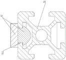
Preferably, the lower frame of the window frame is provided with two parallel sliding grooves B along the length direction, and the bottom surfaces of the inner sash and the outer sash are respectively provided with a sliding rail B along the length direction to be sleeved in the two sliding grooves B to form a sliding connection structure.
Preferably, the locking device A is fixedly connected with the transverse push-pull rod through a groove-shaped plate, and the locking device A is fixedly connected with the clothes drying support through a groove-shaped plate.
Preferably, two sides of the middle part of the upper frame of the window frame are respectively provided with a window sash limiting plate which is in sliding contact with the side surfaces of the inner window sash and the outer window sash downwards.
Preferably, the locking device A or the locking device B comprises a square shell with an opening at the upper end, a locking mechanism and a T-shaped locking head, the locking mechanism comprises a positioning sliding block and a positioning sliding rod which are connected in the square shell in a sliding manner, a guide post is arranged in a notch arranged on one side of the positioning sliding block along the length direction, a spring with the lower end supported on the lower end plate of the shell is sleeved on the guide post, a sliding chute A with the gradually rising chute bottom is arranged on the right side of the positioning sliding block upwards, a sliding chute B with the gradually rising chute bottom is arranged on the left side of the positioning sliding block downwards, the lower end of the sliding chute A is intersected with the lower end of the sliding chute B, a lower arc-shaped chute is arranged at the intersection, and the lower end of the sliding chute B is higher than the lower end of the sliding chute A; the upper end of the right side of the positioning sliding block is provided with a chute C which is inclined downwards, the upper end of the chute C is communicated with the upper end of the chute A, the upper end of the left side of the positioning sliding block is provided with a chute D which is inclined downwards, the upper end of the chute D is communicated with the upper end of the chute B, the lower end of the chute C is intersected with the lower end of the chute D, an upper arc-shaped groove is arranged at the intersection, the groove bottom of the chute C is lower than the groove bottom of the upper end of the chute A, and the groove bottom of the chute D is lower than the groove bottom of the chute C and higher than the groove bottom of the upper end of the chute B;
the lower end of the positioning slide rod is hinged to the middle of the lower short plate of the square shell, and the upper end of the positioning slide rod is downwards provided with a slide column capable of sliding in each slide groove;
articulated through vertical axisymmetric on the bottom plate that location slider upper end set up have two locking hooks, vertical epaxial being equipped with can be with the outside torsional spring that bounces open of locking hook, the inside coupler body in locking hook upper end is equipped with the half circular groove, the centre of bottom plate is equipped with the roof pressure boss that is located between two locking hooks, the size of the first intermediate junction post of T shape locking and the size phase-match in half circular groove, the size of the spheroidal size of T shape locking head lower extreme and the interval between two locking hooks match, T shape locking head of equal fixedly connected with in clothes-horse's both ends.
Preferably, the two sides of the upper opening of the square shell are respectively provided with a circular groove-shaped boss, and a rolling shaft is rotatably connected in the two circular groove-shaped bosses.
Preferably, the inner surface of the cover plate of the square shell is provided with a pressure spring, and the pressure spring is pressed in the middle of the positioning slide rod in the square shell.
The beneficial technical effects of the invention are as follows:
the intelligent clothes hanger pushes the clothes airing rod out of a window or pulls the clothes airing rod back to the room through a pushing device arranged on an indoor ceiling, the window is an automatic sliding window driven by a gear rack, when the clothes airing rod extends out of the window from the room to dry clothes, the gear drives two racks to slide two window sashes inwards, the window is opened, the clothes airing rod extends out of the window to dry the clothes, corresponding locking devices are arranged on a clothes airing support and a transverse push-pull rod, and the continuous clothes airing rod can be locked or unlocked through T-shaped locking heads at two ends of the continuous clothes airing rod and the two locking devices, so that the automatic fixation of the clothes airing rod is realized;
a rain and wind sensor is arranged on the clothes airing support, when rain or strong wind is sensed, a signal is transmitted to the pushing device to drive the clothes airing rod to be retracted into a room, and the sliding window is automatically closed; the clothes hanger realizes automatic clothes airing, solves the problem that the clothes cannot be retracted in time in rainy or windy days, is reliable in mechanism and good in airing effect, and is suitable for being popularized in the market comprehensively.
Drawings
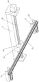
FIG. 1 is a schematic perspective view of the present invention;
FIG. 2 is a sectional view taken along line B-B of FIG. 1;
fig. 3 is a schematic perspective structure view of the clothes-horse pushing device of the present invention;
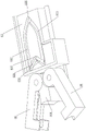
FIG. 4 is a schematic top view of the clothes-horse of the present invention extended out of the window and locked by the T-shaped locking head and the locking device B;
FIG. 5 is a schematic top view of the clothes-horse of the present invention (with the upper frame hidden) after extending out of the window and being locked by the T-shaped locking head and the locking device B;
fig. 6 is a schematic top view of the clothes-horse of the present invention (with the upper frame hidden) retracted indoors and locked by the T-shaped locking head and the locking device b a on the pushing device;
FIG. 7 is a sectional view taken along line A-A in FIG. 6;
FIG. 8 is a cross-sectional view taken along line C-C of FIG. 7;
figure 9 is a schematic view of the structure of the clothes airing rod and the T-shaped locking head of the invention;
FIG. 10 is a schematic perspective view of the locking device of the present invention;
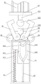
figure 11 is a schematic view of the clothes drying pole of the present invention about to be locked by the locking means;
FIG. 12 is a schematic structural view of the T-shaped locking head on the clothes-horse of the present invention pressing down the pressing boss and locked by the locking device;
FIG. 13 is a schematic structural view of the T-shaped locking head on the clothes-horse of the present invention pressing down the pressing boss to unlock the locking device;
FIG. 14 is a schematic view of the internal perspective of the locking device of the present invention;
FIG. 15 is a schematic perspective view of a positioning block according to the present invention;
FIG. 16 is a second schematic perspective view of the positioning block of the present invention;
fig. 17 is a perspective view of the cover plate of the locking device of the present invention.
In the drawing, 01, a clothes airing rod pushing device, 11, a lead screw support, 12, a nut slide block, 13, a lead screw, 131, a limiting slide plate, 14, a transverse push-pull rod, 15, a lead screw motor, 16, a locking device A, 21, an inner window sash, 211, an inner rack, 22, an outer window sash, 221, an outer rack, 222, a sliding rail B, 23, a gear, 24, a motor, 03, a window frame, 31, an upper frame, 311, a window sash limiting plate, 32, a lower frame, 321, a sliding groove B, 41, a vertical supporting rod, 42, a sliding rail A, 51, a clothes airing rod, 511, a sliding groove A, 61, a clothes airing support, 611, a rain sensor, 612, a locking device B, 613, a wind sensor, 71, a groove plate, 81, a square shell, 811, a cover plate, 812, a pressure spring, 82. T-shaped locking head, 821, a connecting column, 822, a sphere, 83, a positioning slide block, 831, a guide column, 832, a sliding groove A, 834, a third chute, a fourth chute, a fifth chute, a sixth, a fourth chute, a sixth, a fourth, a, 835. The sliding groove T, 836, a lower arc groove, 837, an upper arc groove, 838, a jacking boss, 84, a positioning sliding rod, 841, a sliding column, 85, a spring, 86, a locking hook, 861, a semi-circular groove, 87, a torsion spring and 88, a rolling shaft.
Detailed Description
Embodiment one, refer to fig. 1-17 in the description, an intelligent clothes hanger that dries in air, its characterized in that: an intelligent clothes hanger comprises a clothes hanger pushing device, an automatic sliding window and a plurality of clothes hangers;
the clothes airing rod pushing device comprises a lead screw support, a lead screw sleeved with a nut sliding block and a transverse push-pull rod, wherein the lead screw support is fixed in the middle of an indoor ceiling and at a position corresponding to a window;
the automatic sliding window comprises an inner window sash and an outer window sash which are connected in a window frame in a sliding mode, an inner rack is fixed on the upper end face of the inner window sash, teeth and an outer rack corresponding to the inner rack are fixed on the upper end face of the outer window frame, gears which are respectively meshed with the inner rack and the outer rack are arranged between the inner rack and the outer rack, the inner rack and the outer rack on two sides can be driven to move linearly in opposite directions by the rotation of the gears, the window sash below the rack is driven to open or close the window, a motor is arranged in the middle of an upper frame of a motor window frame, and a shaft of the motor penetrates through the upper frame and a gear shaft of the gear to be coaxially and fixedly connected; the upper end of the window frame is outwards provided with a clothes drying support, the outer end of the clothes drying support is provided with a plurality of locking devices B which have the same structure as the locking devices A and are in one-to-one correspondence with the locking devices A, two sides of the window frame are provided with sliding rails A corresponding to the locking devices B in position through vertical supporting rods, a clothes drying rod slides out of a window or slides into the window along the sliding rails A, the outer end of the clothes drying support is provided with a rainwater sensor and a wind sensor, and when rainwater falls onto the rainwater sensor or strong wind is blown, the rainwater sensor or the wind sensor can transmit a signal of raining or strong wind to a clothes drying rod pushing device;
the locking device A or the locking device B comprises a square shell with an opening at the upper end, a locking mechanism and a T-shaped locking head, wherein the locking mechanism comprises a positioning sliding block and a positioning sliding rod which are connected in the square shell in a sliding manner, a guide post is arranged in a notch arranged on one side of the positioning sliding block along the length direction, a spring with the lower end supported on the lower end plate of the shell is sleeved on the guide post, a sliding groove A with the gradually rising groove bottom is arranged on the right side of the positioning sliding block upwards, a sliding groove B with the gradually rising groove bottom is arranged on the left side of the positioning sliding block downwards, the lower end of the sliding groove A is intersected with the lower end of the sliding groove B, a lower arc-shaped groove is arranged at the intersection, and the lower end of the sliding groove B is higher than the lower end of the sliding groove A; the upper end of the right side of the positioning sliding block is provided with a chute C which is inclined downwards, the upper end of the chute C is communicated with the upper end of the chute A, the upper end of the left side of the positioning sliding block is provided with a chute D which is inclined downwards, the upper end of the chute D is communicated with the upper end of the chute B, the lower end of the chute C is intersected with the lower end of the chute D, an upper arc-shaped groove is arranged at the intersection, the groove bottom of the chute C is lower than the groove bottom of the upper end of the chute A, and the groove bottom of the chute D is lower than the groove bottom of the chute C and higher than the groove bottom of the upper end of the chute B;
the lower end of the positioning slide rod is hinged to the middle of the lower short plate of the square shell, and the upper end of the positioning slide rod is downwards provided with a slide column capable of sliding in each slide groove; and a pressure spring is arranged on the inner surface of the cover plate of the square shell and pressed in the middle of the positioning slide rod in the square shell.
The clothes airing rod is characterized in that two locking hooks are symmetrically hinged to a bottom plate arranged at the upper end of a positioning sliding block through a vertical shaft, a torsion spring capable of bouncing the locking hooks outwards is arranged on the vertical shaft, a semicircular groove is formed in a hook body inward at the upper end of each locking hook, a jacking boss located between the two locking hooks is arranged in the middle of the bottom plate, the size of a connecting column in the middle of the T-shaped locking head is matched with that of the semicircular groove, the semicircular groove is used for locking a connecting column in the middle of the T-shaped locking head, the size of a ball at the lower end of the T-shaped locking head is matched with that of the space between the two locking hooks, and two ends of the clothes airing rod are fixedly connected with a T-shaped locking head; the two sides of the upper opening of the square shell are respectively provided with a circular groove-shaped boss, and a rolling shaft is rotatably connected in the two circular groove-shaped bosses.
The principle of the locking device is as follows:
when locking the T-shaped locking head
The T-shaped locking head presses the jacking boss at the upper end inwards from between the two locking hooks, the positioning sliding block slides inwards in the shell, the two locking hooks rotate oppositely under the action of the rolling shaft and enter the shell, the sliding column of the positioning sliding rod slides upwards along the sliding groove A relative to the positioning sliding block, after the sliding column slides out of the upper end of the sliding groove A and enters the sliding groove C, the positioning sliding block slides upwards under the action of the spring, the sliding column slides downwards along the sliding groove C relative to the positioning sliding block and enters the upper arc-shaped groove and is fixed, at the moment, the upper ends of the two locking hooks are closed, and the ball body of the T-shaped locking head is locked between the two locking hooks;
when the lock is released
And the T-shaped locking head is pressed inwards again, the sliding column of the positioning sliding rod slides upwards along the sliding groove T and slides out of the sliding groove T to enter the sliding groove B, at the moment, under the action of the spring, the sliding column of the positioning sliding rod moves downwards relative to the positioning sliding block along the sliding groove B, meanwhile, the two locking hooks stretch out of the shell and rotate reversely, after the sliding column of the positioning sliding rod enters the lower arc-shaped groove C along the sliding groove B and is fixed, the two locking hooks stretch out of the shell completely and push the T-shaped locking head out of the shell, and the locking of the T-shaped locking head is released.
The clothes-horse is connected with the sliding rail A in a sliding mode through the sliding groove A arranged in the middle of the bottom surface along the length direction, and two ends of the clothes-horse can be locked with the locking devices A or the locking devices B on two sides.
The lower frame of the window frame is provided with two parallel sliding chutes B along the length direction, and the bottom surfaces of the inner sash and the outer sash are both provided with sliding rails B along the length direction and sleeved in the two sliding chutes B to form a sliding connection structure; the window frame is characterized in that window sash limiting plates which are in sliding contact with the side faces of the inner window sash and the outer window sash are respectively arranged on two sides of the middle of the upper frame of the window frame downwards, and the sliding rail sliding groove arranged at the lower end of the window and the window sash limiting plate arranged at the upper end ensure the stability of the window during sliding left and right and are not prone to failure.
The locking device A is fixedly connected with the transverse push-pull rod through the trough plate, and the locking device A is fixedly connected with the clothes drying support through the trough plate.
The working process and principle of the invention are as follows:
when drying clothes
The clothes are hung on a clothes airing rod, a lead screw of a pushing device drives a transverse push-pull rod at the lower end of a nut sliding block to move outwards, the clothes airing rod locked on the transverse push-pull rod moves outwards along a sliding rail A, when the clothes airing rod is close to an automatic sliding window, a gear rack drives two window sashes to slide in opposite directions to open the window, the clothes airing rod continues to move and extends out of the window, a T-shaped locking head at the outer end of the clothes airing rod is pressed into a locking device B on a clothes airing support after extending out of the window to be locked, the clothes airing rod is fixed, at the moment, the locking device A on the transverse push-pull rod and the T-shaped locking head at the inner end of the clothes airing rod can be unlocked according to the method, the pushing device moves inwards to be far away from the automatic sliding window, and the automatic sliding window is closed;
in rainy or windy conditions
The automatic sliding window is opened, the pushing device moves outwards and the T-shaped locking head at the inner end of the clothes airing rod is locked, then the clothes airing rod is continuously pushed outwards, the T-shaped locking head at the outer end of the clothes airing rod and the locking device B on the clothes airing support are unlocked, the pushing device moves inwards and drives the clothes airing rod hung with clothes to return to the indoor space, and the automatic sliding window is closed.
Claims (6)
1. An intelligent clothes hanger that dries in air which its characterized in that: the clothes hanger comprises a clothes-horse pushing device, an automatic sliding window and a plurality of clothes-horses;
the clothes airing rod pushing device comprises a lead screw support, a lead screw sleeved with a nut sliding block and a transverse push-pull rod, wherein the lead screw support is fixed in the middle of an indoor ceiling and at a position corresponding to a window;
the automatic sliding window comprises an inner window sash and an outer window sash which are connected in a window frame in a sliding manner, wherein an inner rack is fixed on the upper end surface of the inner window sash, teeth and an outer rack corresponding to the inner rack are fixed on the upper end surface of the outer window frame, gears which are respectively meshed with the inner rack and the outer rack are arranged between the inner rack and the outer rack, a motor is arranged in the middle of an upper frame of the motor window frame, and a shaft of the motor penetrates through the upper frame and is coaxially and fixedly connected with the gears; the upper end of the window frame is outwards provided with a clothes drying support, the outer end of the clothes drying support is provided with a plurality of locking devices B which have the same structure as the locking devices A and are in one-to-one correspondence with the locking devices A, two sides of the window frame are provided with sliding rails A corresponding to the locking devices B in position through vertical supporting rods, and the outer end part of the clothes drying support is provided with a rainwater and wind sensor;
the clothes airing rod is connected with the sliding rail A in a sliding mode through a sliding groove A formed in the middle of the bottom surface in the length direction, and two ends of the clothes airing rod can be locked with the locking devices A or the locking devices B on two sides;
the locking device A or the locking device B comprises a square shell with an opening at the upper end, a locking mechanism and a T-shaped locking head, wherein the locking mechanism comprises a positioning sliding block and a positioning sliding rod which are connected in the square shell in a sliding manner, a guide post is arranged in a notch arranged on one side of the positioning sliding block along the length direction, a spring with the lower end supported on the lower end plate of the shell is sleeved on the guide post, a sliding groove A with the gradually rising groove bottom is arranged on the right side of the positioning sliding block upwards, a sliding groove B with the gradually rising groove bottom is arranged on the left side of the positioning sliding block downwards, the lower end of the sliding groove A is intersected with the lower end of the sliding groove B, a lower arc-shaped groove is arranged at the intersection, and the lower end of the sliding groove B is higher than the lower end of the sliding groove A; the upper end of the right side of the positioning sliding block is provided with a chute C which is inclined downwards, the upper end of the chute C is communicated with the upper end of the chute A, the upper end of the left side of the positioning sliding block is provided with a chute D which is inclined downwards, the upper end of the chute D is communicated with the upper end of the chute B, the lower end of the chute C is intersected with the lower end of the chute D, an upper arc-shaped groove is arranged at the intersection, the groove bottom of the chute C is lower than the groove bottom of the upper end of the chute A, and the groove bottom of the chute D is lower than the groove bottom of the chute C and higher than the groove bottom of the upper end of the chute B; the lower end of the positioning slide rod is hinged to the middle of the lower short plate of the square shell, and the upper end of the positioning slide rod is downwards provided with a slide column capable of sliding in each slide groove; articulated through vertical axisymmetric on the bottom plate that location slider upper end set up have two locking hooks, vertical epaxial being equipped with can outwards be bounced open the torsional spring with the locking hook, the internal semicircular groove that is equipped with of locking hook upper end inward coupler, the centre of bottom plate is equipped with the roof pressure boss that is located between two locking hooks, the size of T shape locking head intermediate junction post and the size phase-match in semicircular groove, the spheroidal size of T shape locking head lower extreme and the size of the interval between two locking hooks match, the equal fixedly connected with T shape locking head in clothes-horse's both ends.
2. The intelligent laundry rack of claim 1, wherein: the lower frame of the window frame is provided with two parallel sliding grooves B along the length direction, and the bottom surfaces of the inner sash and the outer sash are respectively provided with a sliding rail B along the length direction to be sleeved in the two sliding grooves B to form a sliding connection structure.
3. The intelligent laundry rack of claim 1, characterized in that: the locking device A is fixedly connected with the transverse push-pull rod through the trough plate, and the locking device A is fixedly connected with the clothes drying support through the trough plate.
4. The intelligent laundry rack of claim 1, wherein: and window sash limiting plates which are in sliding contact with the side surfaces of the inner window sash and the outer window sash are respectively arranged downwards on two sides of the middle part of the upper frame of the window frame.
5. The intelligent laundry rack of claim 1, wherein: the two sides of the upper end opening of the square shell are respectively provided with a circular groove-shaped boss, and a rolling shaft is rotatably connected in the two circular groove-shaped bosses.
6. The intelligent laundry rack of claim 1, wherein: and a pressure spring is arranged on the inner surface of the cover plate of the square shell and pressed in the middle of the positioning slide rod in the square shell.
Priority Applications (1)
| Application Number | Priority Date | Filing Date | Title |
|---|---|---|---|
| CN202011284514.6A CN112647256B (en) | 2020-11-17 | 2020-11-17 | Intelligent clothes hanger |
Applications Claiming Priority (1)
| Application Number | Priority Date | Filing Date | Title |
|---|---|---|---|
| CN202011284514.6A CN112647256B (en) | 2020-11-17 | 2020-11-17 | Intelligent clothes hanger |
Publications (2)
| Publication Number | Publication Date |
|---|---|
| CN112647256A CN112647256A (en) | 2021-04-13 |
| CN112647256B true CN112647256B (en) | 2022-06-03 |
Family
ID=75349735
Family Applications (1)
| Application Number | Title | Priority Date | Filing Date |
|---|---|---|---|
| CN202011284514.6A Active CN112647256B (en) | 2020-11-17 | 2020-11-17 | Intelligent clothes hanger |
Country Status (1)
| Country | Link |
|---|---|
| CN (1) | CN112647256B (en) |
Families Citing this family (1)
| Publication number | Priority date | Publication date | Assignee | Title |
|---|---|---|---|---|
| CN113914079B (en) * | 2021-10-22 | 2023-05-26 | 中国地质大学(武汉) | Device capable of automatically collecting and airing clothes |
Citations (11)
| Publication number | Priority date | Publication date | Assignee | Title |
|---|---|---|---|---|
| GB9011426D0 (en) * | 1990-04-04 | 1990-07-11 | Kwan Cheung W | Mobile arrangement for airing clothes |
| CN2682098Y (en) * | 2003-12-26 | 2005-03-02 | 宋志峰 | Outdoor rainproof clothes airing device |
| CN202544623U (en) * | 2012-05-05 | 2012-11-21 | 胡佳威 | Multifunctional intelligent window |
| CN203782443U (en) * | 2014-04-01 | 2014-08-20 | 湖州师范学院 | Anti-theft laundry rack capable of automatically opening and closing window and sensing wind and rain |
| CN104631068A (en) * | 2015-02-06 | 2015-05-20 | 上海海事大学 | Intelligent laundry rack based on open balcony |
| KR20150066667A (en) * | 2013-12-07 | 2015-06-17 | 박상원 | Smart Drying Rack |
| KR101656215B1 (en) * | 2015-06-10 | 2016-09-09 | 함태석 | Clothes for the laundry veranda window sill |
| CN107201854A (en) * | 2016-03-18 | 2017-09-26 | 袁燎 | A kind of rifle lock firm in structure |
| CN110886072A (en) * | 2019-12-03 | 2020-03-17 | 浙江工业职业技术学院 | Intelligent clothes hanger |
| CN211498207U (en) * | 2019-07-13 | 2020-09-15 | 平湖市职业中学 | Intelligent balcony capable of automatically retracting clothes hanger based on temperature and humidity |
| CN111719296A (en) * | 2020-06-05 | 2020-09-29 | 南通大学 | Intelligent indoor and outdoor clothes hanger |
Family Cites Families (6)
| Publication number | Priority date | Publication date | Assignee | Title |
|---|---|---|---|---|
| JP2658977B2 (en) * | 1995-06-12 | 1997-09-30 | 株式会社クリーン企画 | Outdoor curtain equipment |
| CN201048816Y (en) * | 2007-06-29 | 2008-04-23 | 江门市第一职业高级中学 | Automatic airing clothes-hanger |
| KR101256645B1 (en) * | 2013-01-29 | 2013-04-19 | 임노경 | Window locking apparatus with drying rack |
| CN204939916U (en) * | 2015-08-19 | 2016-01-06 | 神龙电气有限公司 | The lock position limiting mechanism of switch for door enclosure of washing machine |
| CN107268246A (en) * | 2017-07-26 | 2017-10-20 | 陈可勋 | Balcony automatically dries in the air clothing system |
| CN110005313B (en) * | 2019-05-07 | 2019-11-26 | 桐乡市易尔顺科技信息咨询有限公司 | A kind of window |
-
2020
- 2020-11-17 CN CN202011284514.6A patent/CN112647256B/en active Active
Patent Citations (12)
| Publication number | Priority date | Publication date | Assignee | Title |
|---|---|---|---|---|
| GB9011426D0 (en) * | 1990-04-04 | 1990-07-11 | Kwan Cheung W | Mobile arrangement for airing clothes |
| CN2069875U (en) * | 1990-04-04 | 1991-01-23 | 张伟君 | Guide-type movable airer |
| CN2682098Y (en) * | 2003-12-26 | 2005-03-02 | 宋志峰 | Outdoor rainproof clothes airing device |
| CN202544623U (en) * | 2012-05-05 | 2012-11-21 | 胡佳威 | Multifunctional intelligent window |
| KR20150066667A (en) * | 2013-12-07 | 2015-06-17 | 박상원 | Smart Drying Rack |
| CN203782443U (en) * | 2014-04-01 | 2014-08-20 | 湖州师范学院 | Anti-theft laundry rack capable of automatically opening and closing window and sensing wind and rain |
| CN104631068A (en) * | 2015-02-06 | 2015-05-20 | 上海海事大学 | Intelligent laundry rack based on open balcony |
| KR101656215B1 (en) * | 2015-06-10 | 2016-09-09 | 함태석 | Clothes for the laundry veranda window sill |
| CN107201854A (en) * | 2016-03-18 | 2017-09-26 | 袁燎 | A kind of rifle lock firm in structure |
| CN211498207U (en) * | 2019-07-13 | 2020-09-15 | 平湖市职业中学 | Intelligent balcony capable of automatically retracting clothes hanger based on temperature and humidity |
| CN110886072A (en) * | 2019-12-03 | 2020-03-17 | 浙江工业职业技术学院 | Intelligent clothes hanger |
| CN111719296A (en) * | 2020-06-05 | 2020-09-29 | 南通大学 | Intelligent indoor and outdoor clothes hanger |
Also Published As
| Publication number | Publication date |
|---|---|
| CN112647256A (en) | 2021-04-13 |
Similar Documents
| Publication | Publication Date | Title |
|---|---|---|
| CN203782443U (en) | Anti-theft laundry rack capable of automatically opening and closing window and sensing wind and rain | |
| CN112647256B (en) | Intelligent clothes hanger | |
| CN110397367B (en) | Automatic opening and closing window for building in rainy days | |
| CN108708142B (en) | Convenient outdoor clothes hanger that dries in air of type based on thing networking | |
| CN113622533A (en) | Waterproof sound-proof wall of environmental protection for building | |
| CN111188168A (en) | Automatic clothes hanger | |
| CN205585231U (en) | Device dries in air at tealeaves stand | |
| CN211081457U (en) | Induction type self-closing intelligent window | |
| CN212958201U (en) | Rainwater-sensing automatic-closing intelligent silent door and window | |
| CN109402979B (en) | Indoor and outdoor dual-purpose clothes hanger | |
| CN212027507U (en) | Novel rain-proof window of clothing is received to intelligence | |
| CN205936127U (en) | Domestic dustproof automatic control window | |
| CN111679587A (en) | Intelligent home system based on Internet of things | |
| CN207854617U (en) | A kind of windbreak for green house of vegetables | |
| CN220266114U (en) | Clothes hanger for balcony | |
| CN205474473U (en) | Clothes hanger | |
| CN216256327U (en) | Intelligence house is with intelligent sofa of taking dust absorption function | |
| CN221461931U (en) | Intelligent airing room | |
| CN215978116U (en) | Sliding type roof electric window opener | |
| CN112359563B (en) | Intelligent clothes hanger | |
| CN214655849U (en) | Intelligent clothes hanger with multiple functions | |
| CN215070932U (en) | Davit control machine case with rain-proof structure | |
| CN221129569U (en) | Novel curtain box | |
| CN2641252Y (en) | Rail type horizontal rotating, pushing and slanting open window | |
| CN221078189U (en) | Civil engineering construction raise dust on-line sampling check out test set |
Legal Events
| Date | Code | Title | Description |
|---|---|---|---|
| PB01 | Publication | ||
| PB01 | Publication | ||
| SE01 | Entry into force of request for substantive examination | ||
| SE01 | Entry into force of request for substantive examination | ||
| GR01 | Patent grant | ||
| GR01 | Patent grant |