CN112548475A - Intelligent tool clamp for welding mechanical parts - Google Patents
Intelligent tool clamp for welding mechanical parts Download PDFInfo
- Publication number
- CN112548475A CN112548475A CN202011403971.2A CN202011403971A CN112548475A CN 112548475 A CN112548475 A CN 112548475A CN 202011403971 A CN202011403971 A CN 202011403971A CN 112548475 A CN112548475 A CN 112548475A
- Authority
- CN
- China
- Prior art keywords
- shaft
- adjusting frame
- seat
- groove
- welding
- Prior art date
- Legal status (The legal status is an assumption and is not a legal conclusion. Google has not performed a legal analysis and makes no representation as to the accuracy of the status listed.)
- Withdrawn
Links
Images


Classifications
-
- B—PERFORMING OPERATIONS; TRANSPORTING
- B23—MACHINE TOOLS; METAL-WORKING NOT OTHERWISE PROVIDED FOR
- B23K—SOLDERING OR UNSOLDERING; WELDING; CLADDING OR PLATING BY SOLDERING OR WELDING; CUTTING BY APPLYING HEAT LOCALLY, e.g. FLAME CUTTING; WORKING BY LASER BEAM
- B23K37/00—Auxiliary devices or processes, not specially adapted to a procedure covered by only one of the preceding main groups
- B23K37/04—Auxiliary devices or processes, not specially adapted to a procedure covered by only one of the preceding main groups for holding or positioning work
- B23K37/047—Auxiliary devices or processes, not specially adapted to a procedure covered by only one of the preceding main groups for holding or positioning work moving work to adjust its position between soldering, welding or cutting steps
Abstract
The invention discloses an intelligent tool clamp for welding mechanical parts, which comprises a lifting seat, a rectangular adjusting frame, an adjusting gear, a bearing shaft, a first pin shaft, a second pin shaft, a groove-shaped seat and a tool plate. According to the invention, a lifting seat, a rectangular adjusting frame and a bearing shaft penetrating through the rectangular adjusting frame are arranged, the bearing shaft and the rectangular adjusting frame are in vertical rotating fit, the top of the rectangular adjusting frame is connected with the top of a base sleeve on the lifting seat through a first bolt, the height of the first bolt is higher than that of the rotary axis of the bearing shaft, the rotary plane of the bearing shaft is superposed with the axis of the first bolt, the other end of the bearing shaft is connected with a tooling plate, when the welding gravity center is inclined, the lifting of the gravity center is controlled by controlling the rotation of the bearing shaft, the gravity center is superposed with the axis of the first pin shaft, the gravity center is adjusted completely, and the first pin shaft is conveniently used as a rotating shaft to rotate stably.
Description
Technical Field
The invention relates to the technical field of tool clamps for welding, in particular to an intelligent tool clamp for welding mechanical parts.
Background
The welding part in the mechanical field is mainly an assembly part, the assembly part usually comprises a base part and a plurality of accessories, the base part is a reference part, a tool fixture is used for fixing the reference part and the accessories during combined welding, the overall welding is carried out after the fixing is finished, and for some overall welded structures, the turnover welding is needed, so that the welding tool during turnover appears on the market, but the tool is large in limitation, particularly, the rotation of the same type of part can be controlled to be balanced, the turnover of the same type of part is usually unbalanced when the accessories are added at different welding stages or different welding parts are switched, namely, the turnover gravity center deviates from the rotation axis, and the turnover welding is inconvenient; the complex adjustment operation of this type of frock structure is wasted time and energy, and the operation is inconvenient moreover.
Therefore, the invention provides an intelligent tool clamp for welding mechanical parts.
Disclosure of Invention
The invention aims to: in order to solve the problems mentioned in the background art, the intelligent tool clamp for welding the mechanical parts is provided.
In order to achieve the purpose, the invention adopts the following technical scheme:
an intelligent tool clamp for welding mechanical parts comprises a lifting seat, a rectangular adjusting frame, an adjusting gear, a bearing shaft, a first pin shaft, a second pin shaft, a groove-shaped seat and a tool plate, wherein the outer wall of a base sleeve of the lifting seat is connected with a fixed block through a supporting plate, the fixed block is positioned above an action shaft of the lifting seat, the rectangular adjusting frame is positioned on one side of the lifting seat, the top of the rectangular adjusting frame is detachably connected with the fixed block through the first pin shaft, the first pin shaft is horizontally distributed, the outer wall of the bearing shaft is hinged with the rectangular adjusting frame, the height of a hinged joint is lower than that of the first pin shaft, the rotating plane of the bearing shaft is a vertical plane and is superposed with the axis of the first pin shaft, a semicircular gear ring is fixedly arranged in the rectangular adjusting frame, the axis of the semicircular gear ring is superposed with the rotating axis of the bearing shaft, a abdicating hole matched with the semicircular gear ring, the adjusting gear rotates and sets up in the hole of stepping down and with semicircle ring gear external toothing, and this adjusting gear's shaft stretches out to outside and fixed connection accommodate motor, bear a weight of axle one end and rotate and be connected with the connecting axle, the one end of this connecting axle can be dismantled through round pin axle two and cell type seat and be connected, the top sliding fit of cell type seat for horizontal distribution and bottom and action axle, the connecting axle uses round pin axle two to be horizontal distribution after in the entering cell type seat as the pivot.
As a further description of the above technical solution:
the top of the rectangular adjusting frame is fixedly provided with an upper connecting plate, the upper connecting plate penetrates through the bearing sleeve in a sleeved mode, the fixing block is provided with a first insertion hole, and the first pin shaft is matched with the bearing sleeve and the first insertion hole in use.
As a further description of the above technical solution:
the top of the action shaft is fixedly provided with a sliding seat, the top of the sliding seat is provided with a sliding groove in sliding fit with the groove-shaped seat, the opening of the groove-shaped seat faces upwards, two vertical plates which are distributed in parallel are provided with a second insertion hole, the outer wall of the connecting shaft is provided with a third insertion hole in a penetrating mode, and the second insertion hole and the third insertion hole are matched with the second pin shaft for use.
As a further description of the above technical solution:
the bottom of rectangle adjusting frame is fixed to be provided with down the connecting plate, run through on the lower connecting plate and close soon and prop the axle, the one end of propping the axle uses with the cooperation of one side of base cover.
As a further description of the above technical solution:
and the other end of the supporting shaft is fixedly provided with a rotating handle.
As a further description of the above technical solution:
and two side walls in the groove-shaped seat are fixedly provided with limiting blocks matched with the connecting shaft for use.
In summary, due to the adoption of the technical scheme, the invention has the beneficial effects that:
1. according to the invention, a lifting seat, a rectangular adjusting frame and a bearing shaft penetrating through the rectangular adjusting frame are arranged, the bearing shaft and the rectangular adjusting frame are in vertical rotating fit, the top of the rectangular adjusting frame is connected with the top of a base sleeve on the lifting seat through a first bolt, the height of the first bolt is higher than that of the rotary axis of the bearing shaft, the rotary plane of the bearing shaft is superposed with the axis of the first bolt, the other end of the bearing shaft is connected with a tooling plate, when the welding gravity center is inclined, the lifting of the gravity center is controlled by controlling the rotation of the bearing shaft, the gravity center is superposed with the axis of the first pin shaft, the gravity center is adjusted completely, and the first pin shaft is conveniently used as a rotating shaft to rotate stably.
2. According to the invention, one end of the bearing shaft is rotatably provided with the connecting shaft, the connecting shaft is detachably connected with the groove-shaped seat which is arranged on the lifting seat in a sliding manner through the bolt II and the groove-shaped seat which is arranged on the top of the action shaft on the lifting seat, so that the bearing shaft can passively rotate to a horizontal position after the center of gravity is adjusted by removing the pin I, the tool plate can be stably overturned in a balanced manner by taking the pin II as a rotating shaft, and the tool plate and workpieces thereon can be in the horizontal position, so that the welding after.
3. In the invention, the bottom of the rectangular adjusting frame is fixedly provided with the lower connecting plate, the lower connecting plate is penetrated and screwed with the supporting shaft, one end of the supporting shaft is matched with one side of the base sleeve for use, the other end of the supporting shaft is fixedly provided with the rotating handle, and the supporting shaft can be rotated to enable one end of the supporting shaft to be pressed against one side of the base sleeve, so that the first pin shaft and the second pin shaft can be conveniently disassembled and assembled, the operation is convenient, and labor is saved.
Drawings
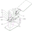
FIG. 1 is a schematic structural diagram of the overall assembly of an intelligent tool clamp for welding mechanical parts according to the present invention;
FIG. 2 is a schematic structural diagram of an intelligent tool clamp for welding mechanical parts shown in the front view of FIG. 1;
FIG. 3 is a schematic structural diagram of connection of a rectangular adjusting frame, a first pin shaft and a base sleeve in FIG. 1 of the intelligent tool clamp for welding mechanical parts, provided by the invention;
FIG. 4 is a schematic structural view of a rectangular adjusting frame, an adjusting gear, an adjusting motor and a bearing shaft in FIG. 1 of the intelligent tool clamp for welding mechanical parts, which is provided by the invention;
fig. 5 is a schematic structural view of the intelligent tool clamp for welding mechanical parts, which is provided by the invention, showing the matching structure of the bearing shaft, the second pin shaft, the groove-shaped seat and the rectangular adjusting frame in fig. 1.
Illustration of the drawings:
1. a lifting seat; 11. a base sleeve; 111. a support plate; 1111. a fixed block; 11111. a first jack; 12. an action shaft; 121. a slide base; 1211. a chute; 2. a rectangular adjusting frame; 21. a semicircular gear ring; 22. an upper connecting plate; 221. a bearing sleeve; 23. a lower connecting plate; 231. a supporting shaft; 2311. turning a handle; 3. an adjusting gear; 31. a wheel axle; 4. a load bearing shaft; 41. a hole of abdication; 42. a connecting shaft; 5. a first pin shaft; 6. a second pin shaft; 7. a trough-shaped seat; 71. a vertical plate; 711. a second jack; 72. a limiting block; 8. assembling a plate; 9. the motor is regulated.
Detailed Description
The technical solutions in the embodiments of the present invention will be clearly and completely described below with reference to the drawings in the embodiments of the present invention, and it is obvious that the described embodiments are only a part of the embodiments of the present invention, and not all of the embodiments. All other embodiments, which can be derived by a person skilled in the art from the embodiments given herein without making any creative effort, shall fall within the protection scope of the present invention.
Example 1
Referring to fig. 1-5, an intelligent tooling fixture for welding mechanical parts comprises a lifting seat 1, a rectangular adjusting frame 2, an adjusting gear 3, a bearing shaft 4, a first pin 5, a second pin 6, a groove-shaped seat 7 and a tooling plate 8, wherein the tooling plate 8 is used for positioning a workpiece, other parts are used for adjusting the rotating gravity center of the tooling plate 8 and the workpiece carried by the tooling plate 8, so that the workpiece can be freely turned over, the outer wall of a base sleeve 11 of the lifting seat 1 is connected with a fixing block 1111 through a support plate 111, the fixing block 1111 is positioned above an action shaft 12 of the lifting seat 1, the rectangular adjusting frame 2 is positioned at one side of the lifting seat 1, the top of the rectangular adjusting frame 2 is detachably connected with the fixing block 1111 through a first pin 5, namely the whole rectangular adjusting frame 2 can be separated from the fixing block 1111 after the first pin 5 is pulled out, the first pin 5 is horizontally distributed, and the first pin 5 is, specifically, an upper connecting plate 22 is fixedly arranged at the top of the rectangular adjusting frame 2, the upper connecting plate 22 is sleeved with a bearing sleeve 221 in a penetrating manner, a first insertion hole 11111 is formed in the fixing block 1111, and a first pin 5 is matched with the bearing sleeve 221 and the first insertion hole 11111 for use; the outer surface wall of the bearing shaft 4 is hinged with the rectangular adjusting frame 2, the height of a hinged point is lower than that of the first pin shaft 5, the rotating plane of the bearing shaft 4 is a vertical plane and is overlapped with the axis of the first pin shaft 5, the bearing shaft 4 can be horizontally distributed at the initial adjustment stage, the other end of the bearing shaft 4 is connected with one end of the tooling plate 8, and the gravity center formed by the rectangular adjusting frame 2, parts in the rectangular adjusting frame, the tooling plate 8 and workpieces on the rectangular adjusting frame is located below the axis of the first pin shaft 5; a semicircular gear ring 21 is fixedly arranged in the rectangular adjusting frame 2, the axis of the semicircular gear ring 21 is overlapped with the rotation axis of the bearing shaft 4, a yielding hole 41 matched with the semicircular gear ring 21 for use is formed in the bearing shaft 4, the adjusting gear 3 is rotatably arranged in the yielding hole 41 and is meshed with the semicircular gear ring 21, the wheel shaft 31 of the adjusting gear 3 extends out to the outside and is fixedly connected with an adjusting motor 9, therefore, the bearing shaft 4 can be driven to rotate around a hinge point by controlling the rotation of the adjusting gear 3, the tooling plate 8 is controlled to ascend and be in an inclined position, the height of the gravity center ascends and is positioned or approximately positioned on the axis of the pin shaft I5, the tooling plate 8 can be easily turned over at the moment, the front and back of a workpiece can be conveniently converted, but the tooling plate 8 is in the inclined position at the moment; one end of the bearing shaft 4 is rotatably connected with a connecting shaft 42, the connecting shaft 42 and the bearing shaft 4 are coaxially distributed at the moment, one end of the connecting shaft 42 is detachably connected with a groove-shaped seat 7 through a pin shaft II 6, the bearing shaft 4 is in an inclined position at the initial stage of gravity center adjustment, the connecting shaft 42 is also in an inclined position at the moment, the groove-shaped seat 7 is horizontally distributed, the bottom of the groove-shaped seat 7 is in sliding fit with the top of the action shaft 12, specifically, a sliding seat 121 is fixedly arranged at the top of the action shaft 12, a sliding groove 1211 in sliding fit with the groove-shaped seat 7 is formed at the top of the sliding seat 121, a second inserting hole 711 is formed in the groove-shaped seat 7 with an upward opening, two vertical plates 71 which are distributed in parallel are provided with the opening, a third inserting hole is formed in the outer wall of the connecting shaft 42 in a penetrating manner, the, from this control lift seat 1 goes up and down, make the highly convenient jack three on through round pin axle two 6 and connecting axle 42 of slot type seat 7 connect, hydraulic cylinder formula elevating system can be chooseed for use to lift seat 1, after slot type seat 7 and connecting axle 42 are connected, can manual lifting frock board 8, and take off round pin axle one 5, then below frock board 8, both sides wall in the slot type seat 7 is fixed to be provided with stopper 72 with connecting axle 42 cooperation use, and then connecting axle 42 can get into between two stoppers 72 and be in the horizontal distribution, because the focus that the aforesaid was adjusted is equally on the axis of connecting axle 42, consequently, with connecting axle 42 as the pivot can rotatory frock board 8, frock board 8 can not incline, and then conveniently adjust the back two-sided welding, wholly have the intelligent regulation function, the adjustment is swift.
Example 2
Referring to fig. 5, in embodiment 1, the lifting action of the tooling plate 8 is involved, and in order to further facilitate the operation, the difference between this embodiment and embodiment 1 is that a lower connecting plate 23 is fixedly disposed at the bottom of the rectangular adjusting frame 2, a supporting shaft 231 is screwed on the lower connecting plate 23, one end of the supporting shaft 231 is used in cooperation with one side of the base sleeve 11, a rotating handle 2311 is fixedly disposed at the other end of the supporting shaft 231, and the supporting shaft 231 can be rotated to enable one end of the supporting shaft 231 to be pressed against one side of the base sleeve 11, so that the first pin shaft 5 and the second pin shaft 6 can be conveniently disassembled and assembled, and further, the operation is convenient and labor-saving.
The working principle is as follows: when the adjustable lifting seat is used, the lifting seat 1 is fixed on the ground, the adjusting motor 9 is electrically connected with an external control electric box, the control electric box provides electric energy, a workpiece to be welded is fixed on the tooling plate 8 through the clamping device, the center of gravity formed by the tooling plate 8, the workpiece, accessories on the tooling plate 8, the whole rectangular adjusting frame 2 and components in the whole rectangular adjusting frame 2 is positioned below the axis of the pin shaft I5, the adjusting motor 9 is controlled to rotate and drive the adjusting gear 3 to rotate, then the bearing shaft 4 rotates under the action of the semicircular gear ring 21, the tooling plate 8 rises, the center of gravity rises similarly, the pin shaft II 6 is in a taken-down state in the overshoot, the adjusting degree is judged by judging the swinging resistance of the rectangular adjusting frame 2 by taking the pin shaft I5 as a rotating shaft, after the adjustment, the center of gravity is positioned on the axis of the pin shaft I5, and at the moment, the action shaft 12 on the lifting seat 1 is controlled to rise, then the groove-shaped seat 7 is slid to conveniently connect the pin shaft II 6 with the groove-shaped seat 7 and the connecting shaft 42, then the supporting shaft 231 is rotated to enable one end of the supporting shaft 231 to be pressed against the side wall of the base sleeve 11, the pin shaft I5 is pulled out, the supporting shaft 231 is rotated reversely, at the moment, the connecting shaft 42 rotates to a horizontal position by taking the pin shaft II as a rotating shaft, the bearing shaft 4 can be kept in a horizontal state, and the front and back sides of the tooling plate 8 can be conveniently welded.
The above description is only for the preferred embodiment of the present invention, but the scope of the present invention is not limited thereto, and any person skilled in the art should be considered to be within the technical scope of the present invention, and the technical solutions and the inventive concepts thereof according to the present invention should be equivalent or changed within the scope of the present invention.
Claims (6)
1. The utility model provides a machine parts welding is with intelligent frock clamp which characterized in that, includes lift seat (1), rectangle adjusting frame (2), adjusting gear (3), bears axle (4), round pin axle (5), round pin axle two (6), slot type seat (7) and frock board (8), the outward appearance wall of basic unit (11) of lift seat (1) is connected with fixed block (1111) through backup pad (111), fixed block (1111) are located the top of action axle (12) of lift seat (1), rectangle adjusting frame (2) are located one side of lift seat (1) and can dismantle the connection through round pin axle (5) and fixed block (1111) at its top, round pin axle (5) are horizontal distribution, the outward appearance wall that bears axle (4) and rectangle adjusting frame (2) articulated connection and the pin joint highly be less than round pin axle (5), the rotation plane that should bear axle (4) is vertical face and the axis coincidence of round pin axle (5), a semicircular gear ring (21) is fixedly arranged in the rectangular adjusting frame (2), the axis of the semicircular gear ring (21) is superposed with the rotation axis of the bearing shaft (4), the bearing shaft (4) is provided with a yielding hole (41) which is matched with the semicircular gear ring (21) for use, the adjusting gear (3) is rotatably arranged in the abdicating hole (41) and is externally meshed with the semicircular gear ring (21), the wheel shaft (31) of the adjusting gear (3) extends to the outside and is fixedly connected with an adjusting motor (9), one end of the bearing shaft (4) is rotatably connected with a connecting shaft (42), one end of the connecting shaft (42) is detachably connected with the groove-shaped seat (7) through a second pin shaft (6), the groove-shaped seats (7) are distributed horizontally, the bottoms of the groove-shaped seats are in sliding fit with the top of the action shaft (12), the connecting shafts (42) are horizontally distributed after entering the groove-shaped seats (7) by taking the second pin shafts (6) as rotating shafts.
2. The intelligent tool clamp for welding the mechanical parts as claimed in claim 1, wherein an upper connecting plate (22) is fixedly arranged at the top of the rectangular adjusting frame (2), a bearing sleeve (221) is sleeved on the upper connecting plate (22) in a penetrating manner, a first insertion hole (11111) is formed in the fixing block (1111), and the first pin shaft (5) is matched with the bearing sleeve (221) and the first insertion hole (11111) for use.
3. The intelligent tool clamp for welding the mechanical parts as claimed in claim 1, wherein a sliding seat (121) is fixedly arranged at the top of the action shaft (12), a sliding groove (1211) in sliding fit with the groove-shaped seat (7) is formed in the top of the sliding seat (121), the groove-shaped seat (7) is upward in opening, two vertical plates (71) which are distributed in parallel are provided with a second insertion hole (711), a third insertion hole is formed in the outer wall of the connecting shaft (42) in a penetrating manner, and the second insertion hole (711) and the third insertion hole are matched with the second pin shaft (6) for use.
4. The intelligent tool clamp for welding the mechanical parts as claimed in claim 1, wherein a lower connecting plate (23) is fixedly arranged at the bottom of the rectangular adjusting frame (2), a supporting shaft (231) penetrates through and is screwed on the lower connecting plate (23), and one end of the supporting shaft (231) is matched with one side of the base sleeve (11) for use.
5. The intelligent tool clamp for welding the mechanical parts as claimed in claim 4, wherein a rotating handle (2311) is fixedly arranged at the other end of the supporting shaft (231).
6. The intelligent tool clamp for welding the mechanical parts as claimed in claim 1, wherein two side walls in the groove-shaped seat (7) are fixedly provided with limit blocks (72) matched with the connecting shaft (42) for use.
Priority Applications (1)
| Application Number | Priority Date | Filing Date | Title |
|---|---|---|---|
| CN202011403971.2A CN112548475A (en) | 2020-12-03 | 2020-12-03 | Intelligent tool clamp for welding mechanical parts |
Applications Claiming Priority (1)
| Application Number | Priority Date | Filing Date | Title |
|---|---|---|---|
| CN202011403971.2A CN112548475A (en) | 2020-12-03 | 2020-12-03 | Intelligent tool clamp for welding mechanical parts |
Publications (1)
| Publication Number | Publication Date |
|---|---|
| CN112548475A true CN112548475A (en) | 2021-03-26 |
Family
ID=75048440
Family Applications (1)
| Application Number | Title | Priority Date | Filing Date |
|---|---|---|---|
| CN202011403971.2A Withdrawn CN112548475A (en) | 2020-12-03 | 2020-12-03 | Intelligent tool clamp for welding mechanical parts |
Country Status (1)
| Country | Link |
|---|---|
| CN (1) | CN112548475A (en) |
Cited By (1)
| Publication number | Priority date | Publication date | Assignee | Title |
|---|---|---|---|---|
| CN113042993A (en) * | 2021-03-29 | 2021-06-29 | 浙江大邦电动工具有限公司 | Assembly production equipment of mower |
-
2020
- 2020-12-03 CN CN202011403971.2A patent/CN112548475A/en not_active Withdrawn
Cited By (1)
| Publication number | Priority date | Publication date | Assignee | Title |
|---|---|---|---|---|
| CN113042993A (en) * | 2021-03-29 | 2021-06-29 | 浙江大邦电动工具有限公司 | Assembly production equipment of mower |
Similar Documents
| Publication | Publication Date | Title |
|---|---|---|
| CN109262642A (en) | A kind of gripping body and the industrial robot comprising the mechanism | |
| CN211056107U (en) | Automatic tipping arrangement | |
| CN109590791B (en) | Heavy eccentric shaft positioning and overturning device | |
| CN111002245A (en) | Clamping and positioning tool and positioning method for processing galvanized steel sheet | |
| CN112548475A (en) | Intelligent tool clamp for welding mechanical parts | |
| CN215636088U (en) | Height-adjustable television hanger convenient to move and fix | |
| CN217344094U (en) | Machining welding equipment | |
| CN215294351U (en) | Adjusting device of information technology advisor | |
| CN214869206U (en) | Cooking utensil is polished and is used equipment | |
| CN214162206U (en) | Multi-purpose spoke mills breach anchor clamps | |
| CN215118091U (en) | Environmental art design display device | |
| CN112593712A (en) | Supporting device for mounting assembled integrated wallboard | |
| CN215998436U (en) | Auxiliary tool for blanking of stamping workshop | |
| CN217943288U (en) | Equipment maintenance table with lifting adjustment | |
| CN213518873U (en) | Platform for optical test | |
| CN215583463U (en) | Movable workbench for technical consultation | |
| CN214295375U (en) | Easel convenient to angle regulation | |
| CN220817065U (en) | Multifunctional APP development demonstration frame | |
| CN218236895U (en) | Mobile intelligent security management monitoring device | |
| CN215126245U (en) | Portable environment design work frame | |
| CN217335323U (en) | Speed reducing motor convenient for combined connection | |
| CN215369819U (en) | Portable working fluid level detection device | |
| CN214030577U (en) | Novel four-way platform | |
| CN218224195U (en) | Stamping workpiece supporting table convenient to adjust | |
| CN210099721U (en) | Automatic tool changing device suitable for grinding machine |
Legal Events
| Date | Code | Title | Description |
|---|---|---|---|
| PB01 | Publication | ||
| PB01 | Publication | ||
| SE01 | Entry into force of request for substantive examination | ||
| SE01 | Entry into force of request for substantive examination | ||
| WW01 | Invention patent application withdrawn after publication |
Application publication date: 20210326 |
|
| WW01 | Invention patent application withdrawn after publication |