CN112547954A - Based on machining is with quick automatic straight bar die mould equipment - Google Patents
Based on machining is with quick automatic straight bar die mould equipment Download PDFInfo
- Publication number
- CN112547954A CN112547954A CN202011184211.7A CN202011184211A CN112547954A CN 112547954 A CN112547954 A CN 112547954A CN 202011184211 A CN202011184211 A CN 202011184211A CN 112547954 A CN112547954 A CN 112547954A
- Authority
- CN
- China
- Prior art keywords
- shaft
- transmission cylinder
- fixedly arranged
- groups
- workbench
- Prior art date
- Legal status (The legal status is an assumption and is not a legal conclusion. Google has not performed a legal analysis and makes no representation as to the accuracy of the status listed.)
- Withdrawn
Links
Images


Classifications
-
- B—PERFORMING OPERATIONS; TRANSPORTING
- B21—MECHANICAL METAL-WORKING WITHOUT ESSENTIALLY REMOVING MATERIAL; PUNCHING METAL
- B21D—WORKING OR PROCESSING OF SHEET METAL OR METAL TUBES, RODS OR PROFILES WITHOUT ESSENTIALLY REMOVING MATERIAL; PUNCHING METAL
- B21D43/00—Feeding, positioning or storing devices combined with, or arranged in, or specially adapted for use in connection with, apparatus for working or processing sheet metal, metal tubes or metal profiles; Associations therewith of cutting devices
- B21D43/02—Advancing work in relation to the stroke of the die or tool
- B21D43/04—Advancing work in relation to the stroke of the die or tool by means in mechanical engagement with the work
- B21D43/08—Advancing work in relation to the stroke of the die or tool by means in mechanical engagement with the work by rollers
- B21D43/09—Advancing work in relation to the stroke of the die or tool by means in mechanical engagement with the work by rollers by one or more pairs of rollers for feeding sheet or strip material
-
- B—PERFORMING OPERATIONS; TRANSPORTING
- B21—MECHANICAL METAL-WORKING WITHOUT ESSENTIALLY REMOVING MATERIAL; PUNCHING METAL
- B21D—WORKING OR PROCESSING OF SHEET METAL OR METAL TUBES, RODS OR PROFILES WITHOUT ESSENTIALLY REMOVING MATERIAL; PUNCHING METAL
- B21D19/00—Flanging or other edge treatment, e.g. of tubes
- B21D19/08—Flanging or other edge treatment, e.g. of tubes by single or successive action of pressing tools, e.g. vice jaws
-
- B—PERFORMING OPERATIONS; TRANSPORTING
- B21—MECHANICAL METAL-WORKING WITHOUT ESSENTIALLY REMOVING MATERIAL; PUNCHING METAL
- B21D—WORKING OR PROCESSING OF SHEET METAL OR METAL TUBES, RODS OR PROFILES WITHOUT ESSENTIALLY REMOVING MATERIAL; PUNCHING METAL
- B21D43/00—Feeding, positioning or storing devices combined with, or arranged in, or specially adapted for use in connection with, apparatus for working or processing sheet metal, metal tubes or metal profiles; Associations therewith of cutting devices
- B21D43/003—Positioning devices
-
- B—PERFORMING OPERATIONS; TRANSPORTING
- B21—MECHANICAL METAL-WORKING WITHOUT ESSENTIALLY REMOVING MATERIAL; PUNCHING METAL
- B21D—WORKING OR PROCESSING OF SHEET METAL OR METAL TUBES, RODS OR PROFILES WITHOUT ESSENTIALLY REMOVING MATERIAL; PUNCHING METAL
- B21D43/00—Feeding, positioning or storing devices combined with, or arranged in, or specially adapted for use in connection with, apparatus for working or processing sheet metal, metal tubes or metal profiles; Associations therewith of cutting devices
- B21D43/006—Feeding elongated articles, such as tubes, bars, or profiles
Abstract
The invention discloses a rapid automatic straight strip profiling device based on machining, relates to the technical field of machining, and solves the problem that a currently used straight strip profiling or bending device mainly aims at transverse bending of a straight strip and does not have a good longitudinal bending function. A rapid automatic straight strip profiling device based on machining comprises a workbench; a vertical plate is integrally arranged at the front end of the workbench, and a scissor regulator A is fixedly arranged on the rear side of the vertical plate; two groups of shaft bracket rows are arranged on the front side of the top of the workbench in a transverse sliding manner through guide rails; the side pressure plates and the pressing strips are arranged to provide a bending function for the long strips, the electric cylinder drives the top plate to lift, the pull rod and the lifting connecting rod can be used for lifting the side pressure plates, bending operation is conducted on the side edges of the long strips, and the long strips are shaped; the sliding shaft frame can utilize the screw rod B to adjust the position, and the machining size can be quickly adjusted according to the long machining requirement.
Description
Technical Field
The invention relates to the technical field of machining, in particular to a rapid automatic straight strip profiling device based on machining.
Background
In the case of processing a flanged straight steel, the edge side of the straight steel is generally bent automatically by hydraulic pressure, and then the bent edge side of the straight steel is bent by 90 degrees and further forged.
For example, patent No. CN105428464B discloses a solar cell bus bar bending apparatus, which includes a bus bar supply groove for bus bars to pass through, and a rolling roller disposed on a side portion of the bus bar supply groove and used for pressing the bus bars in the bus bar supply groove, wherein the rolling roller is rotatably supported on an eccentric shaft of an eccentric mechanism, and a rotating shaft of the eccentric mechanism is in transmission connection with an output shaft of a driving device. The invention directly bends the strip-shaped bus bar into the L-shaped bus bar and has the advantages of less processing procedures, convenient operation and high efficiency.
However, the currently used straight strip profiling or bending device mainly bends transversely for the application of a straight strip, does not have a good longitudinal bending function, cannot continuously, stably and quickly bend the side of the straight strip, and is not beneficial to the straight strip profiling, so that the existing requirements are not met, and a rapid automatic straight strip profiling device based on machining is provided.
Disclosure of Invention
Problem (A)
The invention aims to provide a rapid automatic straight bar profiling device based on machining, and aims to solve the problems that the currently used straight bar profiling or bending device provided in the background art mainly bends transversely for the application of a straight bar, does not have a good longitudinal bending function, cannot continuously, stably and rapidly bend the side of the straight bar, and is not beneficial to straight bar profiling.
(II) technical scheme
In order to achieve the purpose, the invention provides the following technical scheme: a rapid automatic straight strip profiling device based on machining comprises a workbench; a vertical plate is integrally arranged at the front end of the workbench, and a scissor regulator A is fixedly arranged on the rear side of the vertical plate; two groups of shaft bracket rows are arranged on the front side of the top of the workbench in a transverse sliding manner through guide rails; four groups of descending grooves are formed in the rear side of the workbench and are uniformly distributed in two rows; a motor unfolding seat is fixedly arranged on one side of the workbench; two groups of rear frames are fixedly arranged on two sides of the top of the rear side of the workbench; a fixed seat is fixedly arranged in the middle of the top of the rear frame; an electric cylinder is fixedly arranged in the middle of the top of the fixed seat; a top plate is fixedly arranged at the top of the electric cylinder; a pedestal is fixedly arranged in the middle of the top of the rear side of the workbench; the pedestal is aligned with the inner side of the descending groove, and the rear frame is aligned with the outer side of the descending groove; the pedestal also comprises a T-shaped groove and a sliding shaft bracket; the both sides of pedestal all are provided with the T-slot, and the half slot has been seted up to the top inboard in T-slot, and the top inboard in T-slot slides through the half slot and is provided with the slip pedestal.
Preferably, the shaft bracket row further comprises a shaft bracket, a connecting rod and a connecting piece; five groups of shaft brackets are integrally arranged at the top of the shaft bracket row, and two groups of transmission cylinders A and B are respectively and rotatably arranged in the shaft brackets of the two groups of shaft bracket rows; the inner side of the shaft bracket row is rotatably provided with a connecting rod through a hinge joint, and the middle of the connecting rods at the two sides is rotatably provided with a connecting piece through a hinge joint; the front end of the connecting piece is fixedly connected with the rear end of the scissors adjuster A.
Preferably, the transmission cylinder A further comprises a hexagonal shaft; one side of the transmission cylinder A is integrally provided with a hexagonal shaft; hexagonal holes are formed in the transmission cylinder B, and hexagonal shafts are connected in a sliding mode through the hexagonal holes; the hexagonal shaft can drive the transmission cylinder B to synchronously rotate in the rotation process of the transmission cylinder A; the inner side ends of the transmission cylinder A and the transmission cylinder B are of equal-diameter roller structures and are attached to each other, and circular flange structures are arranged outside the roller structures of the lower transmission cylinder A and the transmission cylinder B; the outside of the transmission cylinder A is provided with gear engagement.
Preferably, a motor base and an auxiliary frame base are fixedly arranged on one group of sides of the shaft bracket row provided with the transmission cylinder A; the tops of the motor base and the auxiliary frame base are rotatably provided with a linkage shaft through a shaft frame structure; the outer end of the transmission cylinder A is in transmission connection with a bevel gear arranged on the universal driving shaft; a motor is fixedly arranged at the top of the motor base, and the motor is in transmission connection with a bevel gear arranged at the front end of the linkage shaft; the motor cabinet slides through the guide rail and sets up in the top of motor exhibition seat, and the slip direction of motor cabinet is unanimous with the pedestal row.
Preferably, the top plate further comprises a pull rod and a lifting connecting rod; four groups of pull rods are fixedly arranged at the bottom of the periphery of the top plate, and the bottoms of the pull rods penetrate through the descending grooves and are rotatably provided with lifting connecting rods through hinge connection.
Preferably, the pedestal further comprises a lead screw frame, a lead screw B and a side pressure plate; the outer side of the sliding shaft bracket is hinged with the top of the lifting connecting rod through a hinge; a lead screw frame is fixedly arranged at the bottom of the side of the T-shaped groove, and a lead screw B is rotatably arranged between the lead screw frame and the inner end of the T-shaped groove; a lug structure is arranged in the middle of the bottom of the sliding shaft frame in a uniform mode and is in threaded connection with the lead screw B; the outer end of the sliding shaft bracket is rotatably provided with a side pressure plate through a hinge; the top surface of the side pressure plate when horizontal is lower than the top surface of the pedestal.
Preferably, the rear frame further comprises a screw rod A; two groups of screw rods A are rotatably arranged between the tops of the rear frames; the bottom of the fixed seat is provided with two groups of movable press seats in a sliding way through a guide rail, one side of the top of each group of movable press seats is uniformly provided with an eccentric lug structure, and the eccentric lug structures of the two groups of movable press seats are respectively in threaded connection with a group of screw rods A; and a hand wheel is fixedly arranged at one end of the lead screw A.
Preferably, the movable press seat further comprises a guide strip, a pressing strip and a shearing fork regulator B; the bottom of the movable pressing seat is integrally provided with a guide strip, and the outside of the guide strip is provided with a pressing strip in a sliding manner; a convex plate structure is integrally arranged on the outer side of the movable press seat and the outer side of the pressing strip, and a shear fork regulator B is fixedly arranged between the convex plate structures; and chamfering the sides of the bottom of the pressing strip.
(III) advantageous effects
The invention provides a rapid automatic straight strip compression molding device based on machining, which provides a bending function for a long strip piece by arranging a side pressure plate and a compression bar, drives a top plate to rise through an electric cylinder, can lift the side pressure plate by utilizing a pull rod and a lifting connecting rod, performs bending operation on the side of the long strip, and shapes the long strip; the sliding shaft frame can utilize the screw rod B to adjust the position, and the machining size can be quickly adjusted according to the long machining requirement.
Secondly, the movable pressing seats, the guide strips and the pressing strips have a bidirectional adjusting function, the positions of the two groups of movable pressing seats can be adjusted through the lead screw A respectively, the positions of the movable pressing seats and the positions of the pressing strips can be adjusted and controlled through the scissor regulator B, and the long strips can be attached to the top surface of the pedestal in the moving process.
Furthermore, transmission cylinder A and transmission cylinder B's setting, for rectangular providing can adapt to the transport function of adjusting, transmission cylinder A and transmission cylinder B can be through connecting rod and connecting piece parallel adjustment interval, and transmission cylinder A can drive transmission cylinder B through the hexagonal axle and rotate, can keep the transmission after transmission cylinder A and transmission cylinder B adjustment interval, provide the transport that lasts for rectangular.
Drawings
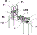
FIG. 1 is a schematic perspective front view of an embodiment of the present invention;
FIG. 2 is a schematic perspective rear view structure in an embodiment of the present invention;
FIG. 3 is a schematic bottom view of an embodiment of the present invention;
FIG. 4 is a schematic diagram of a front side top view configuration in an embodiment of the present invention;
FIG. 5 is a schematic perspective view of a pedestal array according to an embodiment of the present invention;
FIG. 6 is a schematic bottom view of a pedestal according to an embodiment of the present invention;
FIG. 7 is a schematic perspective side view of a stage according to an embodiment of the present invention;
FIG. 8 is a schematic perspective view of a movable button according to an embodiment of the present invention;
FIG. 9 is an enlarged partial structural view of part A in the embodiment of the present invention;
in fig. 1 to 9, the correspondence between the part names or lines and the reference numbers is:
1. a work table; 101. a descending trough; 102. a motor unfolding seat; 2. a scissor regulator A; 3. a pedestal row; 301. a pedestal; 302. a connecting rod; 303. a connecting member; 4. a transmission cylinder A; 401. a hexagonal shaft; 5. a transmission cylinder B; 6. a motor base; 7. a motor; 8. a sub-frame mount; 9. a linkage shaft; 10. a rear frame; 1001. a lead screw A; 11. a fixed seat; 12. an electric cylinder; 13. a top plate; 1301. a pull rod; 1302. a lifting link; 14. a pedestal; 1401. a T-shaped slot; 1402. a screw frame; 1403. a lead screw B; 1404. a sliding pedestal; 1405. side pressing plates; 15. a movable press seat; 1501. a guide strip; 1502. layering; 1503. a scissor regulator B.
Detailed Description
The technical solutions in the embodiments of the present invention will be clearly and completely described below with reference to the drawings in the embodiments of the present invention, and it is obvious that the described embodiments are only a part of the embodiments of the present invention, and not all of the embodiments.
Referring to fig. 1 to 9, an embodiment of the present invention includes: a rapid automatic straight strip profiling device based on machining comprises a workbench 1; a vertical plate is integrally arranged at the front end of the workbench 1, and a scissor regulator A2 is fixedly arranged at the rear side of the vertical plate; two groups of shaft bracket rows 3 are arranged on the front side of the top of the workbench 1 in a transverse sliding manner through guide rails; the shaft bracket row 3 further comprises a shaft bracket 301, a connecting rod 302 and a connecting piece 303; five groups of shaft brackets 301 are integrally arranged at the top of the shaft bracket row 3, and a transmission cylinder A4 and a transmission cylinder B5 are respectively and rotatably arranged in the shaft brackets 301 of the two groups of shaft bracket rows 3; the inner side of the shaft bracket row 3 is rotatably provided with a connecting rod 302 through hinge connection, and the middle of the connecting rods 302 at the two sides is rotatably provided with a connecting piece 303 through hinge connection; the front end of the connecting piece 303 is fixedly connected with the rear end of the scissors adjuster A2; wherein, the transmission cylinder A4 also comprises a hexagonal shaft 401; one side of the transmission cylinder A4 is integrally provided with a hexagonal shaft 401; hexagonal holes are formed in the transmission cylinder B5, and the hexagonal shafts 401 penetrate through the hexagonal holes to be connected in a sliding mode; the hexagonal shaft 401 can drive the transmission cylinder B5 to synchronously rotate in the rotation process of the transmission cylinder A4; the inner side ends of the transmission cylinder A4 and the transmission cylinder B5 are of equal-diameter roller structures and are attached to each other, and circular flange structures are arranged outside the roller structures of the lower transmission cylinder A4 and the transmission cylinder B5; the outside of the transmission cylinder A4 is provided with gear engagement; four groups of descending grooves 101 are formed in the rear side of the workbench 1, and the four groups of descending grooves 101 are uniformly distributed in two rows; a motor unfolding seat 102 is fixedly arranged on one side of the workbench 1; two groups of rear frames 10 are fixedly arranged on two sides of the top of the rear side of the workbench 1; a fixed seat 11 is fixedly arranged in the middle of the top of the rear frame 10; an electric cylinder 12 is fixedly arranged in the middle of the top of the fixed seat 11; a top plate 13 is fixedly arranged at the top of the electric cylinder 12; a pedestal 14 is fixedly arranged in the middle of the top of the rear side of the workbench 1; the pedestal 14 is aligned with the inside of the down tank 101, and the rear frame 10 is aligned with the outside of the down tank 101; the pedestal 14 further comprises a T-shaped slot 1401, a sliding shaft bracket 1404; the two sides of the pedestal 14 are both provided with T-shaped grooves 1401, the inner sides of the tops of the T-shaped grooves 1401 are provided with semicircular grooves, and the inner sides of the tops of the T-shaped grooves 1401 are provided with sliding shaft brackets 1404 in a sliding manner through the semicircular grooves; wherein, a motor seat 6 and an auxiliary frame seat 8 are fixedly arranged on one group of sides of the shaft bracket row 3 provided with the transmission cylinder A4; the tops of the motor seat 6 and the auxiliary frame seat 8 are rotatably provided with a linkage shaft 9 through a shaft frame structure; the outer end of the transmission cylinder A4 is in transmission connection with a bevel gear arranged on the universal driving shaft 9; a motor 7 is fixedly arranged at the top of the motor base 6, and the motor 7 is in transmission connection with a bevel gear arranged at the front end of the linkage shaft 9; the motor base 6 is arranged at the top of the motor unfolding base 102 in a sliding manner through a guide rail, and the sliding direction of the motor base 6 is consistent with that of the shaft bracket row 3; wherein, the top plate 13 further comprises a pull rod 1301 and a lifting connecting rod 1302; four groups of pull rods 1301 are fixedly arranged at the bottom of the periphery of the top plate 13, and the bottoms of the pull rods 1301 penetrate through the descending grooves 101 and are rotatably provided with lifting connecting rods 1302 through hinged connection; wherein, pedestal 14 further comprises a lead screw rack 1402, a lead screw B1403 and a side pressure plate 1405; the outside of the sliding pedestal 1404 is hinged to the top of the lift link 1302 by a hinge connection; a lead screw frame 1402 is fixedly arranged at the bottom of the side of the T-shaped groove 1401, and a lead screw B1403 is rotatably arranged between the lead screw frame 1402 and the inner end of the T-shaped groove 1401; a bump structure is arranged in the middle of the bottom of the sliding shaft frame 1404 in a uniform manner and is in threaded connection with a lead screw B1403; the outer end of the sliding shaft bracket 1404 is rotatably provided with a side pressure plate 1405 through hinge connection; the top surface of side pressure plate 1405 is lower than the top surface of pedestal 14 in the horizontal direction.
Wherein, the rear frame 10 also comprises a screw rod A1001; two groups of lead screws A1001 are rotatably arranged between the tops of the rear frames 10; the bottom of the fixed seat 11 is provided with two groups of movable press seats 15 in a sliding manner through a guide rail, one side of the top of each group of movable press seats 15 is provided with an eccentric lug structure in a uniform manner, and the eccentric lug structures of the two groups of movable press seats 15 are respectively in threaded connection with a group of lead screws A1001; one end of the lead screw A1001 is fixedly provided with a hand wheel.
Wherein, the movable press seat 15 also comprises a guide strip 1501, a pressing strip 1502 and a scissors adjuster B1503; the bottom of the movable pressing seat 15 is integrally provided with a guide strip 1501, and the outside of the guide strip 1501 is provided with a pressing strip 1502 in a sliding manner; a convex plate structure is integrally arranged on the outer sides of the movable press seat 15 and the pressing strip 1502, and a shear fork regulator B1503 is fixedly arranged between the convex plate structures; the bottom edges of the beads 1502 are chamfered.
The working principle is as follows: when the rotary scissors adjuster A2 is used, the connecting piece 303 is moved backwards through the scissors mechanism, the shaft bracket row 3 is pushed aside by the connecting rod 302, the transmission cylinder A4 and the transmission cylinder B5 are unfolded towards two sides, the distance between the transmission cylinder A4 and the transmission cylinder B5 is increased, and the straight bars are clamped by the roller structures of the transmission cylinder A4 and the transmission cylinder B5; starting the motor 7, wherein the motor 7 drives the transmission cylinders A4 to rotate, each group of transmission cylinders A4 is connected and matched with the linkage shaft 9 to synchronously rotate, the transmission cylinders A4 drive the hexagonal shaft 401 to rotate, and the hexagonal shaft 401 drives the transmission cylinder B5 to rotate, so that the straight strips are conveyed; the outside round flange structure that sets up of the gyro wheel structure of downside transmission section of thick bamboo A4 and transmission section of thick bamboo B5 can prevent that the vertical retort from droing, provides the function of supplementary transport for the vertical retort.
According to the requirement of the bending width of the straight strip, the width of the movable pressing seat 15 can be adjusted by rotating the lead screw A1001, the trim fork adjuster B1503 is adjusted to move the pressing strip 1502 downwards and then attach the pressing strip to the surface of the straight strip, and then the lead screw B1403 is rotated to adjust the sliding shaft frame 1404 for the same distance; when the electric cylinder 12 is activated to raise the top plate 13, the top plate 13 lifts the rod 1301, and the side plates 1405 are lifted upward by the movement of the rod 1301 and the lifting link 1302, thereby bending the sides of the straight bars.
It will be evident to those skilled in the art that the invention is not limited to the details of the foregoing illustrative embodiments, and that the present invention may be embodied in other specific forms without departing from the spirit or essential attributes thereof. The present embodiments are therefore to be considered in all respects as illustrative and not restrictive, the scope of the invention being indicated by the appended claims rather than by the foregoing description, and all changes which come within the meaning and range of equivalency of the claims are therefore intended to be embraced therein. Any reference sign in a claim should not be construed as limiting the claim concerned.
Claims (8)
1. The utility model provides a based on machining is with quick automatic straight bar die mould equipment which characterized in that: comprises a workbench (1); a vertical plate is integrally arranged at the front end of the workbench (1), and a shear fork regulator A (2) is fixedly arranged at the rear side of the vertical plate; two groups of shaft bracket rows (3) are arranged on the front side of the top of the workbench (1) in a transverse sliding manner through guide rails; four groups of downlink grooves (101) are formed in the rear side of the workbench (1), and the four groups of downlink grooves (101) are uniformly distributed in two rows; a motor unfolding seat (102) is fixedly arranged on one side of the workbench (1); two groups of rear frames (10) are fixedly arranged on two sides of the top of the rear side of the workbench (1); a fixed seat (11) is fixedly arranged in the middle of the top of the rear frame (10); an electric cylinder (12) is fixedly arranged in the middle of the top of the fixed seat (11); a top plate (13) is fixedly arranged at the top of the electric cylinder (12); a pedestal (14) is fixedly arranged in the middle of the top of the rear side of the workbench (1); the pedestal (14) is aligned with the inner side of the descending groove (101), and the rear frame (10) is aligned with the outer side of the descending groove (101); the pedestal (14) also comprises a T-shaped groove (1401) and a sliding shaft frame (1404); both sides of the pedestal (14) are provided with T-shaped grooves (1401), the inner sides of the tops of the T-shaped grooves (1401) are provided with semicircular grooves, and the inner sides of the tops of the T-shaped grooves (1401) are provided with sliding shaft brackets (1404) in a sliding mode through the semicircular grooves.
2. The rapid automatic straight bar profiling device based on machining according to claim 1, characterized in that: the shaft bracket row (3) also comprises a shaft bracket (301), a connecting rod (302) and a connecting piece (303); five groups of shaft brackets (301) are integrally arranged at the top of the shaft bracket row (3), and two groups of transmission cylinders A (4) and transmission cylinders B (5) are respectively and rotatably arranged in the shaft brackets (301) of the two groups of shaft bracket rows (3); the inner side of the shaft bracket row (3) is rotatably provided with a connecting rod (302) through hinge connection, and the middle of the connecting rods (302) at the two sides is rotatably provided with a connecting piece (303) through hinge connection; the front end of the connecting piece (303) is fixedly connected with the rear end of the scissors adjuster A (2).
3. The rapid automatic straight bar profiling device based on machining according to claim 2, characterized in that: the transmission cylinder A (4) also comprises a hexagonal shaft (401); one side of the transmission cylinder A (4) is integrally provided with a hexagonal shaft (401); hexagonal holes are formed in the transmission cylinder B (5), and hexagonal shafts (401) penetrate through the hexagonal holes to be connected in a sliding mode; the hexagonal shaft (401) can drive the transmission cylinder B (5) to synchronously rotate in the rotation process of the transmission cylinder A (4); the inner side ends of the transmission cylinder A (4) and the transmission cylinder B (5) are of equal-diameter roller structures and are attached to each other, and circular flange structures are arranged outside the roller structures of the transmission cylinder A (4) and the transmission cylinder B (5) on the lower side; the outside of the transmission cylinder A (4) is provided with gear engagement.
4. The rapid automatic straight bar profiling device based on machining according to claim 1, characterized in that: a motor base (6) and an auxiliary frame base (8) are fixedly arranged on one group of sides of the shaft frame row (3) provided with the transmission cylinder A (4); the tops of the motor base (6) and the auxiliary frame base (8) are rotatably provided with a linkage shaft (9) through a shaft frame structure; the outer end of the transmission cylinder A (4) is in transmission connection with a bevel gear arranged on a linkage shaft (9); a motor (7) is fixedly arranged at the top of the motor base (6), and the motor (7) is in transmission connection with the transmission cylinder A (4) in a group; the motor base (6) is arranged at the top of the motor unfolding base (102) in a sliding mode through the guide rail, and the sliding direction of the motor base (6) is consistent with that of the shaft bracket row (3).
5. The rapid automatic straight bar profiling device based on machining according to claim 1, characterized in that: the top plate (13) also comprises a pull rod (1301) and a lifting connecting rod (1302); four groups of pull rods (1301) are fixedly arranged at the bottom of the periphery of the top plate (13), and the bottoms of the pull rods (1301) penetrate through the descending grooves (101) and are rotatably provided with lifting connecting rods (1302) through hinged connection.
6. The rapid automatic straight bar profiling device based on machining according to claim 1, characterized in that: the pedestal (14) further comprises a lead screw frame (1402), a lead screw B (1403) and a side pressure plate (1405); the outer side of the sliding shaft bracket (1404) is hinged with the top of the lifting connecting rod (1302) through a hinge connection; a lead screw frame (1402) is fixedly arranged at the bottom of the side of the T-shaped groove (1401), and a lead screw B (1403) is rotatably arranged between the lead screw frame (1402) and the inner end of the T-shaped groove (1401); a bump structure is arranged in the middle of the bottom of the sliding shaft frame (1404) in a uniform mode and is in threaded connection with the lead screw B (1403); the outer end of the sliding shaft bracket (1404) is rotatably provided with a side pressure plate (1405) through hinge connection; the top surface of the side pressure plate 1405 is lower than the top surface of the pedestal 14 when horizontal.
7. The rapid automatic straight bar profiling device based on machining according to claim 1, characterized in that: the rear frame (10) further comprises a lead screw A (1001); two groups of lead screws A (1001) are rotatably arranged between the tops of the rear frames (10); the bottom of the fixed seat (11) is provided with two groups of movable pressing seats (15) in a sliding way through a guide rail, one side of the top of each group of movable pressing seats (15) is uniformly provided with an eccentric lug structure, and the eccentric lug structures of the two groups of movable pressing seats (15) are respectively in threaded connection with a group of lead screws A (1001); one end of the lead screw A (1001) is fixedly provided with a hand wheel.
8. The rapid automatic straight bar profiling device based on machining according to claim 7, characterized in that: the movable pressing seat (15) also comprises a guide strip (1501), a pressing strip (1502) and a scissor regulator B (1503); the bottom of the movable pressing seat (15) is integrally provided with a guide strip (1501), and a pressing strip (1502) is arranged outside the guide strip (1501) in a sliding manner; the outer sides of the movable pressing seat (15) and the pressing bar (1502) are integrally provided with convex plate structures, and a shear fork regulator B (1503) is fixedly arranged between the convex plate structures; the bottom edge sides of the pressing strips (1502) are all subjected to chamfering treatment.
Priority Applications (1)
| Application Number | Priority Date | Filing Date | Title |
|---|---|---|---|
| CN202011184211.7A CN112547954A (en) | 2020-10-30 | 2020-10-30 | Based on machining is with quick automatic straight bar die mould equipment |
Applications Claiming Priority (1)
| Application Number | Priority Date | Filing Date | Title |
|---|---|---|---|
| CN202011184211.7A CN112547954A (en) | 2020-10-30 | 2020-10-30 | Based on machining is with quick automatic straight bar die mould equipment |
Publications (1)
| Publication Number | Publication Date |
|---|---|
| CN112547954A true CN112547954A (en) | 2021-03-26 |
Family
ID=75042663
Family Applications (1)
| Application Number | Title | Priority Date | Filing Date |
|---|---|---|---|
| CN202011184211.7A Withdrawn CN112547954A (en) | 2020-10-30 | 2020-10-30 | Based on machining is with quick automatic straight bar die mould equipment |
Country Status (1)
| Country | Link |
|---|---|
| CN (1) | CN112547954A (en) |
Cited By (1)
| Publication number | Priority date | Publication date | Assignee | Title |
|---|---|---|---|---|
| CN113477836A (en) * | 2021-09-08 | 2021-10-08 | 山东元捷电子科技有限公司 | Post-processing equipment for semiconductor electronic device production |
-
2020
- 2020-10-30 CN CN202011184211.7A patent/CN112547954A/en not_active Withdrawn
Cited By (1)
| Publication number | Priority date | Publication date | Assignee | Title |
|---|---|---|---|---|
| CN113477836A (en) * | 2021-09-08 | 2021-10-08 | 山东元捷电子科技有限公司 | Post-processing equipment for semiconductor electronic device production |
Similar Documents
| Publication | Publication Date | Title |
|---|---|---|
| CN111389983B (en) | Bracket flanging machine for intelligent pantograph carbon slide plate and use method thereof | |
| CN215698420U (en) | Continuous plate shearing machine for plate processing | |
| CN112547954A (en) | Based on machining is with quick automatic straight bar die mould equipment | |
| CN211888638U (en) | Feeding punching machine | |
| CN109848263B (en) | U-shaped headrest framework bending machine for automobile seat | |
| CN114210794B (en) | Rolling forming machine | |
| CN214055677U (en) | Environment-friendly plywood hot-pressing device | |
| CN111215543B (en) | Plate bending machine | |
| CN210676583U (en) | Side plate forming processing line | |
| CN210788751U (en) | Sheet metal molding press | |
| CN207255335U (en) | A kind of automatic charging plate shearing machine | |
| CN113319161B (en) | Z-shaped bending machine for refrigerator liner production | |
| CN207900643U (en) | A kind of glass window profile preprocess system | |
| CN112676453A (en) | Automatic forming system for double-support vehicle ladder | |
| CN208071148U (en) | A kind of stiff arms formula vehicle frame overturning machine | |
| CN215150618U (en) | Device is cut to integration thermal insulation wall raw materials | |
| CN216801446U (en) | Hydraulic plate bending machine | |
| CN218503058U (en) | Multifunctional sectional material bending machine | |
| CN214391752U (en) | Sheet lifting device | |
| CN219789572U (en) | Printing device for producing special-shaped glass panel | |
| CN220579649U (en) | Waist support cloth cutting equipment | |
| CN216575770U (en) | Plate shearing machine is used in agricultural machinery preparation | |
| CN215544383U (en) | Hydraulic pipe bender with clamping function | |
| CN210877373U (en) | Feeding device for forging hub | |
| CN220592322U (en) | Annular multi-head continuous translation cutting machine |
Legal Events
| Date | Code | Title | Description |
|---|---|---|---|
| PB01 | Publication | ||
| PB01 | Publication | ||
| SE01 | Entry into force of request for substantive examination | ||
| SE01 | Entry into force of request for substantive examination | ||
| WW01 | Invention patent application withdrawn after publication | ||
| WW01 | Invention patent application withdrawn after publication |
Application publication date: 20210326 |