CN112540407B - Pre-stack depth migration anisotropic field establishment method - Google Patents
Pre-stack depth migration anisotropic field establishment method Download PDFInfo
- Publication number
- CN112540407B CN112540407B CN202011389428.1A CN202011389428A CN112540407B CN 112540407 B CN112540407 B CN 112540407B CN 202011389428 A CN202011389428 A CN 202011389428A CN 112540407 B CN112540407 B CN 112540407B
- Authority
- CN
- China
- Prior art keywords
- depth
- target layer
- seismic
- depth migration
- borehole
- Prior art date
- Legal status (The legal status is an assumption and is not a legal conclusion. Google has not performed a legal analysis and makes no representation as to the accuracy of the status listed.)
- Active
Links
- 230000005012 migration Effects 0.000 title claims abstract description 46
- 238000013508 migration Methods 0.000 title claims abstract description 46
- 238000000034 method Methods 0.000 title claims abstract description 17
- 238000004364 calculation method Methods 0.000 claims abstract description 13
- 238000012417 linear regression Methods 0.000 claims abstract description 13
- 238000006243 chemical reaction Methods 0.000 claims abstract description 4
- 239000003245 coal Substances 0.000 description 2
- 238000005553 drilling Methods 0.000 description 2
- 101001121408 Homo sapiens L-amino-acid oxidase Proteins 0.000 description 1
- 102100026388 L-amino-acid oxidase Human genes 0.000 description 1
- 238000010586 diagram Methods 0.000 description 1
- 230000000694 effects Effects 0.000 description 1
- 238000005516 engineering process Methods 0.000 description 1
Images

Classifications
-
- G—PHYSICS
- G01—MEASURING; TESTING
- G01V—GEOPHYSICS; GRAVITATIONAL MEASUREMENTS; DETECTING MASSES OR OBJECTS; TAGS
- G01V1/00—Seismology; Seismic or acoustic prospecting or detecting
- G01V1/28—Processing seismic data, e.g. for interpretation or for event detection
- G01V1/30—Analysis
- G01V1/301—Analysis for determining seismic cross-sections or geostructures
-
- G—PHYSICS
- G01—MEASURING; TESTING
- G01V—GEOPHYSICS; GRAVITATIONAL MEASUREMENTS; DETECTING MASSES OR OBJECTS; TAGS
- G01V1/00—Seismology; Seismic or acoustic prospecting or detecting
- G01V1/28—Processing seismic data, e.g. for interpretation or for event detection
- G01V1/30—Analysis
- G01V1/307—Analysis for determining seismic attributes, e.g. amplitude, instantaneous phase or frequency, reflection strength or polarity
-
- G—PHYSICS
- G01—MEASURING; TESTING
- G01V—GEOPHYSICS; GRAVITATIONAL MEASUREMENTS; DETECTING MASSES OR OBJECTS; TAGS
- G01V2210/00—Details of seismic processing or analysis
- G01V2210/50—Corrections or adjustments related to wave propagation
- G01V2210/51—Migration
- G01V2210/512—Pre-stack
-
- G—PHYSICS
- G01—MEASURING; TESTING
- G01V—GEOPHYSICS; GRAVITATIONAL MEASUREMENTS; DETECTING MASSES OR OBJECTS; TAGS
- G01V2210/00—Details of seismic processing or analysis
- G01V2210/60—Analysis
- G01V2210/63—Seismic attributes, e.g. amplitude, polarity, instant phase
- G01V2210/632—Amplitude variation versus offset or angle of incidence [AVA, AVO, AVI]
Landscapes
- Engineering & Computer Science (AREA)
- Remote Sensing (AREA)
- Physics & Mathematics (AREA)
- Life Sciences & Earth Sciences (AREA)
- Acoustics & Sound (AREA)
- Environmental & Geological Engineering (AREA)
- Geology (AREA)
- General Life Sciences & Earth Sciences (AREA)
- General Physics & Mathematics (AREA)
- Geophysics (AREA)
- Geophysics And Detection Of Objects (AREA)
Abstract
本发明提供一种叠前深度偏移各向异性场建立方法,包括以下步骤:对三维地震各向同性叠前深度偏移成果进行目的层层位解释,得到工区内每个点目的层深度D;在三维地震各向同性叠前深度偏移成果剖面上读取钻孔处目的层的深度D1;根据D1和钻孔目的层的深度D2计算钻孔处各向异性值δ1;对D1和δ1进行线性回归拟合,求取D1和δ1的关系式Y;利用关系式Y和目的层深度D计算工区内每个点的各向异性值δ;利用各向异性值δ建立各向异性场进行三维地震各向异性叠前深度偏移;在三维地震各向异性叠前深度偏移成果剖面上读取钻孔处目的层的深度D2,线性回归拟合得到的关系式Y可用于目的层深度与各向异性值的转化计算。
The present invention provides a pre-stack depth migration anisotropy field establishment method, comprising the following steps: Interpreting the target layer horizon for the three-dimensional seismic isotropic pre-stack depth migration results, and obtaining the depth D of the target layer at each point in the work area ; Read the depth D 1 of the target layer at the borehole on the profile of the 3D seismic isotropic pre-stack depth migration results; calculate the anisotropy value δ 1 at the borehole according to D 1 and the depth D 2 of the target layer in the borehole; Perform linear regression fitting on D 1 and δ 1 to obtain the relational expression Y between D 1 and δ 1 ; use the relational expression Y and the depth D of the target layer to calculate the anisotropy value δ of each point in the work area; use the anisotropic The value δ is used to establish an anisotropy field for 3D seismic anisotropic pre-stack depth migration; read the depth D 2 of the target layer at the borehole on the section of the 3D seismic anisotropic pre-stack depth migration results, and linear regression fit to get The relational expression Y can be used for the conversion calculation of the depth of the target layer and the anisotropy value.
Description
技术领域Technical Field
本发明专利涉及一种叠前深度偏移各向异性场建立方法,适用于对深度精度要求高但是钻孔数据少的工区建立各向异性场进行三维地震各向异性叠前深度偏移使用。The patent of this invention relates to a method for establishing an anisotropic field of pre-stack depth migration, which is suitable for establishing an anisotropic field for three-dimensional seismic anisotropic pre-stack depth migration in work areas with high depth accuracy requirements but little drilling data.
背景技术Background Art
目前叠前深度偏移各向异性场建立只是依靠钻孔处的各向异性值建立各向异性场,方法就是求取每个钻孔处的各向异性值,然后进行插值生成各向异性场,利用各向异性场进行各向异性叠前深度偏移。At present, the anisotropy field of prestack depth migration is established only by relying on the anisotropy value at the borehole. The method is to obtain the anisotropy value at each borehole, and then interpolate to generate the anisotropy field, and use the anisotropy field to perform anisotropic prestack depth migration.
问题和缺点:以往方法在钻孔少的工区,通过插值得到的钻孔之间和边界的个向异性值,往往与真实的各向异性值存在较大的误差,造成叠前深度偏移深度精度低。Problems and shortcomings: In the previous methods, in the work area with few boreholes, the anisotropy values between boreholes and at the boundaries obtained by interpolation often have large errors compared with the true anisotropy values, resulting in low depth accuracy of prestack depth migration.
发明内容Summary of the invention
为了有效解决背景技术的问题,有必要提供一种可提高叠前深度偏移深度精度的叠前深度偏移各向异性场建立方法。In order to effectively solve the problems of the background technology, it is necessary to provide a method for establishing anisotropic field of prestack depth migration that can improve the depth accuracy of prestack depth migration.
本发明的目的是通过以下技术方案实现的:The objective of the present invention is achieved through the following technical solutions:
一种叠前深度偏移各向异性场建立方法,其包括以下步骤:A method for establishing anisotropic field of prestack depth migration comprises the following steps:
S1、对三维地震各向同性叠前深度偏移成果进行目的层层位解释,得到工区内每个点目的层深度D;S1. Interpret the target layer position of the 3D seismic isotropic prestack depth migration results to obtain the target layer depth D at each point in the work area;
S2、在三维地震各向同性叠前深度偏移成果剖面上读取钻孔处目的层的深度D1;S2. Read the depth D 1 of the target layer at the borehole on the 3D seismic isotropic pre-stack depth migration result section;
S3、根据D1和钻孔目的层的深度D2计算钻孔处各向异性值δ1;S3, calculating the anisotropy value δ 1 at the borehole according to D 1 and the depth D 2 of the target layer of the borehole;
S4、对D1和δ1进行线性回归拟合,求取D1和δ1的关系式Y;S4, performing linear regression fitting on D 1 and δ 1 to obtain the relationship Y between D 1 and δ 1 ;
S5、利用关系式Y和目的层深度D计算工区内每个点的各向异性值δ;S5. Calculate the anisotropy value δ of each point in the work area using the relational expression Y and the depth D of the target layer;
S6、利用各向异性值δ建立各向异性场进行三维地震各向异性叠前深度偏移;S6. Using the anisotropy value δ to establish an anisotropy field for 3D seismic anisotropic prestack depth migration;
S7、在三维地震各向异性叠前深度偏移成果剖面上读取钻孔处目的层的深度D2,并和D1对比,如果两者误差小,则线性回归拟合得到的关系式Y可用于目的层深度与各向异性值的转化计算;如果误差大,对关系式Y进行调整,直到误差满足要求。S7. Read the depth D2 of the target layer at the borehole on the 3D seismic anisotropic prestack depth migration result section and compare it with D1 . If the error between the two is small, the relationship Y obtained by linear regression fitting can be used for the conversion calculation between the depth of the target layer and the anisotropy value; if the error is large, adjust the relationship Y until the error meets the requirement.
所述S3所述的钻孔处各向异性值δ1的计算方法为:The calculation method of the anisotropy value δ 1 at the borehole described in S3 is:

所述S4具体为:Y的计算公式为:Y=aX2+bX+c,Y为各向异性值δ1,X为在三维地震各向同性叠前深度偏移成果剖面上的深度D1,a、b、c为通过线性回归拟合得到的系数项。Specifically, S4 is: the calculation formula of Y is: Y=aX 2 +bX+c, Y is the anisotropy value δ 1 , X is the depth D 1 on the 3D seismic isotropic prestack depth migration result section, and a, b, c are coefficients obtained by linear regression fitting.
所述S5中工区内每个点的各向异性值δ的计算方法为:The calculation method of the anisotropy value δ of each point in the working area in S5 is:
δ=a*D2+b*D+c。δ = a*D 2 + b*D + c.
相对于现有技术,本发明的优点在于:Compared with the prior art, the advantages of the present invention are:
本发明专利主要以一种基于目的层深度建立各向异性场的方法,可以提高各向异性场的准确度,提高叠前深度偏移深度精度,提高勘探目的层的深度预测精度。The invention mainly uses a method to establish an anisotropic field based on the depth of the target layer, which can improve the accuracy of the anisotropic field, improve the depth accuracy of the pre-stack depth migration, and improve the depth prediction accuracy of the exploration target layer.
附图说明BRIEF DESCRIPTION OF THE DRAWINGS
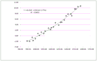
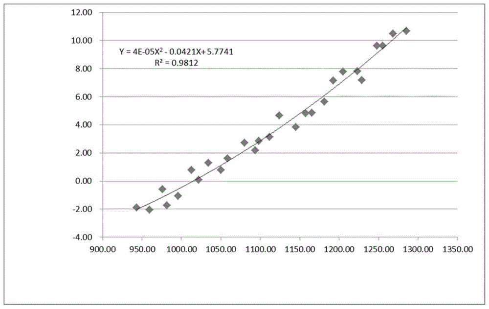
图1为本发明实施例中对利用工区内的27口钻孔处的D1和δ1值,进行线性回归拟合,求取D1和δ1的关系式Y;FIG1 is a linear regression fitting of D1 and δ1 values at 27 boreholes in a work area to obtain a relationship Y between D1 and δ1 in an embodiment of the present invention;
图2为不同的叠前深度偏移的示意图。Figure 2 is a schematic diagram of different prestack depth migrations.
具体实施方式DETAILED DESCRIPTION
为了使本发明的方法流程、特征、成效易于了解,下面结合具体实施方式,进一步阐述本发明。In order to make the method flow, features and effects of the present invention easy to understand, the present invention is further described below in conjunction with specific implementation methods.
本实施例提供一种叠前深度偏移各向异性场建立方法,其包括以下步骤:This embodiment provides a method for establishing anisotropic field of prestack depth migration, which includes the following steps:
1、收集工区三维地震各向同性叠前深度偏移数据,在解释工作站上对三维地震各向同性叠前深度偏移数据剖面上对目的层进行平面间隔20m*20m解释,得到工区内平面间隔20m*20m的目的层深度D;1. Collect 3D seismic isotropic prestack depth migration data in the work area, interpret the target layer on the 3D seismic isotropic prestack depth migration data section at a plane interval of 20m*20m on the interpretation workstation, and obtain the depth D of the target layer at a plane interval of 20m*20m in the work area;
2、收集工区内的钻孔数据,在过钻孔的三维地震各向同性叠前深度偏移成果剖面上读取每个钻孔处目的层的深度D1;2. Collect the borehole data in the work area, and read the depth D 1 of the target layer at each borehole on the 3D seismic isotropic prestack depth migration result section through the borehole;
3、利用各向异性值计算公式,根据D1和钻孔目的层的深度D2计算钻孔处的各向异性值δ1;3. Using the anisotropy value calculation formula, calculate the anisotropy value δ 1 at the borehole according to D 1 and the depth D 2 of the target layer of the borehole;

4、对钻孔处的D1和δ1值,进行线性回归拟合,求取D1和δ1的关系式Y:4. Perform linear regression fitting on the D1 and δ1 values at the drilling site to obtain the relationship Y between D1 and δ1 :
Y=aX2+bX+c,Y为各向异性值δ1,X为在三维地震各向同性叠前深度偏移成果剖面上的深度D1,a、b、c为通过线性回归拟合得到的系数项;通过所述a、b、c,可以算出关系式Y的相关系数R,当相关系数R大于0.8的时候,认为系数项a、b、c满足要求;Y=aX 2 +bX+c, Y is the anisotropy value δ 1 , X is the depth D 1 on the 3D seismic isotropic prestack depth migration result section, a, b, c are coefficients obtained by linear regression fitting; through a, b, c, the correlation coefficient R of the relational expression Y can be calculated, and when the correlation coefficient R is greater than 0.8, it is considered that the coefficients a, b, c meet the requirements;
相关系数R的计算公式为:
其中Cov(X,Y)为X与Y的协方差,Var[X]为X的方差,Var[Y]为Y的方差。Where Cov(X,Y) is the covariance of X and Y, Var[X] is the variance of X, and Var[Y] is the variance of Y.
5、利用关系式Y和目的层深度D计算工区内每个点的各向异性值δ;5. Calculate the anisotropy value δ of each point in the work area using the relationship Y and the target layer depth D;
δ=a*D2+b*D+c;δ=a*D 2 +b*D+c;
6、利用各向异性值δ建立各向异性场进行三维地震各向异性叠前深度偏移:此步骤属于现有技术,利用已有的插值软件将上一步之前计算的目的层的各向异性值δ插值成一个三维的各向异性值δ体,完成利用各向异性值δ建立各向异性场;6. Establishing an anisotropy field using the anisotropy value δ to perform three-dimensional seismic anisotropic prestack depth migration: This step belongs to the prior art. The anisotropy value δ of the target layer calculated before the previous step is interpolated into a three-dimensional anisotropy value δ body using the existing interpolation software to complete the establishment of the anisotropy field using the anisotropy value δ.
7、在三维地震各向异性叠前深度偏移成果剖面上读取钻孔处目的层的深度D2,将D2和D1对比,如果两者误差小,则线性回归拟合得到的关系式Y可用于目的层深度与各向异性值的转化计算;如果D2和D1两者误差大,则需对关系式Y进行调整,具体可以求取三阶Y=aX3+bX2+cX+d或者四阶的关系式Y=aX4+bX3+c X2+dX+e,用重新求取的各向异性值δ建立各向异性场进行三维地震各向异性叠前深度偏移,直到误差满足要求。7. Read the depth D2 of the target layer at the borehole on the profile of the 3D seismic anisotropic prestack depth migration results, and compare D2 with D1 . If the error between the two is small, the relationship Y obtained by linear regression fitting can be used for the conversion calculation of the target layer depth and the anisotropy value; if the error between D2 and D1 is large, the relationship Y needs to be adjusted. Specifically, the third-order Y= aX3 + bX2 +cX+d or the fourth-order relationship Y= aX4 + bX3 + cX2 +dX+e can be obtained. The anisotropy field is established with the re-obtained anisotropy value δ for 3D seismic anisotropic prestack depth migration until the error meets the requirements.
图1是对利用工区内的27口钻孔处的D1和δ1值,进行线性回归拟合,求取D1和δ1的关系式Y,从图中可以看出,D1和δ1有很好的相关性,可以利用深度D1来计算各向异性值δ1。Figure 1 shows the linear regression fitting of D 1 and δ 1 values at 27 boreholes in the work area to obtain the relationship Y between D 1 and δ 1. It can be seen from the figure that D 1 and δ 1 have a good correlation, and the anisotropy value δ 1 can be calculated using the depth D 1 .
表1为井震误差统计表,各向同性叠前深度偏移后,井震误差最大为47.67m;以往方法建立各向异性场进行各向异性叠前深度偏移后,井震误差最大为25.1m,误差较各向同性叠前深度偏移有所减小,但依然较大;完全满足了煤炭等领域对解释成果精度高的要求;新方法建立各向异性场进行各向异性叠前深度偏移后,误差较以往方法建立各向异性场进行各向异性叠前深度偏移有所减小,井震误差最大为2.49m,完全满足了煤炭等领域对解释成果精度高的要求。Table 1 is a statistical table of well-seismic errors. After isotropic prestack depth migration, the maximum well-seismic error is 47.67m. After the previous method was used to establish anisotropic field for anisotropic prestack depth migration, the maximum well-seismic error was 25.1m. The error was smaller than that of isotropic prestack depth migration, but still large. It fully meets the requirements of coal and other fields for high accuracy of interpretation results. After the new method was used to establish anisotropic field for anisotropic prestack depth migration, the error was smaller than that of the previous method. The maximum well-seismic error was 2.49m, which fully meets the requirements of coal and other fields for high accuracy of interpretation results.
附表1井震误差统计表Appendix 1 Statistics of well seismic errors
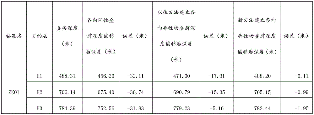


图2显示不同的叠前深度偏移,图2中上部的图是三维地震各向同性的叠前深度偏移连井剖面,剖面深度与钻孔的深度差值大;中间的图是以往根据钻孔插值生成各向异性场的三维地震各向异性的叠前深度偏移连井剖面,剖面深度与钻孔的深度差值较上变的图有所减小,但依然较大;下部的图是利用关系式和目的层深度求取各向异性值,建立各向异性场进行性进行三维地震各向异性的叠前深度偏移连井剖面,得到速度2,剖面深度与钻孔的深度差值很小,深度精度较中间的图有明显提高。Figure 2 shows different pre-stack depth migrations. The upper figure in Figure 2 is a 3D seismic isotropic pre-stack depth migration well section, and the difference between the profile depth and the borehole depth is large; the middle figure is a 3D seismic anisotropic pre-stack depth migration well section that generates anisotropic fields based on borehole interpolation in the past. The difference between the profile depth and the borehole depth is smaller than that of the upper figure, but still large; the lower figure uses the relationship and the depth of the target layer to obtain the anisotropy value, establishes the anisotropic field, and performs 3D seismic anisotropic pre-stack depth migration well section to obtain velocity 2. The difference between the profile depth and the borehole depth is very small, and the depth accuracy is significantly improved compared with the middle figure.
Claims (3)


Priority Applications (1)
| Application Number | Priority Date | Filing Date | Title |
|---|---|---|---|
| CN202011389428.1A CN112540407B (en) | 2020-12-01 | 2020-12-01 | Pre-stack depth migration anisotropic field establishment method |
Applications Claiming Priority (1)
| Application Number | Priority Date | Filing Date | Title |
|---|---|---|---|
| CN202011389428.1A CN112540407B (en) | 2020-12-01 | 2020-12-01 | Pre-stack depth migration anisotropic field establishment method |
Publications (2)
| Publication Number | Publication Date |
|---|---|
| CN112540407A CN112540407A (en) | 2021-03-23 |
| CN112540407B true CN112540407B (en) | 2023-04-25 |
Family
ID=75017034
Family Applications (1)
| Application Number | Title | Priority Date | Filing Date |
|---|---|---|---|
| CN202011389428.1A Active CN112540407B (en) | 2020-12-01 | 2020-12-01 | Pre-stack depth migration anisotropic field establishment method |
Country Status (1)
| Country | Link |
|---|---|
| CN (1) | CN112540407B (en) |
Families Citing this family (1)
| Publication number | Priority date | Publication date | Assignee | Title |
|---|---|---|---|---|
| CN114296137B (en) * | 2021-12-21 | 2024-04-26 | 中国煤炭地质总局地球物理勘探研究院 | Method and system for establishing seismic Q field |
Citations (4)
| Publication number | Priority date | Publication date | Assignee | Title |
|---|---|---|---|---|
| US6785612B1 (en) * | 2003-05-29 | 2004-08-31 | Pgs Americas, Inc. | Seismic velocity update for anisotropic depth migration |
| CN102025531A (en) * | 2010-08-16 | 2011-04-20 | 北京亿阳信通软件研究院有限公司 | Filling method and device thereof for performance data |
| CN103149588A (en) * | 2013-02-20 | 2013-06-12 | 中国石油天然气股份有限公司 | A Method and System for Calculating VTI Anisotropy Parameters Using Well Seismic Calibration |
| CN109581499A (en) * | 2018-11-08 | 2019-04-05 | 成都捷科思石油天然气技术发展有限公司 | A method of structural map is generated using anisotropy pre-stack depth migration |
Family Cites Families (1)
| Publication number | Priority date | Publication date | Assignee | Title |
|---|---|---|---|---|
| US20100135115A1 (en) * | 2008-12-03 | 2010-06-03 | Chevron U.S.A. Inc. | Multiple anisotropic parameter inversion for a tti earth model |
-
2020
- 2020-12-01 CN CN202011389428.1A patent/CN112540407B/en active Active
Patent Citations (4)
| Publication number | Priority date | Publication date | Assignee | Title |
|---|---|---|---|---|
| US6785612B1 (en) * | 2003-05-29 | 2004-08-31 | Pgs Americas, Inc. | Seismic velocity update for anisotropic depth migration |
| CN102025531A (en) * | 2010-08-16 | 2011-04-20 | 北京亿阳信通软件研究院有限公司 | Filling method and device thereof for performance data |
| CN103149588A (en) * | 2013-02-20 | 2013-06-12 | 中国石油天然气股份有限公司 | A Method and System for Calculating VTI Anisotropy Parameters Using Well Seismic Calibration |
| CN109581499A (en) * | 2018-11-08 | 2019-04-05 | 成都捷科思石油天然气技术发展有限公司 | A method of structural map is generated using anisotropy pre-stack depth migration |
Non-Patent Citations (1)
| Title |
|---|
| 任婷 等.基于趋势速度约束的各向异性深度偏移建模与应用.《 CPS/SEG北京2018国际地球物理会议暨展览电子论文集》.2018,479-482. * |
Also Published As
| Publication number | Publication date |
|---|---|
| CN112540407A (en) | 2021-03-23 |
Similar Documents
| Publication | Publication Date | Title |
|---|---|---|
| CN104730579B (en) | A kind of joint static correcting method of ripple in length and breadth based on calculation of near surface shear velocity inverting | |
| CN109541685B (en) | A method for identification of channel sand bodies | |
| CN113031068B (en) | Reflection coefficient accurate base tracking prestack seismic inversion method | |
| CN106646613B (en) | The multiple dimensioned well control modeling of Depth Domain and imaging combination treatment method | |
| WO2010118624A1 (en) | Well constrained horizontal variable h-v curve construting method for seismic wave velocity field construction | |
| CN116184493B (en) | A high-precision velocity field construction method based on well-seismic integration for horizontal well development | |
| CN108254780A (en) | A kind of microseism positioning and anisotropic velocity structure tomographic imaging method | |
| CN109188522B (en) | Velocity field construction method and device | |
| CN111175825B (en) | Depth domain speed modeling method | |
| CN112540407B (en) | Pre-stack depth migration anisotropic field establishment method | |
| CN111239818A (en) | Ancient landform analysis method based on three-dimensional dip angle attribute body correction | |
| CN108957554B (en) | Seismic inversion method in geophysical exploration | |
| CN106324678B (en) | A kind of full waveform inversion method and system based on log data constraint | |
| CN112925022B (en) | Prediction method for anisotropy parameters of shale VTI medium | |
| CN112529981B (en) | A Method for Contour Mapping of Coal Seam Floor in Depth Domain | |
| CN115639594A (en) | A small smooth surface processing method to improve the imaging precision of Jurassic continental strata | |
| CN111190224B (en) | Dynamic sampling full-waveform inversion system and method based on three-dimensional seismic wave reverse illumination | |
| CN107576987A (en) | A Design Method for Horizontal Well Trajectories in Carbonate Beaded Reservoirs | |
| CN116466392B (en) | Stratum velocity model building method of complex structure and stratum velocity model | |
| CN108508479B (en) | Method for inverting three-dimensional gravity-magnetic data of open-ground well in cooperation with target position | |
| CN111596348A (en) | Stratum velocity correction method and device based on acoustic time difference logging data | |
| CN105095634B (en) | A kind of Migration velocity model method for building up based on geological mass | |
| CN115561831A (en) | Method for making earthquake synthetic record | |
| CN116522431A (en) | Stratum pore pressure field establishment method for well seismic data fusion | |
| CN116106970A (en) | Modeling Method of Near-Surface Velocity in Gravel Layer in Piedmont |
Legal Events
| Date | Code | Title | Description |
|---|---|---|---|
| PB01 | Publication | ||
| PB01 | Publication | ||
| SE01 | Entry into force of request for substantive examination | ||
| SE01 | Entry into force of request for substantive examination | ||
| GR01 | Patent grant | ||
| GR01 | Patent grant |