Background
A pressure sensor refers to a device or apparatus that can sense a pressure signal and convert the pressure signal into a usable output electrical signal according to a certain rule. A pressure sensor is usually composed of a pressure sensitive element and a signal processing unit. The traditional pressure sensor is mainly based on a mechanical structure type device, and indicates pressure by deformation of an elastic element, but the structure is large in size and heavy in weight, and cannot provide electrical output. With the rapid development of mobile communication networks, self-powered visual flexible pressure sensors (SP-VFPS) are very urgent in practical applications of intelligent terminals such as intelligent wearable devices, human-computer interaction, artificial electronic skins, and the like. Currently, in flexible pressure sensors, common sensing mechanisms include: resistive, capacitive, piezoelectric, triboelectric, optical. The first four have electrical outputs, while the optical has optical outputs.
Recently, many new optical sensors have emerged, which convert tactile stimuli into macroscopic light, i.e. pressure-visual sensing. Methods of pressure visualization have been reported to include mainly thermochromic, mechanochromic, electrochromic, mechanoluminescent, and electroluminescent. The switching speed of the color changing mechanism is slow, the pressure cannot be quickly responded, the color changing can only be changed among a few colors generally, and the pressure cannot be well quantified. In contrast, a light emitting mechanism with fast response and bright light intensity is more preferable. In the luminescence mechanism, mechanoluminescence can be self-powered, but it requires a large pressure drive and is not suitable for daily use. Overall, these optical sensors do not enable: high sensitivity response to static and dynamic pressure and high resolution mapping over a wide range of pressure detection.
Disclosure of Invention
The invention aims to provide a self-powered visual flexible pressure sensor based on tribo-electroluminescence, and aims to solve the problems of small pressure detection range and low sensitivity of the existing optical sensor.
The invention is realized by the following steps: a self-powered visual flexible pressure sensor based on tribo-electroluminescence comprises a porous layer at the bottom, a light emitting layer in the middle and a charged layer at the top; the porous layer is formed by uniformly distributing red fluorescent powder in a polydimethylsiloxane substrate, and the porous layer contains pores with the average pore diameter of 200-400 mu m; the luminous layer is formed by uniformly distributing green fluorescent powder in a polydimethylsiloxane substrate, and the charged layer is made of fluorinated ethylene propylene.
Preferably, the thickness of the light emitting layer is 500 μm, the thickness of the charged layer is 50 μm, the thickness of the porous layer is 400 μm, the porosity of the porous layer is 21%, and the weight percentage concentration of the red phosphor in the porous layer is 35%.
Preferably, the red phosphor is (Sr, Ca) SiAlN3:Eu2+The fluorescent powder and the green fluorescent powder are ZnS: and (3) Cu fluorescent powder. The average particle size of the red phosphor was 20 μm, and the average particle size of the green phosphor was 50 μm.
The preparation process of the porous layer comprises the following specific steps: the red phosphor and sodium chloride particles were uniformly dispersed in polydimethylsiloxane, which was then scraped onto an acrylic substrate, followed by curing in a constant temperature drying oven at 80 ℃ for 1 hour to form a porous layer.
The preparation process of the luminescent layer comprises the following specific steps: the green phosphor is uniformly mixed in polydimethylsiloxane, then a light emitting layer is formed on the porous layer through a spin coating process, then the light emitting layer is placed in a constant temperature drying oven at 80 ℃ for drying for 1 hour, finally the light emitting layer is stripped and placed in deionized water for a plurality of days to completely dissolve sodium chloride, and then the light emitting layer is dried in the constant temperature drying oven.
The present invention proposes for the first time a triboelectric charging induced electroluminescence (TIEL) SP-VFPS capable of color tuning in response to mechanical stimuli, consisting of two parts: one part is a red porous Photoluminescence (PL) structure and the other part is a TIEL element consisting of a light-emitting layer and a charged layer. Compression of the red porous PL structure under pressure will increase the intensity ratio of green TIEL to red PL and successfully achieve a wide range of color changes. The SP-VFPS showed a rather low detection limit at a friction pressure of 10kPa with an unprecedented high sensitivity (S) at a wide range of pressures>190kPa-1) With a response time of less than 10 milliseconds. In particular, as a demonstration of potential applications, location positioning and shippingDynamic tracking not only can detect static/dynamic forces in dual modes, but can also display pressure profiles in response to color changes. The novel high-performance color-changing SP-VFPS is expected to be widely applied to the fields of interactive wearable equipment, artificial limbs, intelligent robots and the like.
Detailed Description
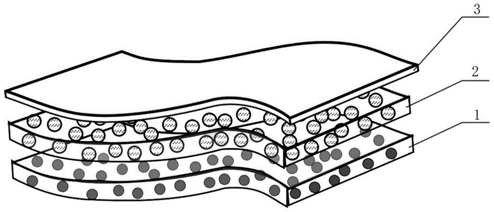
As shown in fig. 1, the self-powered visual flexible pressure sensor based on tribo-electroluminescence provided by the present invention is made of three layers of composite materials, which are: a porous layer 1 at the bottom, a light-emitting layer 2 in the middle, and a charged layer 3 at the top. In the present invention, the porous layer 1 is formed by uniformly distributing red PL phosphor (Sr, Ca) SiAlN in Polydimethylsiloxane (PDMS) matrix3:Eu2+Therefore, in the porous layer 1, that is, the red porous PL layer, the red luminescence mechanism is photoluminescence, and thus red luminescence can be represented by R-PL. The porous layer 1 contains densely distributed pores having an average pore diameter of 200 to 400 [ mu ] m. The light-emitting layer 2 is formed by uniformly distributing green TIEL fluorescent powder ZnS in a PDMS matrix: cu, the light-emitting layer 2 and the electrically conductive layer 3 together constitute a TIEL element, and green light emitted from the light-emitting layer 2 is triboelectric electroluminescence, and thus green light emission is represented by G-TIEL. Preferably, the porous layer 1 has a thickness of 400 μm and the light-emitting layer 2 has a thickness of500 μm and the thickness of the charged layer 3 is 50 μm. Red PL phosphor (Sr, Ca) SiAlN3:Eu2+20 μm, green TIEL phosphor ZnS: the average grain size of Cu was 50 μm.
It was found through experiments that as the charged layer material increases positively in the "triboelectric series", the triboelectric charge density decreases, resulting in a decrease in G-TIEL strength. Therefore, the present invention employs Fluorinated Ethylene Propylene (FEP) as the triboelectric negative electrode material for the charged layer 3.
The middle light emitting layer 2 is a green TIEL light source and the bottom porous layer 1 acts as a colour conversion layer. The light emission signal is collected below the porous layer 1, the collected signal being a combination of the emitted R-PL and G-TIEL leakage. Specifically, a pen-shaped contact object (1 mm in diameter) is driven by a linear stepping motor to rub the charged layer 3; meanwhile, a fiber probe and a force sensor are placed under the bottom porous layer 1, and light on the side of the bottom red porous PL layer is collected and guided to a spectrometer respectively, and the vertical pressure at the contact interface is monitored.
FIG. 2 shows the absorption band of R-PL and its relationship to the emission band of G-TIEL, and energy transfer occurs when the emission band of the donor overlaps with the absorption band of the acceptor, indicating that G-TIEL in the intermediate light-emitting layer can efficiently transmit to the bottom porous layer and be converted to R-PL. With increasing pressure, the transmittance of the porous layer will increase significantly, which will increase the intensity ratio of G-TIEL to R-PL, resulting in a color transition of the SP-VFPS.
In the present example, TIEL-based SP-VFPS was compared with Mechanoluminescence (ML) -based SP-VFPS. The former is a device having the structure shown in fig. 1 of the present invention, and the latter does not have the charged layer 3 shown in fig. 1, as compared with the former. The working principles of the two are different: the TIEL relies on the drastic changes in the triboelectric potential caused by the relative kinetic interaction between two different materials, which can excite the Electroluminescence (EL) of the phosphor along the motion trajectory; but for ML it is due to the strain-inducing piezoelectric potential generated in the piezoelectric material by the strong electron-lattice coupling.
The present inventors first investigated the luminescence intensity of SP-VFPS without red PL phosphor in the porous layer based on TIEL and ML to exclude the conversion between R-PL and G-TIEL. The results show that: in a wide pressure range of 0-2.4MPa, TIEL-based SP-VFPS exhibits significantly higher emission intensity of ZnS: Cu in the light-emitting layer than ML-based SP-VFPS. Correspondingly, in the low pressure range of 0-0.4MPa, the pressure threshold of the ML-based SP-VFPS is 0.2MPa, while the TIEL-based SP-VFPS can be as low as 0.01 MPa. Indicating that the TIEL-based SP-VFPS has a high sensitivity in the low voltage region.
The invention researches the thickness, porosity and weight percentage concentration of the red PL fluorescent powder from the perspective of the porous layer. By studying the relationship between the weight percent concentration of the red PL phosphor in the porous layer and the color conversion efficiency, it was determined that the weight percent concentration of the red PL phosphor in the porous layer was 35% to achieve high color conversion efficiency and ensure elasticity based on PDMS.
The present invention corresponds to the change of coordinates in the color space diagram during the pressure change from 0 to 2.4MPa of the test SP-VFPS by varying the thickness of the porous layer to 300 μm, 400 μm, 500 μm and 600 μm, respectively, as shown in FIG. 3. In the figure, the red coordinates of the pure red PL phosphor are (0.71, 0.32), and the green coordinates of the pure green TIEL phosphor are (0.21, 0.51). Moreover, the SP-VFPS undergoes a sharp color transition between pure R-PL and pure G-TIEL as the pressure increases. As the porous layer becomes thicker, a stronger R-PL may be obtained due to more excited material. The initial color is very close to pure R-PL. However, an excessively thick porous layer will result in less G-t iel leakage and the resulting color will deviate from the pure G-t iel, resulting in a smaller color transition range. When the porous layer has a thickness of 400 μm, the corresponding SP-VFPS has a maximized color transition range.
In addition to this, the present invention changed the porosity (the porosity can be controlled by changing the content of NaCl powder) to 0%, 11%, 21% and 32%, respectively, corresponding to the change of coordinates in the color space diagram during the pressure change from 0 to 2.4MPa of the test SP-VFPS, as shown in fig. 4. In the figure, as the porosity increases, the final color will approach pure G-TIEL even with more leakage. However, the shortage of red PL phosphor causes the initial color to deviate from pure R-PL, resulting in a smaller color transition range. Thus, the SP-VFPS with a porosity of 21% exhibits the largest color transition range.
The corresponding emission spectra of SP-VFPS (porous layer thickness 400 μm, porosity 21%) at different applied pressures are shown in FIG. 5. Spectral changes were observed between pure R-PL peaks at 650nm and pure G-TIEL peaks at 510nm, respectively, further demonstrating the excellent color conversion capability of SP-VFPS.
In addition, a cycling experiment was performed by sliding on the surface of the charged layer in a reciprocating manner under a pressure of 1.6 MPa. The luminescence intensity of the red and green peaks remained essentially unchanged after 20000 cycles, indicating that the color change ability of SP-VFPS has excellent stability and reproducibility.
However, color conversion for SP-VFPS is typically limited to dynamic force sensing applications. By utilizing the coupling effect between contact electrification and electrostatic induction, the SP-VFPS in the invention can be combined with flexible transparent silver nanowires (Ag NWs/PDMS) to be used as a single-electrode triboelectric nano-generator (TENG), as shown in FIG. 6, a silver nanowire thin film array 4 is arranged between a light emitting layer 2 and a porous layer 1, when a pen approaches or leaves a charged layer 3, the local electric field distribution can be changed, so that electronic exchange can occur between the silver nanowire thin film array 4 and the ground to balance the potential change on the silver nanowire thin film array 4, and thus induction current can be generated. Thus, the SP-VFPS enables dual mode detection of static and dynamic forces through color tunable TIEL and triboelectricity.
The preparation process of the SP-VFPS comprises the following steps: laser cutting is used for preparing the product with the size of 4 × 4 × 0.3cm3And a square PET frame with side edges of 4cm and a thickness of 100 μm, and adhering the PET frame to the acrylic base material. 1.4g of red PL phosphor and 1.2g of NaCl particles were uniformly dispersed in 2.6g of PDMS, which was then scraped onto an acrylic substrate to which a PET frame was attached, followed by curing at 80 ℃ for 1h in a constant temperature drying oven. 2g of ZnS: cu was uniformly mixed in 4g of PDMS and spin-coated at 500rpm for 20 seconds to deposit a green light-emitting layer on the cured red porous PL layer, which was then placed at 80 deg.CThe flask was left for 1 hour and finally peeled off and placed in deionized water for 7 days to completely dissolve NaCl and dried in the flask for later use.
The present invention proposes for the first time a SP-VFPS relying on compressed pores, capable of making a color tunable TIEL in response to mechanical stimuli. The novel SP-VFPS exhibits a relatively low friction pressure detection limit
And has unprecedented high sensitivity (S) over a wide range of pressures>190kPa
-1) With a response time of less than 10 milliseconds. In addition, it can also visually display the stress distribution during the duration of the applied pressure. To demonstrate potential applications, based on the coupling effect of contact charging and electrostatic induction, the present SP-VFPS can be easily combined with flexible transparent Ag NWs/PDMS electrodes, used as a single electrode triboelectric nano-generator (TENG) matrix (4 × 4 array), enabling position localization and motion tracking in electro-optic dual mode to detect static/dynamic pressure. This is the first demonstration of implementing color tunable TIELs in an all-in-one device and demonstrates real-world potential applications in future self-powered visual sensing systems.