CN112408169B - Damping device for high-speed elevator and damping system thereof - Google Patents
Damping device for high-speed elevator and damping system thereof Download PDFInfo
- Publication number
- CN112408169B CN112408169B CN201910773106.8A CN201910773106A CN112408169B CN 112408169 B CN112408169 B CN 112408169B CN 201910773106 A CN201910773106 A CN 201910773106A CN 112408169 B CN112408169 B CN 112408169B
- Authority
- CN
- China
- Prior art keywords
- damping
- shock absorption
- fixedly connected
- metal
- plate
- Prior art date
- Legal status (The legal status is an assumption and is not a legal conclusion. Google has not performed a legal analysis and makes no representation as to the accuracy of the status listed.)
- Active
Links
Images


Classifications
-
- B—PERFORMING OPERATIONS; TRANSPORTING
- B66—HOISTING; LIFTING; HAULING
- B66B—ELEVATORS; ESCALATORS OR MOVING WALKWAYS
- B66B11/00—Main component parts of lifts in, or associated with, buildings or other structures
- B66B11/04—Driving gear ; Details thereof, e.g. seals
- B66B11/08—Driving gear ; Details thereof, e.g. seals with hoisting rope or cable operated by frictional engagement with a winding drum or sheave
-
- F—MECHANICAL ENGINEERING; LIGHTING; HEATING; WEAPONS; BLASTING
- F16—ENGINEERING ELEMENTS AND UNITS; GENERAL MEASURES FOR PRODUCING AND MAINTAINING EFFECTIVE FUNCTIONING OF MACHINES OR INSTALLATIONS; THERMAL INSULATION IN GENERAL
- F16F—SPRINGS; SHOCK-ABSORBERS; MEANS FOR DAMPING VIBRATION
- F16F15/00—Suppression of vibrations in systems; Means or arrangements for avoiding or reducing out-of-balance forces, e.g. due to motion
- F16F15/02—Suppression of vibrations of non-rotating, e.g. reciprocating systems; Suppression of vibrations of rotating systems by use of members not moving with the rotating systems
- F16F15/04—Suppression of vibrations of non-rotating, e.g. reciprocating systems; Suppression of vibrations of rotating systems by use of members not moving with the rotating systems using elastic means
- F16F15/06—Suppression of vibrations of non-rotating, e.g. reciprocating systems; Suppression of vibrations of rotating systems by use of members not moving with the rotating systems using elastic means with metal springs
Abstract
The invention discloses a damping device for a high-speed elevator, which comprises a bottom damping mechanism, a middle supporting mechanism and a rotating mechanism, wherein the bottom damping mechanism comprises a concrete damping table, a damping plate, a metal damping frame, a side fastening rod, a metal damping base, a damping fixing plate, a damping damper and a damping pad, the top of the concrete damping table is fixedly connected with the damping plate, the damping device performs primary buffering through the matching use of the damping fixing table and the metal supporting plate, and then buffers the shaking generated by a steel rope through the matching use of the damping pad at the top of the metal damping base and the damping dampers at two sides of the metal damping base, thereby reducing the shaking of a lift car, solving the problem that the existing high-speed elevator generates larger noise due to larger vibration amplitude in the running process and reducing the noise generated by the elevator in the running process, thereby bringing better look and feel and experience to passengers.
Description
Technical Field
The invention relates to the technical field of elevators, in particular to a damping device for a high-speed elevator and a damping system thereof.
Background
The elevator is a permanent transportation device which serves a plurality of specific floors in a building, the car of the elevator runs on at least two rows of rigid track motion devices which are vertical to the horizontal plane or have an inclination angle smaller than 15 degrees with a plumb line, the elevator is also provided with steps, a step plate is arranged on a track to continuously run, the elevator is commonly called an escalator or an automatic sidewalk, the elevator is used as an indispensable vertical transportation tool in modern life, the most intuitive requirement of passengers on comfort needs to be improved, the vibration of the elevator is an important reason causing discomfort, the vibration of the elevator is more obvious in the high-speed elevator, the social requirement on the high-speed elevator is larger and larger along with the development of times, the existing elevator adopts a permanent magnet synchronous traction machine as power, the occupation area of a machine room is greatly reduced, and the elevator has the advantages of low energy consumption, energy conservation, high efficiency, high lifting speed and the like, and the development of the property to the direction of an ultra-high floor is greatly promoted, but the aggravation of vibration and noise is brought when elevator speed promotes, and under normal condition, the time of taking is short and the vibrations amplitude is little, can not influence passenger's safety, nevertheless vibration reaches a definite value, and when the frequency was in people's sensitive area, perhaps elevator braking characteristic is poor, all can make the passenger feel obvious uncomfortable.
Current elevator car when moving from top to bottom along the guide rail, with air friction, car air all around is compressed, and the friction can produce wind and make an uproar, and sound is exactly the embodiment of vibration, and the elevator is at the operation in-process promptly, can produce the vibration, and this kind of vibration can be very big influence passenger's impression and experience, for this reason, provides a damping device and shock mitigation system for high-speed elevator.
Disclosure of Invention
The present invention is directed to a damping device for a high-speed elevator and a damping system thereof to solve the above problems of the related art.
In order to achieve the purpose, the invention provides the following technical scheme: a damping device for a high-speed elevator comprises a bottom damping mechanism, a middle supporting mechanism and a rotating mechanism, wherein the bottom damping mechanism comprises a concrete damping table, a damping plate, a metal damping frame, a side fastening rod, a metal damping base, a damping fixing plate, a damping damper and a damping pad;
the middle supporting mechanism is positioned at the top of the bottom damping mechanism and comprises a metal supporting plate, a damping fixing table and a fixing block, the top of the metal supporting plate is fixedly connected with the damping fixing table, and the top of the damping fixing table is fixedly connected with the fixing block;
the rotating mechanism is positioned at the top of the middle supporting mechanism and comprises a connecting shaft, a gear reducer, a rotating shaft, a traction wheel, a steel rope, an upper cover plate, a lower cover plate, an outer side baffle, a fixing bolt M20, a locking bolt, a bearing fixing seat and a winding drum.
As further preferable in the present technical solution: the one end of even axle runs through one side of outside baffle and rotates and be connected with the bearing fixing base, the outside fixedly connected with gear reducer who links the axle, one side fixedly connected with rotation axis that gear reducer kept away from even axle, the outside of rotation axis is through locking bolt fixedly connected with driving sheave, the surface cover of driving sheave is equipped with the steel cable, the reel is installed in the outside of steel cable.
As further preferable in the present technical solution: an upper cover plate is installed at the top of the gear reducer, a lower cover plate is installed at the bottom of the gear reducer, and an outer side baffle is installed on one side, close to the connecting shaft, of the gear reducer.
As further preferable in the present technical solution: the top of the metal shock absorption base is fixedly connected with a shock absorption pad.
As further preferable in the present technical solution: the bottom of the bearing fixing seat is fixedly connected with the top of the fixing block.
As further preferable in the present technical solution: the number of the damping fixing plates and the number of the shock absorption dampers are all set to six.
As further preferable in the present technical solution: the bottom of the lower cover plate is fixedly connected with the top of the damping fixed station through fixing bolts M20, and the number of the fixing bolts M20 is twelve.
As further preferable in the present technical solution: the length of metal shock attenuation base sets up to 2800 mm-3200 mm, and the height sets up to 700-800 mm, and the width sets up to 1750-1850 mm.
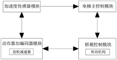
The invention also provides a damping system for the high-speed elevator, which comprises an acceleration sensor module, an elevator main control module, a car control module and an actuator encoder module, wherein the electrical output end of the acceleration sensor module is connected with the electrical input end of the elevator main control module, the elevator main control module and the car control module are mutually connected, the car control module and the actuator encoder module are mutually connected, and the actuator encoder module and the acceleration sensor module are mutually connected.
Compared with the prior art, the invention has the beneficial effects that:
according to the invention, the damping fixing table and the metal supporting plate are used in a matched manner to perform primary buffering, and then the vibration cushion at the top of the metal damping base and the damping dampers at two sides of the metal damping base are used in a matched manner to buffer the vibration generated by the steel rope again, so that the vibration of the car can be reduced, the problem that the existing high-speed elevator is poor in riding experience due to large vibration amplitude and large noise generated due to large vibration amplitude in the running process is solved, the stability of the high-speed elevator in the running process is improved, the noise generated in the running process of the elevator is reduced, and therefore, better impression and experience are brought to passengers.
Drawings
FIG. 1 is a schematic structural view of the present invention;
FIG. 2 is a side view of the present invention;
FIG. 3 is a top view of the present invention;
FIG. 4 is a schematic structural diagram of a metal shock mount according to the present invention;
FIG. 5 is a schematic structural view of the damping mount of the present invention;
FIG. 6 is a schematic structural view of an upper cover plate according to the present invention;
FIG. 7 is a schematic structural view of a lower cover plate according to the present invention;
FIG. 8 is a schematic view of the construction of the outer baffle of the present invention;
FIG. 9 is a block diagram of the system of the present invention.
In the figure: 1. a bottom damping mechanism; 101. a concrete damping table; 102. a damper plate; 103. a metal shock-absorbing mount; 104. a side fastening bar; 105. a metal shock-absorbing base; 106. a damping fixing plate; 107. a shock absorbing damper; 108. a shock pad; 2. a middle support mechanism; 201. a metal support plate; 202. a damping fixed table; 203. a fixed block; 3. a rotating mechanism; 301. a connecting shaft; 302. a gear reducer; 303. a rotating shaft; 304. a traction sheave; 305. a steel cord; 306. an upper cover plate; 307. a lower cover plate; 308. an outer baffle; 309. fixing bolt M20; 310. locking the bolt; 311. a bearing fixing seat; 312. and (4) winding the drum.
Detailed Description
The technical solutions in the embodiments of the present invention will be clearly and completely described below with reference to the drawings in the embodiments of the present invention, and it is obvious that the described embodiments are only a part of the embodiments of the present invention, and not all of the embodiments. All other embodiments, which can be derived by a person skilled in the art from the embodiments given herein without making any creative effort, shall fall within the protection scope of the present invention.
Examples
Referring to fig. 1-8, the present invention provides a technical solution: a damping device for a high-speed elevator comprises a bottom damping mechanism 1, a middle supporting mechanism 2 and a rotating mechanism 3, the bottom shock absorbing mechanism 1 comprises a concrete shock absorbing platform 101, a shock absorbing plate 102, a metal shock absorbing frame 103, a side fastening rod 104, a metal shock absorbing base 105, a damping fixing plate 106, a shock absorbing damper 107 and a shock absorbing pad 108, the top of the concrete damping table 101 is fixedly connected with a damping plate 102, the top of the damping plate 102 is fixedly connected with a metal damping frame 103, one side of the metal shock absorption frame 103 is fixedly connected with a side fastening rod 104, the top of the metal shock absorption frame 103 is fixedly connected with a metal shock absorption base 105, damping fixing plates 106 are fixedly connected to two sides of the metal damping base 105, a damping damper 107 is fixedly connected to the bottoms of the damping fixing plates 106, and a damping pad 108 is fixedly connected to the top of the metal damping base 105;
the middle supporting mechanism 2 is positioned at the top of the bottom damping mechanism 1, the middle supporting mechanism 2 comprises a metal supporting plate 201, a damping fixed table 202 and a fixed block 203, the top of the metal supporting plate 201 is fixedly connected with the damping fixed table 202, and the top of the damping fixed table 202 is fixedly connected with the fixed block 203;
the rotating mechanism 3 is positioned at the top of the middle supporting mechanism 2, and the rotating mechanism 3 comprises a connecting shaft 301, a gear reducer 302, a rotating shaft 303, a traction sheave 304, a steel rope 305, an upper cover plate 306, a lower cover plate 307, an outer baffle plate 308, a fixing bolt 309, a locking bolt 310, a bearing fixing seat 311 and a winding drum 312.
In this embodiment, specifically: one end of the connecting shaft 301 runs through one side of the outer side baffle 308 and is rotatably connected with a bearing fixing seat 311, the outer side fixedly connected with gear reducer 302 of the connecting shaft 301, one side fixedly connected with rotating shaft 303 of the connecting shaft 301 is kept away from by the gear reducer 302, the outer side of the rotating shaft 303 is fixedly connected with a traction sheave 304 through a locking bolt 310, a steel rope 305 is sleeved on the surface of the traction sheave 304, a winding drum 312 is installed on the outer side of the steel rope 305, and through the arrangement, the transmission form is set to be the gear reducer 302, so that the connecting shaft is simple in structure, suitable for occasions with wide loads, stable in transmission, anti-seismic, long in service life, easy to maintain equipment and the like, and the stability and the reliability of the rotating mechanism 3 are guaranteed.
In this embodiment, specifically: an upper cover plate 306 is installed at the top of the gear reducer 302, a lower cover plate 307 is installed at the bottom of the gear reducer 302, an outer side baffle 308 is installed on one side, close to the connecting shaft 301, of the gear reducer 302, and the integrity of the gear reducer 302 is protected through the arrangement.
In this embodiment, specifically: the top fixedly connected with shock pad 108 of metal shock mount 105 through above setting, has reduced the frictional force between metal shock mount 105 and the metal backup pad 201, has improved bottom damper 1's stability simultaneously.
In this embodiment, specifically: the bottom of bearing fixing seat 311 and the top fixed connection of fixed block 203 through above setting, have improved bearing fixing seat 311's stability to improve rotation axis 303's stability, reduced slewing mechanism 3 and rocked in the course of the work.
In this embodiment, specifically: the number of the damping fixing plate 106 and the number of the damping dampers 107 are six, and through the arrangement, the resistance of the metal damping base 105 in motion is improved, the energy of the metal damping base 105 in motion is reduced, the inherent vibration energy of the metal damping base 105 can be well absorbed, the resistance between the metal damping base 105 and the air is reduced to a great extent, and the wind noise is reduced.
In this embodiment, specifically: the bottom of the lower cover plate 307 is fixedly connected with the top of the damping fixing table 202 through fixing bolts 309, the number of the fixing bolts 309 is twelve, and through the arrangement, the stability of the lower cover plate 307 is improved, so that the stability of the gear reducer 302 is improved, and the stability of the whole rotating mechanism 3 is improved.
In this embodiment, specifically: metal shock attenuation base 105's length sets up to 2800 mm-3200 mm, highly set up to 700-800 mm, the width sets up to 1750-1850 mm, through above setting, metal shock attenuation base 105's material is chooseed for use and is 45 steel, possess good reliability, high strength, density is little relatively, better plasticity and toughness have, the structure is the same can reduce the construction degree of difficulty, steel structure leakproofness is good, steel is lively, easily rust, it is controllable nevertheless to plate the type of paint, can not corrode very seriously, and lead to the phenomenon emergence out of control appearing in the use, no corrosive medium under general environment, the rust cleaning of ordinary steel construction, then scribble qualified cladding material again, it is not serious to corrode.
The invention also provides a damping system for a high-speed elevator as shown in fig. 9, which comprises an acceleration sensor module, an elevator main control module, a car control module and an actuator encoder module, wherein the electrical output end of the acceleration sensor module is connected with the electrical input end of the elevator main control module, the elevator main control module is mutually connected with the car control module, the car control module is mutually connected with the actuator encoder module, and the actuator encoder module is mutually connected with the acceleration sensor module.
When the elevator car vibration damping device is used, when an acceleration sensor at the bottom of the elevator car senses the vibration of the car, data is calculated through a control algorithm according to the change relation between the vibration and time, corresponding control force is output to a rotating mechanism 3 in a car control module through an elevator main control module, then a gear reducer 302 in an actuator and encoder module drives a rotating shaft 303 to rotate, the rotating shaft 303 drives a traction wheel 304 to rotate, the traction wheel 304 drives the car to do deceleration or acceleration motion through a steel rope 305, the generated vibration is used by matching a damping fixed platform 202 and a metal supporting plate 201 to perform primary buffering in the process of driving the car to move through the steel rope 305, then the shake generated by the steel rope 305 is buffered again through the matching use between a damping pad 108 at the top of the metal damping base 105 and damping dampers 107 at two sides of the metal damping base 105, thereby can reduce the rocking that causes the car, bring better impression and experience for the passenger.
Although embodiments of the present invention have been shown and described, it will be appreciated by those skilled in the art that changes, modifications, substitutions and alterations can be made in these embodiments without departing from the principles and spirit of the invention, the scope of which is defined in the appended claims and their equivalents.
Claims (1)
1. The utility model provides a damping device for express elevator, includes bottom damper (1), middle part supporting mechanism (2) and slewing mechanism (3), its characterized in that: the bottom shock absorption mechanism (1) comprises a concrete shock absorption table (101), a shock absorption plate (102), a metal shock absorption frame (103), a side fastening rod (104), a metal shock absorption base (105), a damping fixing plate (106), a shock absorption damper (107) and a shock absorption pad (108), the top of the concrete shock absorption table (101) is fixedly connected with the shock absorption plate (102), the top of the shock absorption plate (102) is fixedly connected with the metal shock absorption frame (103), one side of the metal shock absorption frame (103) is fixedly connected with the side fastening rod (104), the top of the metal shock absorption frame (103) is fixedly connected with the metal shock absorption base (105), two sides of the metal shock absorption base (105) are fixedly connected with the damping fixing plate (106), and the bottom of the damping fixing plate (106) is fixedly connected with the shock absorption damper (107);
the middle supporting mechanism (2) is positioned at the top of the bottom damping mechanism (1), the middle supporting mechanism (2) comprises a metal supporting plate (201), a damping fixing table (202) and a fixing block (203), the damping fixing table (202) is fixedly connected to the top of the metal supporting plate (201), and the fixing block (203) is fixedly connected to the top of the damping fixing table (202);
the rotating mechanism (3) is positioned at the top of the middle supporting mechanism (2), and the rotating mechanism (3) comprises a connecting shaft (301), a gear reducer (302), a rotating shaft (303), a traction sheave (304), a steel rope (305), an upper cover plate (306), a lower cover plate (307), an outer side baffle plate (308), a fixing bolt M20(309), a locking bolt (310), a bearing fixing seat (311) and a winding drum (312);
one end of the connecting shaft (301) penetrates through one side of the outer side baffle (308) and is rotatably connected with a bearing fixing seat (311), the outer side of the connecting shaft (301) is fixedly connected with a gear reducer (302), one side, far away from the connecting shaft (301), of the gear reducer (302) is fixedly connected with a rotating shaft (303), the outer side of the rotating shaft (303) is fixedly connected with a traction sheave (304) through a locking bolt (310), a steel rope (305) is sleeved on the surface of the traction sheave (304), and a winding drum (312) is installed on the outer side of the steel rope (305);
an upper cover plate (306) is mounted at the top of the gear reducer (302), a lower cover plate (307) is mounted at the bottom of the gear reducer (302), and an outer side baffle (308) is mounted on one side, close to the connecting shaft (301), of the gear reducer (302);
the top of the metal shock absorption base (105) is fixedly connected with a shock absorption pad (108);
the bottom of the bearing fixing seat (311) is fixedly connected with the top of the fixing block (203);
the number of the damping fixing plates (106) and the number of the shock absorption dampers (107) are six;
the bottom of the lower cover plate (307) is fixedly connected with the top of the shock absorption fixing table (202) through fixing bolts M20(309), and the number of the fixing bolts M20(309) is twelve;
the length of the metal shock absorption base (105) is 2800 mm-3200 mm, the height is 700-800 mm, and the width is 1750-1850 mm;
including acceleration sensor module, elevator main control module, car control module and actor with the encoder module, the electrical output of acceleration sensor module is connected with elevator main control module's electrical input end, elevator main control module and car control module interconnect, car control module and actor with the encoder module interconnect, actor with the encoder module interconnect.
Priority Applications (1)
| Application Number | Priority Date | Filing Date | Title |
|---|---|---|---|
| CN201910773106.8A CN112408169B (en) | 2019-08-21 | 2019-08-21 | Damping device for high-speed elevator and damping system thereof |
Applications Claiming Priority (1)
| Application Number | Priority Date | Filing Date | Title |
|---|---|---|---|
| CN201910773106.8A CN112408169B (en) | 2019-08-21 | 2019-08-21 | Damping device for high-speed elevator and damping system thereof |
Publications (2)
| Publication Number | Publication Date |
|---|---|
| CN112408169A CN112408169A (en) | 2021-02-26 |
| CN112408169B true CN112408169B (en) | 2022-04-19 |
Family
ID=74779928
Family Applications (1)
| Application Number | Title | Priority Date | Filing Date |
|---|---|---|---|
| CN201910773106.8A Active CN112408169B (en) | 2019-08-21 | 2019-08-21 | Damping device for high-speed elevator and damping system thereof |
Country Status (1)
| Country | Link |
|---|---|
| CN (1) | CN112408169B (en) |
Families Citing this family (2)
| Publication number | Priority date | Publication date | Assignee | Title |
|---|---|---|---|---|
| CN114526897B (en) * | 2022-01-25 | 2023-07-11 | 江苏理工学院 | Dynamic and static loading comprehensive test bed for shock absorption damper |
| CN114920110B (en) * | 2022-06-24 | 2023-09-19 | 北京博大新元房地产开发有限公司 | Sound insulation and noise reduction device for elevator and installation method |
Citations (7)
| Publication number | Priority date | Publication date | Assignee | Title |
|---|---|---|---|---|
| JP2004083223A (en) * | 2002-08-27 | 2004-03-18 | Fujitec Co Ltd | Reciprocating body drive mechanism |
| CN102606672A (en) * | 2012-03-26 | 2012-07-25 | 厦门嘉达环保建造工程有限公司 | Vibration isolation balance mechanism of tractor |
| CN203998511U (en) * | 2014-09-02 | 2014-12-10 | 韦伯电梯有限公司 | Elevator traction machine shock absorption device |
| CN204852161U (en) * | 2015-07-31 | 2015-12-09 | 杭州西奥电梯有限公司 | A damping device for hauler |
| CN106365020A (en) * | 2016-12-07 | 2017-02-01 | 常州工邦减振设备有限公司 | Novel elevator tractor belt swing-resistant damping device |
| CN206798901U (en) * | 2017-05-12 | 2017-12-26 | 杭州新马电梯有限公司 | A kind of express elevator damped noise reduction device |
| CN207687258U (en) * | 2017-11-09 | 2018-08-03 | 江西现代职业技术学院 | A kind of damping base of elevator traction machine |
Family Cites Families (2)
| Publication number | Priority date | Publication date | Assignee | Title |
|---|---|---|---|---|
| CN105605150A (en) * | 2016-02-03 | 2016-05-25 | 天津盛同科技有限公司 | Mechanical equipment damping device |
| CN206939456U (en) * | 2017-01-10 | 2018-01-30 | 新昌县南明街道宝丰隆咨询服务部 | A kind of aero-engine damping packing case |
-
2019
- 2019-08-21 CN CN201910773106.8A patent/CN112408169B/en active Active
Patent Citations (7)
| Publication number | Priority date | Publication date | Assignee | Title |
|---|---|---|---|---|
| JP2004083223A (en) * | 2002-08-27 | 2004-03-18 | Fujitec Co Ltd | Reciprocating body drive mechanism |
| CN102606672A (en) * | 2012-03-26 | 2012-07-25 | 厦门嘉达环保建造工程有限公司 | Vibration isolation balance mechanism of tractor |
| CN203998511U (en) * | 2014-09-02 | 2014-12-10 | 韦伯电梯有限公司 | Elevator traction machine shock absorption device |
| CN204852161U (en) * | 2015-07-31 | 2015-12-09 | 杭州西奥电梯有限公司 | A damping device for hauler |
| CN106365020A (en) * | 2016-12-07 | 2017-02-01 | 常州工邦减振设备有限公司 | Novel elevator tractor belt swing-resistant damping device |
| CN206798901U (en) * | 2017-05-12 | 2017-12-26 | 杭州新马电梯有限公司 | A kind of express elevator damped noise reduction device |
| CN207687258U (en) * | 2017-11-09 | 2018-08-03 | 江西现代职业技术学院 | A kind of damping base of elevator traction machine |
Non-Patent Citations (1)
| Title |
|---|
| 电梯系统垂直振动分析与抑制;张长友等;《振动与冲击》;20031230(第04期);第74-77页 * |
Also Published As
| Publication number | Publication date |
|---|---|
| CN112408169A (en) | 2021-02-26 |
Similar Documents
| Publication | Publication Date | Title |
|---|---|---|
| CN112408169B (en) | Damping device for high-speed elevator and damping system thereof | |
| CN208732401U (en) | A kind of integral type is without bracket steel band platform villa elevator | |
| CN203048355U (en) | Elevator crossbar device | |
| WO2007134490A1 (en) | Traction driving elevator system | |
| CN204607309U (en) | A kind of compensating rope of elevator anti-bouncing device | |
| CN205099159U (en) | Elevator lift car damping device | |
| CN202912533U (en) | Single-winding complex shock absorbing device of high-speed elevator traction main engine load-bearing component | |
| CN2923627Y (en) | Guide-wheel speed-limiting device | |
| CN214003743U (en) | Multiple absorbing no computer lab elevator | |
| CN210064946U (en) | Small frame for gantry crane | |
| CN201864409U (en) | Novel suspension device for elevator car | |
| CN210914864U (en) | Foundation-pit-free elevator anti-seismic connecting device | |
| CN202609731U (en) | Shock isolation pedestal of elevator main machine | |
| CN205990140U (en) | A kind of passenger elevator without machine room with damping portal frame | |
| CN206580415U (en) | A kind of elevator emergency brake safety device | |
| CN211419240U (en) | Tractor mounting frame for machine-room-free cargo elevator | |
| CN105173991B (en) | Elevator car shock absorbing device | |
| CN215854507U (en) | Special safe in utilization's of elevator shock attenuation elevator guide rail | |
| CN207361562U (en) | A kind of shock-absorbing type emergency staircase compartment | |
| CN205099168U (en) | Elevator without engine room | |
| CN216377079U (en) | Novel elevator car bottom structure | |
| CN211169415U (en) | Shallow pit economical elevator without counter-weight design | |
| CN212292461U (en) | Super-speed elevator structure | |
| CN210763806U (en) | Right-angle through type traction elevator | |
| CN210457070U (en) | Variable speed elevator with buffer structure |
Legal Events
| Date | Code | Title | Description |
|---|---|---|---|
| PB01 | Publication | ||
| PB01 | Publication | ||
| SE01 | Entry into force of request for substantive examination | ||
| SE01 | Entry into force of request for substantive examination | ||
| GR01 | Patent grant | ||
| GR01 | Patent grant |