CN112376742A - Assembled partition wall fossil fragments frame and partition wall - Google Patents
Assembled partition wall fossil fragments frame and partition wall Download PDFInfo
- Publication number
- CN112376742A CN112376742A CN202011279073.0A CN202011279073A CN112376742A CN 112376742 A CN112376742 A CN 112376742A CN 202011279073 A CN202011279073 A CN 202011279073A CN 112376742 A CN112376742 A CN 112376742A
- Authority
- CN
- China
- Prior art keywords
- shaped
- keel
- fixing
- groove
- piece
- Prior art date
- Legal status (The legal status is an assumption and is not a legal conclusion. Google has not performed a legal analysis and makes no representation as to the accuracy of the status listed.)
- Pending
Links
- 238000005192 partition Methods 0.000 title claims abstract description 45
- 239000012634 fragment Substances 0.000 title claims description 36
- 238000009434 installation Methods 0.000 claims abstract description 25
- 238000005452 bending Methods 0.000 claims description 9
- 238000010079 rubber tapping Methods 0.000 description 6
- 229910000838 Al alloy Inorganic materials 0.000 description 3
- 230000008878 coupling Effects 0.000 description 2
- 238000010168 coupling process Methods 0.000 description 2
- 238000005859 coupling reaction Methods 0.000 description 2
- 230000006378 damage Effects 0.000 description 2
- 230000005489 elastic deformation Effects 0.000 description 2
- 238000011900 installation process Methods 0.000 description 2
- 239000000463 material Substances 0.000 description 2
- 239000000203 mixture Substances 0.000 description 2
- 238000012986 modification Methods 0.000 description 2
- 230000004048 modification Effects 0.000 description 2
- 239000010813 municipal solid waste Substances 0.000 description 2
- 125000006850 spacer group Chemical group 0.000 description 2
- 239000002699 waste material Substances 0.000 description 2
- 238000010276 construction Methods 0.000 description 1
- 238000005034 decoration Methods 0.000 description 1
- 230000005484 gravity Effects 0.000 description 1
- 238000012423 maintenance Methods 0.000 description 1
- 238000000034 method Methods 0.000 description 1
- 230000000149 penetrating effect Effects 0.000 description 1
- 238000004080 punching Methods 0.000 description 1
Images


Classifications
-
- E—FIXED CONSTRUCTIONS
- E04—BUILDING
- E04B—GENERAL BUILDING CONSTRUCTIONS; WALLS, e.g. PARTITIONS; ROOFS; FLOORS; CEILINGS; INSULATION OR OTHER PROTECTION OF BUILDINGS
- E04B2/00—Walls, e.g. partitions, for buildings; Wall construction with regard to insulation; Connections specially adapted to walls
- E04B2/74—Removable non-load-bearing partitions; Partitions with a free upper edge
- E04B2/7407—Removable non-load-bearing partitions; Partitions with a free upper edge assembled using frames with infill panels or coverings only; made-up of panels and a support structure incorporating posts
-
- E—FIXED CONSTRUCTIONS
- E04—BUILDING
- E04B—GENERAL BUILDING CONSTRUCTIONS; WALLS, e.g. PARTITIONS; ROOFS; FLOORS; CEILINGS; INSULATION OR OTHER PROTECTION OF BUILDINGS
- E04B2/00—Walls, e.g. partitions, for buildings; Wall construction with regard to insulation; Connections specially adapted to walls
- E04B2/74—Removable non-load-bearing partitions; Partitions with a free upper edge
- E04B2/82—Removable non-load-bearing partitions; Partitions with a free upper edge characterised by the manner in which edges are connected to the building; Means therefor; Special details of easily-removable partitions as far as related to the connection with other parts of the building
- E04B2/827—Partitions constituted of sliding panels
-
- E—FIXED CONSTRUCTIONS
- E04—BUILDING
- E04B—GENERAL BUILDING CONSTRUCTIONS; WALLS, e.g. PARTITIONS; ROOFS; FLOORS; CEILINGS; INSULATION OR OTHER PROTECTION OF BUILDINGS
- E04B2/00—Walls, e.g. partitions, for buildings; Wall construction with regard to insulation; Connections specially adapted to walls
- E04B2/74—Removable non-load-bearing partitions; Partitions with a free upper edge
- E04B2002/7461—Details of connection of sheet panels to frame or posts
- E04B2002/7462—Details of connection of sheet panels to frame or posts using resilient connectors, e.g. clips
Abstract
The invention discloses an assembly type partition wall keel frame and a partition wall, wherein the assembly type partition wall keel frame comprises: the keel structure comprises a plurality of keels, a connecting and fixing structure, a bottom fixing piece and a top fixing piece, wherein the keels are provided with axial T-shaped through grooves on installation surfaces; the bottom fixing piece is provided with a structure which is clamped with the bottom transverse keel and the vertical frame keel; the top fixing piece is provided with a structure clamped with the top transverse keel; the connection fixing structure includes: leveling members, connecting members and fixing members; the leveling component comprises an adjusting rod and a clamping sheet fixed at one end of the adjusting rod; positioning holes are formed in the two end parts of the connecting piece; the clamping sheet of the leveling member is clamped in the large groove of the T-shaped through groove, the connecting piece is installed at the joint of the adjacent keels, the adjusting rod of the leveling member penetrates through the positioning hole, and the fixing member is fixed on the adjusting rod. The keel frame pattern of the invention can be changed flexibly, and the removed keel can be reused after the keel frame pattern is changed or removed.
Description
Technical Field
The invention relates to the field of home decoration, in particular to an assembled partition keel frame and a partition.
Background
At present, the installation of current assembled partition fossil fragments has following drawback: first, self tapping screw need be adopted in being connected of stand and day, ground fossil fragments, and the installation rate is slow, when dismantling, needs to destroy partial fossil fragments, and fossil fragments reuse rate is low. The second adopts the adjacent fossil fragments that riveting mode or vertical keel punching mode are connected, when needs demolish the partition wall fossil fragments or carry out the change of fossil fragments frame pattern, and the big batch fossil fragments that tear open all can suffer the destruction of different degrees, unable reuse, need adopt new fossil fragments to install, have caused the waste of a large amount of resources, have produced a large amount of building rubbish simultaneously. Thirdly, in the installation process of the existing partition keel frame, tools with large construction noise such as an electric drill and the like need to be used, the installation is inconvenient, and the labor intensity of workers is high. Fourthly, the vertical keels are provided with holes, the transverse keels are inserted and fixed in the holes, and the vertical keels are required to be tensioned by the transverse keels to fix the wall; the structures of the horizontal keel and the vertical keel are different, which causes inconvenience in storage, matching and installation of the horizontal keel and the vertical keel.
In addition, when the wall board of the partition wall is installed, the wall board is fixed on the keel frame through self-tapping screws, and the wall board is inconvenient to fix at different positions; the dismantlement or the change of wallboard are very inconvenient, and the wallboard and the fossil fragments of dismantling have the damage of different degree, can not reuse, cause the very big waste of resource.
Disclosure of Invention
In view of the problems in the related art, a first object of the present invention is to provide an assembled partition keel frame which can be quickly assembled and disassembled, is convenient to disassemble, has a consistent keel structure, and can be reused after disassembling.
In order to achieve the purpose, the technical scheme of the invention is as follows:
an assembled partition keel frame comprising: the keel structure comprises a plurality of keels, a connecting and fixing structure, a bottom fixing piece and a top fixing piece, wherein the keels are provided with axial T-shaped through grooves on installation surfaces;
the bottom fixing piece is provided with a structure clamped with the bottom transverse keel and the vertical frame keel; the top fixing piece is provided with a structure clamped with the top transverse keel;
the connection fixing structure includes: leveling members, connecting members and fixing members; the leveling member comprises an adjusting rod and a clamping piece fixed at one end of the adjusting rod; positioning holes are formed in the two end parts of the connecting piece;
the joint piece joint of leveling member is received in the big groove that the T type led to the groove, the connecting piece is installed in adjacent fossil fragments junction, the regulation pole of leveling member passes the locating hole, fixed component is fixed on adjusting the pole.
Further, the fixing member is fixed to the adjustment lever in an adjustable axial position.
Furthermore, the connecting piece is the angle connecting piece of connecting adjacent horizontal keel and vertical keel.
Further, the connecting and fixing structure further comprises a gasket, the connecting piece is installed in the T-shaped through groove, and the gasket is installed between the end face provided with the T-shaped through groove and the fixing component.
Further, the length of the clamping sheet is greater than the small groove width of the T-shaped through groove and less than or equal to the large groove width of the T-shaped through groove, and the width of the clamping sheet is less than the small groove width of the T-shaped through groove; two cutting angles are processed at intervals on the clamping piece.
Furthermore, an accommodating groove is formed in the end face of at least one side, close to the clamping sheet, of the corner connecting piece, the accommodating groove penetrates through the corner connecting piece along the groove width direction of the T-shaped through groove, and the groove width of the accommodating groove is matched with the width of the clamping sheet.
Furthermore, the end of the adjusting rod is provided with an auxiliary structure convenient for fastening by a fastening tool.
Further, the adjusting rod is a screw, and the fixing member is a nut.
Further, the fixing member is a wing nut.
Furthermore, the top fixing piece comprises an L-shaped clamping sheet with an L-shaped bending structure, a connecting sheet with an L-shaped bending structure at one end, and a hoisting structure for hoisting the top fixing piece to a roof; the L-shaped connecting sheet is connected with the L-shaped bending structure end of the connecting sheet, and flanges of the L-shaped bending structures of the L-shaped connecting sheet and the connecting sheet are clamped and mounted in the large groove of the T-shaped through groove from two sides; the hoisting structure is connected with the other end of the connecting sheet.
Further, the bottom fixing part is a strip-shaped frame structure with a protrusion arranged in the middle and grooves arranged on two sides of the protrusion.
According to the assembly type partition wall keel frame, the top transverse keel, the bottom transverse keel and the vertical frame keel are fixed in a clamping mode, the adjacent keels are fixed by adopting a connecting and fixing structure, other structures such as holes and grooves are not required to be processed on the keels in the installation process except for the T-shaped through grooves which are formed in advance on the keels, the structure of the keel frame can be flexibly changed, the removed keels can be reused after the structure of the keel frame is changed or removed, the structures of all the keels in the keel frame can be consistent, only the cutting lengths are different, and the keels are convenient to store and match.
The second purpose of the invention is to provide a partition wall, which is convenient for the installation, disassembly and replacement of the wallboard, and the disassembled wallboard and the keel can be reused.
A partition wall comprises the assembly type partition wall keel frame, connecting sliding blocks arranged in T-shaped through grooves of keels in the assembly type partition wall keel frame, a wallboard clamping structure fixed to the connecting sliding blocks and a wallboard; the connecting sliding block can slide in the T-shaped through groove; the wallboard clamping structure is used for clamping and fixing the wallboard.
Further, the connecting sliding blocks are installed in the T-shaped through grooves of the transverse keels, and the wallboard clamping structure is vertically fixed to the connecting sliding blocks.
According to the partition wall, after the wallboard is clamped and fixed on the wallboard clamping structure, the wallboard can slide along the T-shaped through groove due to the fact that the connecting sliding block can slide, and the position of the wallboard can be adjusted; the wallboard passes through wallboard clamping structure and link block and realizes the installation with fossil fragments, when wallboard or fossil fragments are dismantled to needs, the equal used repeatedly of wallboard and fossil fragments of dismantling, has improved the utilization ratio of resource.
Drawings
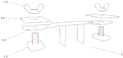
Fig. 1 is a partial top structural view of a fabricated partition keel frame according to embodiment 1 of the invention;
fig. 2 is a partial structural view of the middle part of the assembled partition keel frame provided in embodiment 1 of the invention;
fig. 3 is a partial structural view of the bottom of an assembled partition keel frame according to embodiment 1 of the invention;
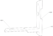
FIG. 4 is a schematic view of the top mount 3 of FIG. 1;
fig. 5 is a structural schematic view of the connecting and fixing structure 1 for fixing top adjacent keels in fig. 1;
fig. 6 is a schematic structural view of the connecting and fixing structure 1 for fixing adjacent cross keels and vertical keels in fig. 1;
FIG. 7 is a schematic structural view of a leveling member 1-1 of the connection fixing structure 1 in FIG. 5 or FIG. 6;
FIG. 8 is a schematic front view of the leveling member 1-1 of FIG. 7;
FIG. 9 is a schematic structural view of a connecting member 1-2 of the connecting and fixing structure 1 of FIG. 5;
FIG. 10 is a schematic structural view of a connecting member 1-2 of the connecting and fixing structure 1 of FIG. 6;
FIG. 11 is a schematic end view of the bottom fixing member 4 of FIG. 3;
fig. 12 is a schematic view of a partition wall according to embodiment 2 of the present invention;
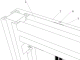
FIG. 13 is a schematic view of the installation of wall panel 7 of the partition wall of example 2 of the present invention;
FIG. 14 is a schematic view of the structure of the connecting block 5 in FIG. 13;
FIG. 15 is a partial schematic view of the partition wall of FIG. 12;
in the figure:
1. connecting and fixing structures; 1-1, leveling members; 1-1-1, clamping sheet; 1-1-2, adjusting rod; 1-1-3, cutting corners; 1-1-4, an auxiliary structure; 1-2, connecting pieces; 1-2-1, positioning holes; 1-2-2, a containing groove; 1-2-3, a limiting sheet; 1-3, a fixing member; 1-4, a gasket;
2. a keel;
3. a top mount; 3-1, L-shaped clamping sheets; 3-1-1, flanging; 3-2, connecting sheets; 3-2-1, flanging; 3-3, hoisting the structure;
4. a bottom fixture; 4-1, convex; 4-2, a groove;
5. connecting the sliding block; 5-1, a convex part; 5-2, a clamping part;
6. a wall panel clamping structure;
7. a wall panel.
Detailed Description
In order to make those skilled in the art better understand the technical solution of the present invention, the following description is made clearly and completely in conjunction with the accompanying drawings in the embodiments of the present invention, and it is obvious that the described embodiments are only a part of the present invention, and not all embodiments. All other embodiments obtained by a person skilled in the art based on examples in the present invention shall fall within the scope of protection of the present invention without making creative efforts.
In the description of the present embodiment, the terms "upper", "lower", "left", "right", and the like indicate orientations or positional relationships based on those shown in the drawings, and are only for convenience in describing the present invention and simplifying the description, but do not indicate or imply that the referred device or element must have a specific orientation, be constructed in a specific orientation, and be operated, and thus, should not be construed as limiting the present invention.
The embodiments and features of the embodiments in the present application may be combined with each other without conflict.
Example 1
As shown in fig. 1 to 11, there is provided an embodiment of a fabricated partition keel frame of the present invention, comprising: the keel structure comprises a plurality of keels 2 with axial T-shaped through grooves formed in installation surfaces, connecting and fixing structures 1 between adjacent keels 2, a bottom fixing piece 4 fixed to the ground and a top fixing piece 3 fixed to the top surface;
the bottom fixing piece 4 is provided with a structure which is clamped with the bottom transverse keel 2 and the vertical frame keel 2; the top fixing piece 3 is provided with a structure clamped with the top cross keel 2;
the connection fixing structure 1 includes: leveling members 1-1, connecting members 1-2 and fixing members 1-3; the leveling component 1-1 comprises an adjusting rod 1-1-2 and a clamping sheet 1-1-1 fixed at one end of the adjusting rod; positioning holes 1-2-1 are formed at two end parts of the connecting piece;
the clamping sheet 1-1-1 of the leveling member 1-1 is clamped in a large groove of the T-shaped through groove, the connecting piece 1-2 is arranged at the joint of the adjacent keels 2, the adjusting rod 1-1-2 of the leveling member 1-1 penetrates through the positioning hole 1-2-1, and the fixing member 1-3 is fixed on the adjusting rod 1-1-2.
Assembled partition wall fossil fragments frame in this embodiment, its top cross keel 2, bottom cross keel 2, vertical frame fossil fragments 2 all adopt the joint mode fixed, adjacent fossil fragments 2 adopt to connect fixed knot to construct and fix, except the T shape that sets up in advance on fossil fragments 2 leads to the groove, in the installation, need not process other holes on the fossil fragments, groove isotructure, fossil fragments frame structure can change in a flexible way, fossil fragments frame structure changes or dismantles the back, fossil fragments 2 that pull down can used repeatedly, the structure of all fossil fragments 2 can be unanimous in the fossil fragments frame, only cut length difference, make things convenient for keeping and supporting of fossil fragments.
It should be noted that the connecting and fixing structure 1 in this embodiment may be used for connecting and fixing the adjacent cross runners 2 and the mullions 2, and may also be used for fixing the top two adjacent cross runners 2 and the mullion 2 located therebetween.
Referring to fig. 1, the upper connecting and fixing structure 1 is located at the top, namely, the connecting and fixing structure for fixing two adjacent cross keels 2 and the vertical keel 2 located between the two cross keels is the connecting and fixing structure, the structure composition is shown in fig. 5 and 7-9, by clamping the clamping sheet 1-1-1 into the big groove of the T-shaped through groove of the keel 2, the installation of two leveling members 1-1 in the T-shaped through grooves of two top cross keels 2 is realized, then two adjusting rods 1-1-2 are respectively inserted into positioning holes 1-2-1 at two ends of a connecting piece 1-2, at the moment, the structure of the connecting piece 1-2 is as shown in figure 9, the connection of two top cross keels 2 and the vertical frame keel 2 between them is realized by connectors 1-2, then, the fixing member 1-3 is fixed to the adjusting lever 1-1-2. Wherein, the spacing pieces 1-2-3 are used for supporting and spacing the vertical frame keel 2 so as to be convenient for installation.
With reference to the lower connection and fastening arrangement 1 in fig. 1, as well as the connection and fastening arrangement 1 in fig. 2 and 3, the fixation of the adjacent cross keels 2 and the vertical keels 2 is realized, the structure composition of which is shown in figures 6-8 and 10, the installation of two leveling members 1-1 in the T-shaped through grooves of two adjacent transverse keels 2 and vertical keels is realized by clamping the clamping sheets 1-1-1 into the large grooves of the T-shaped through grooves of the keels 2, and then two adjusting rods 1-1-2 are respectively inserted into the positioning holes 1-2-1 at the two ends of the connecting piece 1-2, at the moment, the connecting piece 1-2 is a corner connecting piece as shown in figure 10, the connection of the adjacent cross keel 2 and the vertical keel 2 is realized through the corner connecting piece, then, the fixing member 1-3 is fixed to the adjusting lever 1-1-2.
By adopting the connecting and fixing structure 1, the connection of different keels 2 at any position can be realized, the installation and the maintenance are convenient, the rapid assembly of the keels 2 is realized, and the assembly efficiency of the keel frame is improved; the installation can be carried out without professional technicians, so that the number of constructors is relatively reduced, and the labor cost is reduced; after the keel frame is changed or disassembled, the disassembled keel 2 can be reused, and excessive decorating material garbage can not be generated; the structures of the keels 2 in different installation directions can be consistent, and only the difference of the cutting lengths is needed, so that the keels are convenient to store and match.
In this embodiment the axial position of the fixation member 1-3 fixed to the adjustment rod 1-1-2 is adjustable. The fixing members 1-3 are fixed on the adjusting rods 1-1-2 at different positions, so that the installation height of the cross keel 2 can be adjusted in a small range, for example, when one cross keel is connected between two vertical keels, the cross keel is not completely parallel to the ground when being installed, and at the moment, the position of the fixing members 1-3 at the two ends of the cross keel fixed on the adjusting rods 1-1-2 is adjusted, so that the cross keel can be leveled (the cross keel is parallel to the ground and is perpendicular to the two vertical keels connected with the cross keel).
Referring to fig. 5 and 6, the coupling fixing structure 1 in the present embodiment further includes spacers 1 to 4, and the spacers 1 to 4 are installed between the coupling members 1 to 2 and the fixing members 1 to 3. When the connecting piece is the corner connecting piece in fig. 6, the corner connecting piece is installed in the T-shaped through groove, and the gaskets 1-4 are installed between the end face provided with the T-shaped through groove and the fixing members 1-3. The distance between the gasket 1-4 and the clamping sheet 1-1-1 is adjusted by adjusting the mounting position of the fixing member 1-3 on the adjusting rod 1-1-2, so that the mounting height of the cross keel 2 is adjusted.
In the embodiment, the length of the clamping sheet 1-1-1 is greater than the width of the small groove of the T-shaped through groove and less than or equal to the width of the large groove of the T-shaped through groove, the width of the clamping sheet 1-1-1 is less than the width of the small groove of the T-shaped through groove, the clamping sheet is installed in the T-shaped through groove along the width direction of the width 1-1-1, and the length direction of the clamping sheet 1-1-1 is clamped into the large groove of the T-shaped through groove through rotation. Preferably, the snap sheet 1-1-1 is processed with two cutting angles 1-1-3 at intervals. So that the clamping sheet 1-1-1 can be conveniently screwed into the large groove of the T-shaped groove of the keel 2 in the length direction when the leveling component 1-1 is installed.
As an alternative, the snap sheet 1-1-1 is a spring sheet capable of generating large elastic deformation, the snap sheet 1-1-1 passes through the small groove of the T-shaped through groove during elastic deformation and then is snapped into the large groove in the T-shaped through groove, for example, a snap spring is arranged in the middle of the length direction of the snap sheet 1-1-1, and the snap sheets 1-1-1 at the two ends are compressed and extended through the snap spring.
Referring to fig. 6 and 10, in the present embodiment, when the adjacent cross keels 2 and the adjacent vertical keels 2 are connected, at least one side end surface of the corner connector adjacent to the snap pieces 1-1-1 is provided with an accommodating groove 1-2-2, the accommodating groove 1-2-2 penetrates through the corner connector along the groove width direction of the T-shaped through groove, the groove width of the accommodating groove 1-2-2 is matched with the width of the snap pieces 1-1-1, so that all or part of the snap pieces 1-1 are accommodated in the accommodating groove 1-2-2, and when the fixing member 1-3 is mounted on the adjusting rod 1-1-2, the adjusting rod 1-1-2 is prevented from driving the snap pieces 1-1-1 to rotate or move.
As an alternative mode, the containing groove can also be arranged on the end face of the clamping sheet 1-1-1 contacted with the corner connecting piece, the containing groove is arranged in the length direction of the clamping sheet 1-1 and penetrates through the width direction of the clamping sheet, the containing groove is consistent with the penetrating direction of the T-shaped through groove of the keel 2, the groove width of the containing groove is matched with the width of the corner connecting piece, all or part of the corner connecting piece is contained in the containing groove in the T-shaped groove of the keel 2 at one side, and when the fixing member 1-3 is installed, the adjusting rod 1-1-2 is prevented from driving the clamping sheet 1-1-1 to rotate or move.
In this embodiment, the end of the adjustment rod 1-1-1 is provided with an auxiliary structure 1-1-4 for facilitating the fastening of the fastening tool. In this example, the auxiliary structure 1-1-4 is an inner hexagonal groove disposed at an end of the adjusting rod 1-1-1, and when the fixing member 1-3 is installed or adjusted, when the engagement piece 1-1-1 of the leveling member 1-1 is disengaged from the receiving groove 1-2-2 and rotated or moved, a hexagonal wrench may be inserted into the inner hexagonal groove, and when the fixing member 1-3 is installed, the leveling member 1-1 is in a relatively fixed state, thereby facilitating installation.
Alternatively, a flat structure may be provided at the end of the adjusting rod 1-1-1, and when the fixing member 1-3 is mounted, a tool such as a pliers or a wrench may be used to clamp the flat structure, so that the leveling member 1-1 is in a relatively fixed state, thereby facilitating the mounting.
In this embodiment, the adjusting rod 1-1-2 is a screw, and the fixing member 1-3 is a nut.
As one or alternative, the adjusting rod 1-1-2 can be provided with different clamping positions in the axial direction, and the fixing member 1-3 can be a clamping member such as a clamp spring.
In this embodiment, the fixing members 1-3 are wing nuts, so that installation and adjustment can be accomplished without using tools such as a wrench.
Referring to fig. 4, the top fixing member 3 includes an L-shaped clip 3-1 having an L-shaped bent structure, a connecting piece 3-2 having an L-shaped bent structure at one end, and a hoisting structure 3-3 hoisted to a roof; the L-shaped connecting sheet 3-1 is connected with the L-shaped bending structure end of the connecting sheet 3-2, and the turned edge 3-1-1 and the turned edge 3-2-1 of the L-shaped bending structures of the L-shaped connecting sheet and the L-shaped bending structure are clamped and installed in the large groove of the T-shaped through groove from two sides; the hoisting structure 3-3 is connected with the other end of the connecting sheet 3-2. In the embodiment, the connecting sheet is a U-shaped connecting sheet; the other end of the hoisting structure 3-3 may be fixed to the roof by means of anchor bolts or the like.
Referring to fig. 3 and 11, the bottom fixing member 4 is a strip-shaped frame structure having a protrusion 4-1 at the middle and grooves 4-2 at both sides of the protrusion 4-1. The self-tapping screw is fixed on the ground through the protrusions 4-1, and in order to facilitate the fixing of the self-tapping screw, the protrusions 4-1 are provided with countersunk grooves so as to facilitate the fixing of the self-tapping screw. A
The mounting means of fossil fragments in this embodiment can be, installs bottom mounting 4 earlier, installs the fossil fragments 2 that are in outside frame department again, and bottom cross keel 2, top cross keel 2 and the vertical frame fossil fragments that all are connected with the two promptly can be according to from left to right or from the right side to left order install every fossil fragments frame unit in proper order, then can be according to the demand, the nimble installation of carrying out cross keel 2 and vertical keel 2.
It should be noted that, in order to facilitate installation of the whole keel frame, the keel 2 in this embodiment may be made of an aluminum alloy profile. Because 4 sides of aluminum alloy ex-trusions all have T type logical groove generally, consequently, when carrying out the installation of fossil fragments frame, only need with aluminum alloy ex-trusions cut can, facilitate the use. The keel 2 of the embodiment can also be of other structures or materials, as long as a T-shaped through groove is formed at the joint of the adjacent keels 2, so that the keel frame in the embodiment can be installed.
Example 2
As shown in fig. 12-15, there is provided an embodiment of the partition wall of the present invention, which comprises the fabricated partition wall keel frame of example 1, the connecting blocks 5 fitted into T-shaped through grooves of the keel in the fabricated partition wall keel frame, the wall panel clamping structures 6 fixed to the plurality of connecting blocks, the wall panels 7; the connecting slide block 5 can slide in the T-shaped through groove; wallboard clamping structure 6 is used for the fixed wallboard of centre gripping.
In the partition wall of the embodiment, after the wall plate 7 is clamped and fixed on the wall plate clamping structure 6, the connecting sliding block 5 can slide along the T-shaped through groove, so that the wall plate 7 can also slide, and the position of the wall plate 7 can be adjusted; wallboard 7 passes through wallboard clamping structure 6 and link block 5 and realizes with the installation of fossil fragments, when wallboard 7 or fossil fragments 2 are dismantled to needs, wallboard 7 and the equal used repeatedly of fossil fragments 6 that pull down have improved the utilization ratio of resource.
Referring to fig. 13 and 14, the connecting slide 5 is a structure with a boss 5-1 and a clamping portion 5-2, the boss 5-1 is used for fixedly connecting with the wallboard clamping structure 6, and in the embodiment, the middle of the wallboard clamping structure 6 is fixed on the boss 5-1 by a self-tapping screw.
In this embodiment, the connecting slide blocks 5 are installed in the T-shaped through grooves of the cross keels, i.e. the clamping portions 5-2 are installed in the large grooves of the T-shaped through grooves, and the wallboard clamping structures 6 are vertically fixed to the protrusions 5-1 of the connecting slide blocks 5.
Referring to fig. 14, the upper clamping portion 5-2 is longer, because when the connecting slide block 5 is installed in the T-shaped through groove of the cross keel, the connecting slide block 5 in the T-shaped through groove will deflect downward due to the gravity of the wall plate clamping structure 6 and the wall plate 7, and the upper clamping portion 5-2 is longer in order to ensure that the connecting slide block 5 is in the T-shaped through groove.
Referring to fig. 15, the middle part of the wallboard clamping structure 6 is connected with the connecting slide block 5, and clamping grooves are arranged on two sides of the wallboard clamping structure 6 so as to complete clamping and splicing of wallboards 7 on two sides of the wallboard clamping structure.
Finally, it is to be understood that the above embodiments are merely exemplary embodiments taken to illustrate the principles of the present invention, which is not intended to be limiting. It will be apparent to those skilled in the art that various changes and modifications can be made therein without departing from the spirit and scope of the invention, and these changes and modifications are to be considered as within the scope of the invention.
Claims (10)
1. An assembled partition keel frame, comprising: the keel structure comprises a plurality of keels, a connecting and fixing structure, a bottom fixing piece and a top fixing piece, wherein the keels are provided with axial T-shaped through grooves on installation surfaces;
the bottom fixing piece is provided with a structure clamped with the bottom transverse keel and the vertical frame keel; the top fixing piece is provided with a structure clamped with the top transverse keel;
the connection fixing structure includes: leveling members, connecting members and fixing members; the leveling member comprises an adjusting rod and a clamping piece fixed at one end of the adjusting rod; positioning holes are formed in the two end parts of the connecting piece;
the joint piece joint of leveling member is received in the big groove that the T type led to the groove, the connecting piece is installed in adjacent fossil fragments junction, the regulation pole of leveling member passes the locating hole, fixed component is fixed on adjusting the pole.
2. The fabricated partition grid frame of claim 1, wherein the axial position of the securing member secured to the adjustment rod is adjustable.
3. The fabricated partition grid frame of claim 1, wherein the connectors are corner connectors connecting adjacent cross and cross runners.
4. The fabricated partition keel frame of claim 3, wherein said connecting and fixing structure further comprises a gasket, said connecting member being fitted into said T-shaped through slot, said gasket being fitted between an end surface of said T-shaped through slot and said fixing member.
5. The fabricated partition grid frame of claim 1, wherein the length of the snap tab is greater than the small groove width of the T-channel, less than or equal to the large groove width of the T-channel, and the width of the snap tab is less than the small groove width of the T-channel; two cutting angles are processed at intervals on the clamping piece.
6. The fabricated partition wall keel frame of claim 1, wherein at least one side end surface of said corner connector adjacent to said snap tab is provided with a receiving slot, said receiving slot extending through said corner connector in the slot width direction of said T-shaped through slot, the slot width of said receiving slot matching the width of said snap tab.
7. A fabricated partition keel frame according to claim 1 or 6, wherein the ends of the adjusting bars are provided with auxiliary structures facilitating the fastening of fastening tools.
8. The fabricated partition keel frame of claim 1, wherein said top fixture comprises an L-shaped clip with an L-shaped bent structure, a connecting piece with an L-shaped bent structure at one end, a hoisting structure for hoisting to a roof; the L-shaped connecting sheet is connected with the L-shaped bending structure end of the connecting sheet, and flanges of the L-shaped bending structures of the L-shaped connecting sheet and the connecting sheet are clamped and mounted in the large groove of the T-shaped through groove from two sides; the hoisting structure is connected with the other end of the connecting sheet.
9. A partition comprising an assembled partition keel frame according to any one of claims 1-8, connecting blocks mounted in T-shaped through slots in the keel in the assembled partition keel frame, wall panel holding structures secured to a plurality of the connecting blocks, wall panels; the connecting sliding block can slide in the T-shaped through groove; the wallboard clamping structure is used for clamping and fixing the wallboard.
10. The partition of claim 9 wherein the connector blocks are mounted in T-shaped channels in the cross runners and the panel clamp structure is vertically secured to a plurality of the connector blocks.
Priority Applications (1)
| Application Number | Priority Date | Filing Date | Title |
|---|---|---|---|
| CN202011279073.0A CN112376742A (en) | 2020-11-16 | 2020-11-16 | Assembled partition wall fossil fragments frame and partition wall |
Applications Claiming Priority (1)
| Application Number | Priority Date | Filing Date | Title |
|---|---|---|---|
| CN202011279073.0A CN112376742A (en) | 2020-11-16 | 2020-11-16 | Assembled partition wall fossil fragments frame and partition wall |
Publications (1)
| Publication Number | Publication Date |
|---|---|
| CN112376742A true CN112376742A (en) | 2021-02-19 |
Family
ID=74585394
Family Applications (1)
| Application Number | Title | Priority Date | Filing Date |
|---|---|---|---|
| CN202011279073.0A Pending CN112376742A (en) | 2020-11-16 | 2020-11-16 | Assembled partition wall fossil fragments frame and partition wall |
Country Status (1)
| Country | Link |
|---|---|
| CN (1) | CN112376742A (en) |
Cited By (1)
| Publication number | Priority date | Publication date | Assignee | Title |
|---|---|---|---|---|
| WO2024011866A1 (en) * | 2022-07-13 | 2024-01-18 | 北新集团建材股份有限公司 | Wall mounting frame structure and corner snap-fitting member |
-
2020
- 2020-11-16 CN CN202011279073.0A patent/CN112376742A/en active Pending
Cited By (1)
| Publication number | Priority date | Publication date | Assignee | Title |
|---|---|---|---|---|
| WO2024011866A1 (en) * | 2022-07-13 | 2024-01-18 | 北新集团建材股份有限公司 | Wall mounting frame structure and corner snap-fitting member |
Similar Documents
| Publication | Publication Date | Title |
|---|---|---|
| CN112376742A (en) | Assembled partition wall fossil fragments frame and partition wall | |
| CN214144252U (en) | Assembled partition wall fossil fragments frame and partition wall | |
| JP2013249579A (en) | Solar cell module fixing structure and method of fixing solar cell module | |
| CN110805196B (en) | Suspension rod-free ceiling structure | |
| JP3455210B1 (en) | Mounting frame for solar cell panel and method of assembling the same | |
| CN214090494U (en) | Assembled partition wall fossil fragments mounting | |
| JP2003239482A (en) | Solar battery panel mounting stand and method for assembling the same | |
| CN113417391A (en) | Stepless regulation type fixing structure for wall board | |
| CN215483996U (en) | Light firm suspended ceiling | |
| CN215253869U (en) | Assembled furred ceiling device and decorate furred ceiling | |
| JP3202583U (en) | Support structure for photovoltaic panels | |
| CN220139158U (en) | Portable channel installation fixing device | |
| CN219909567U (en) | Assembled furred ceiling | |
| CN217811884U (en) | Hanging aluminum alloy grid | |
| CN211776163U (en) | Assembled clean operating room | |
| CN214412121U (en) | Electric bridge structure of building | |
| CN215858456U (en) | Stepless regulation type fixing structure for wall board | |
| CN216641218U (en) | Wall mounting structure is maked somebody a mere figurehead to ready-package that wallboard reutilization can | |
| CN218233931U (en) | Indoor dry-hanging stone curtain wall mounting structure | |
| CN218149146U (en) | Curtain wall connecting structure | |
| CN220598874U (en) | Top surface large-span overlength aluminium grid | |
| CN215368095U (en) | Externally-mounted rhombic curtain wall plate structure | |
| CN212224385U (en) | Keel structure for suspended ceiling | |
| CN220504245U (en) | Stone plate connecting device of stone curtain wall | |
| CN215759920U (en) | Extrusion material ceiling structure |
Legal Events
| Date | Code | Title | Description |
|---|---|---|---|
| PB01 | Publication | ||
| PB01 | Publication | ||
| SE01 | Entry into force of request for substantive examination | ||
| SE01 | Entry into force of request for substantive examination |