CN112355036A - Cast iron production waste residue processing apparatus with filtering capability - Google Patents
Cast iron production waste residue processing apparatus with filtering capability Download PDFInfo
- Publication number
- CN112355036A CN112355036A CN202011310639.1A CN202011310639A CN112355036A CN 112355036 A CN112355036 A CN 112355036A CN 202011310639 A CN202011310639 A CN 202011310639A CN 112355036 A CN112355036 A CN 112355036A
- Authority
- CN
- China
- Prior art keywords
- gear
- cast iron
- machine body
- iron production
- rotating shaft
- Prior art date
- Legal status (The legal status is an assumption and is not a legal conclusion. Google has not performed a legal analysis and makes no representation as to the accuracy of the status listed.)
- Withdrawn
Links
Images


Classifications
-
- B—PERFORMING OPERATIONS; TRANSPORTING
- B09—DISPOSAL OF SOLID WASTE; RECLAMATION OF CONTAMINATED SOIL
- B09B—DISPOSAL OF SOLID WASTE
- B09B3/00—Destroying solid waste or transforming solid waste into something useful or harmless
-
- B—PERFORMING OPERATIONS; TRANSPORTING
- B01—PHYSICAL OR CHEMICAL PROCESSES OR APPARATUS IN GENERAL
- B01D—SEPARATION
- B01D46/00—Filters or filtering processes specially modified for separating dispersed particles from gases or vapours
- B01D46/10—Particle separators, e.g. dust precipitators, using filter plates, sheets or pads having plane surfaces
-
- B—PERFORMING OPERATIONS; TRANSPORTING
- B02—CRUSHING, PULVERISING, OR DISINTEGRATING; PREPARATORY TREATMENT OF GRAIN FOR MILLING
- B02C—CRUSHING, PULVERISING, OR DISINTEGRATING IN GENERAL; MILLING GRAIN
- B02C13/00—Disintegrating by mills having rotary beater elements ; Hammer mills
- B02C13/02—Disintegrating by mills having rotary beater elements ; Hammer mills with horizontal rotor shaft
- B02C13/06—Disintegrating by mills having rotary beater elements ; Hammer mills with horizontal rotor shaft with beaters rigidly connected to the rotor
-
- B—PERFORMING OPERATIONS; TRANSPORTING
- B02—CRUSHING, PULVERISING, OR DISINTEGRATING; PREPARATORY TREATMENT OF GRAIN FOR MILLING
- B02C—CRUSHING, PULVERISING, OR DISINTEGRATING IN GENERAL; MILLING GRAIN
- B02C13/00—Disintegrating by mills having rotary beater elements ; Hammer mills
- B02C13/26—Details
- B02C13/282—Shape or inner surface of mill-housings
- B02C13/284—Built-in screens
-
- B—PERFORMING OPERATIONS; TRANSPORTING
- B02—CRUSHING, PULVERISING, OR DISINTEGRATING; PREPARATORY TREATMENT OF GRAIN FOR MILLING
- B02C—CRUSHING, PULVERISING, OR DISINTEGRATING IN GENERAL; MILLING GRAIN
- B02C13/00—Disintegrating by mills having rotary beater elements ; Hammer mills
- B02C13/26—Details
- B02C13/30—Driving mechanisms
-
- B—PERFORMING OPERATIONS; TRANSPORTING
- B02—CRUSHING, PULVERISING, OR DISINTEGRATING; PREPARATORY TREATMENT OF GRAIN FOR MILLING
- B02C—CRUSHING, PULVERISING, OR DISINTEGRATING IN GENERAL; MILLING GRAIN
- B02C21/00—Disintegrating plant with or without drying of the material
-
- B—PERFORMING OPERATIONS; TRANSPORTING
- B02—CRUSHING, PULVERISING, OR DISINTEGRATING; PREPARATORY TREATMENT OF GRAIN FOR MILLING
- B02C—CRUSHING, PULVERISING, OR DISINTEGRATING IN GENERAL; MILLING GRAIN
- B02C23/00—Auxiliary methods or auxiliary devices or accessories specially adapted for crushing or disintegrating not provided for in preceding groups or not specially adapted to apparatus covered by a single preceding group
- B02C23/02—Feeding devices
-
- B—PERFORMING OPERATIONS; TRANSPORTING
- B02—CRUSHING, PULVERISING, OR DISINTEGRATING; PREPARATORY TREATMENT OF GRAIN FOR MILLING
- B02C—CRUSHING, PULVERISING, OR DISINTEGRATING IN GENERAL; MILLING GRAIN
- B02C23/00—Auxiliary methods or auxiliary devices or accessories specially adapted for crushing or disintegrating not provided for in preceding groups or not specially adapted to apparatus covered by a single preceding group
- B02C23/04—Safety devices
-
- B—PERFORMING OPERATIONS; TRANSPORTING
- B02—CRUSHING, PULVERISING, OR DISINTEGRATING; PREPARATORY TREATMENT OF GRAIN FOR MILLING
- B02C—CRUSHING, PULVERISING, OR DISINTEGRATING IN GENERAL; MILLING GRAIN
- B02C23/00—Auxiliary methods or auxiliary devices or accessories specially adapted for crushing or disintegrating not provided for in preceding groups or not specially adapted to apparatus covered by a single preceding group
- B02C23/08—Separating or sorting of material, associated with crushing or disintegrating
- B02C23/10—Separating or sorting of material, associated with crushing or disintegrating with separator arranged in discharge path of crushing or disintegrating zone
-
- B—PERFORMING OPERATIONS; TRANSPORTING
- B02—CRUSHING, PULVERISING, OR DISINTEGRATING; PREPARATORY TREATMENT OF GRAIN FOR MILLING
- B02C—CRUSHING, PULVERISING, OR DISINTEGRATING IN GENERAL; MILLING GRAIN
- B02C4/00—Crushing or disintegrating by roller mills
- B02C4/02—Crushing or disintegrating by roller mills with two or more rollers
- B02C4/08—Crushing or disintegrating by roller mills with two or more rollers with co-operating corrugated or toothed crushing-rollers
-
- B—PERFORMING OPERATIONS; TRANSPORTING
- B02—CRUSHING, PULVERISING, OR DISINTEGRATING; PREPARATORY TREATMENT OF GRAIN FOR MILLING
- B02C—CRUSHING, PULVERISING, OR DISINTEGRATING IN GENERAL; MILLING GRAIN
- B02C4/00—Crushing or disintegrating by roller mills
- B02C4/28—Details
- B02C4/286—Feeding devices
-
- B—PERFORMING OPERATIONS; TRANSPORTING
- B02—CRUSHING, PULVERISING, OR DISINTEGRATING; PREPARATORY TREATMENT OF GRAIN FOR MILLING
- B02C—CRUSHING, PULVERISING, OR DISINTEGRATING IN GENERAL; MILLING GRAIN
- B02C4/00—Crushing or disintegrating by roller mills
- B02C4/28—Details
- B02C4/42—Driving mechanisms; Roller speed control
-
- B—PERFORMING OPERATIONS; TRANSPORTING
- B08—CLEANING
- B08B—CLEANING IN GENERAL; PREVENTION OF FOULING IN GENERAL
- B08B15/00—Preventing escape of dirt or fumes from the area where they are produced; Collecting or removing dirt or fumes from that area
- B08B15/04—Preventing escape of dirt or fumes from the area where they are produced; Collecting or removing dirt or fumes from that area from a small area, e.g. a tool
-
- B—PERFORMING OPERATIONS; TRANSPORTING
- B09—DISPOSAL OF SOLID WASTE; RECLAMATION OF CONTAMINATED SOIL
- B09B—DISPOSAL OF SOLID WASTE
- B09B5/00—Operations not covered by a single other subclass or by a single other group in this subclass
-
- B—PERFORMING OPERATIONS; TRANSPORTING
- B02—CRUSHING, PULVERISING, OR DISINTEGRATING; PREPARATORY TREATMENT OF GRAIN FOR MILLING
- B02C—CRUSHING, PULVERISING, OR DISINTEGRATING IN GENERAL; MILLING GRAIN
- B02C2201/00—Codes relating to disintegrating devices adapted for specific materials
- B02C2201/06—Codes relating to disintegrating devices adapted for specific materials for garbage, waste or sewage
Abstract
The invention belongs to the technical field of cast iron waste residue treatment devices, and particularly discloses a cast iron production waste residue treatment device with a filtering function, which comprises a machine body, stirring fragments and a recovery box, wherein a feeding cylinder is installed at the top of the machine body, a cover is installed above the feeding cylinder, a first chute is reserved on the inner side of the feeding cylinder, a first sliding block is connected to the inner wall of the first chute, a first gear is installed on the inner side of the machine body, a first rotating shaft is connected to the middle position of the first gear, a second gear is installed on the outer wall of the first gear, the stirring fragments are installed below the first gear, a movable rod is connected to the middle position of the stirring fragments, and a second rotating shaft is connected to the outer wall of the movable rod. This cast iron production waste residue processing apparatus with filtering capability can carry out quick pan feeding, and the leakproofness is stronger, and efficiency is higher, stirs garrulous more even, and the recovery processing of being convenient for clears up more facility, ensures that dust and impurity can not drift away more environmental protection.
Description
Technical Field
The invention relates to the technical field of cast iron waste residue treatment devices, in particular to a cast iron production waste residue treatment device with a filtering function.
Background
The cast iron waste residue treatment device is a device for stirring, crushing and recycling waste materials in cast iron production, casting is an extremely complex production process flow which adopts various raw and auxiliary materials and is smelted through metallurgy, material consumption which is not avoided is inevitably generated in the cast iron production process, waste residue materials basically fall off below a processing table surface automatically, and regular cleaning is needed in the processing process. Therefore, the cast iron production waste residue treatment device with the filtering function is designed.
In Chinese invention patent CN201921301827.0, a waste residue treatment device for iron and steel plants, comprises a settling tank, a crushing tank is arranged at the top of the settling tank, a first motor is fixedly arranged at the top of the crushing tank, an output shaft of the first motor penetrates through the top of the crushing tank and is provided with a fixed sleeve, a crushing rod is welded on the side surface of the fixed sleeve, and a plurality of blades are welded on the side surface of the crushing rod. The sealing performance is poor, the safety is low, the stirring efficiency is low, the later recovery treatment is inconvenient, the filter screen is not convenient to clean, the practicability is poor, the transfer is inconvenient, the stability is poor, the environmental protection is poor, the service life is short, rapid feeding is needed, the sealing performance is stronger, the material stirring is more uniform, the volume of the material is further reduced, the recovery treatment is convenient, the recovery box is convenient to clean in time, the filter screen is more convenient to clean, the practicability of the recovery box is improved, the transfer is more convenient, the friction force between the machine body and the ground can be increased by the non-slip mat, the non-slip mat is more stable, dust and impurities generated during stirring can be sucked into the purification box, the dust and the impurities can not fall out, the environment is more environment-friendly, the treatment effect of waste residues is better, the purification net can be timely disassembled and cleaned, and the cleanness of the purification net is ensured, is favorable for strengthening the purification effect.
In order to solve the problems, a novel cast iron production waste residue treatment device with a filtering function is provided.
Disclosure of Invention
The invention aims to provide a cast iron production waste residue treatment device with a filtering function, and aims to solve the problems that similar products in the background art are inconvenient to clean a filter screen, poor in practicability, transfer and stability and poor in environmental friendliness.
In order to achieve the purpose, the invention provides the following technical scheme: a cast iron production waste residue treatment device with a filtering function comprises a machine body, a stirring piece and a recycling box, wherein a charging barrel is installed at the top of the machine body, a cover is installed above the charging barrel, a first sliding groove is reserved on the inner side of the charging barrel, a first sliding block is connected to the inner wall of the first sliding groove, a first gear is installed on the inner side of the machine body, a first rotating shaft is connected to the middle position of the first gear, a second gear is installed on the outer wall of the first gear, the stirring piece is installed below the first gear, a movable rod is connected to the middle position of the stirring piece, a second rotating shaft is connected to the outer wall of the movable rod, the recycling box is installed below the machine body, a filter screen is installed on the inner side of the recycling box, a second sliding groove is reserved on each of the two sides of the recycling box, a second sliding groove is connected to the inner wall of the second sliding groove, a supporting rod is installed on, and the stopper is installed to the below of bracing piece, the universal wheel is installed to the inboard of stopper, and the intermediate position of universal wheel is connected with the third pivot, the lifter is installed to the bottom of collection box, and the below of lifter installs the slipmat, the lifter both sides all reserve has the third spout, and the inner wall of third spout is connected with the third slider, the outer wall connection of organism has the dust absorption pipe, and installs the blade in the below of dust absorption pipe to the intermediate position of blade is connected with the fourth pivot, the purifying box is installed to the bottom of blade, and the inboard of purifying box is connected with out the dirt pipe, go out the below of dirt pipe and install the purification net, and the both sides of purification net all are fixed with the fixture block.
Preferably, the cover forms a sliding structure through the first sliding block and the first sliding groove, and the cover is connected with the feeding barrel in a nested manner.
Preferably, the first gear and the machine body form a rotating structure through the first rotating shaft, and the first gear and the second gear are in meshed connection.
Preferably, the stirring fragments are distributed on the outer side of the movable rod at equal intervals, and the movable rod and the machine body form a rotating structure through a second rotating shaft.
Preferably, the recycling bin forms a sliding structure through the second sliding block and the second sliding groove, and is made of stainless steel.
Preferably, be the block between filter screen and the collection box and be connected, and be threaded connection between collection box and the bracing piece.
Preferably, the universal wheel forms rotating-structure with the bracing piece through the third pivot, and is connected for the block between universal wheel and the stopper.
Preferably, the central axis of the lifting rod coincides with the central axis of the non-slip mat, and the lifting rod and the third sliding groove form a lifting structure through the third sliding block.
Preferably, the blade forms a rotating structure with the dust collection pipe through the fourth rotating shaft, and the dust collection pipe is tightly attached to the machine body.
Preferably, be the block between purification net and the purifying box and be connected, and be threaded connection between purification net and the fixture block.
Compared with the prior art, the invention has the beneficial effects that:
1. the cast iron production waste residue treatment device with the filtering function can be used for quickly feeding materials, can realize the sealing property of a machine body, avoids unnecessary damage caused by splashing of waste residues during crushing, and can be used for extruding and crushing materials through the relative rotation of the first gear and the second gear, so that the volume of the materials is reduced, the later recovery treatment is facilitated, the secondary crushing work can be performed on the materials, the materials are uniformly crushed, the volume of the materials is further reduced, and the recovery is facilitated;
2. the cast iron production waste residue treatment device with the filtering function can uniformly recover the crushed materials, is convenient for timely cleaning the recycling bin, has larger hardness of stainless steel materials, avoids collision between the materials and the inner wall of the recycling bin, causes deformation and damage of the recycling bin, is convenient for timely cleaning the filter screen, avoids the condition of blocking the filter screen, improves the practicability of the recycling bin, endows the machine body with moving force, enables the machine body to be more convenient to transfer, and can fix the universal wheels by the limiting blocks, avoid the machine body from position deviation and improve the stability of the machine body;
3. this cast iron production waste residue processing apparatus with filtering capability, the slipmat can increase the frictional force on organism and ground, when not needing to remove, can be with the position control of lifter to the position higher than the universal wheel, ensure stable fixing in the original place of organism during operation, can inhale the purifying box with dust and impurity that produce when stirring garrulous in, ensure that dust and impurity can not waft away, environmental protection more when making organism operation, the treatment effect of waste residue is better, can in time dismantle cleanly to the purification net, guarantee the cleanness of purification net, be favorable to strengthening the effect of purification.
Drawings
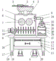
FIG. 1 is a schematic front sectional view of the present invention;
FIG. 2 is a side view of the movable rod of the present invention;
FIG. 3 is an enlarged view of the structure at A in FIG. 1 according to the present invention;
fig. 4 is a front view of the body of the present invention.
In the figure: 1. a body; 2. feeding into a charging barrel; 3. a cover; 4. a first chute; 5. a first slider; 6. a first gear; 7. a first rotating shaft; 8. a second gear; 9. stirring the fragments; 10. a movable rod; 11. a second rotating shaft; 12. a recycling bin; 13. a filter screen; 14. a second chute; 15. a second slider; 16. a support bar; 17. a limiting block; 18. a universal wheel; 19. a third rotating shaft; 20. a lifting rod; 21. a non-slip mat; 22. a third chute; 23. a third slider; 24. a dust collection pipe; 25. a blade; 26. a fourth rotating shaft; 27. a purification box; 28. a dust outlet pipe; 29. a purification net; 30. and (7) clamping blocks.
Detailed Description
The technical solutions in the embodiments of the present invention will be clearly and completely described below with reference to the drawings in the embodiments of the present invention, and it is obvious that the described embodiments are only a part of the embodiments of the present invention, and not all of the embodiments. All other embodiments, which can be derived by a person skilled in the art from the embodiments given herein without making any creative effort, shall fall within the protection scope of the present invention.
Referring to fig. 1-4, the present invention provides a technical solution: a cast iron production waste residue treatment device with a filtering function comprises a machine body 1, a feeding cylinder 2, a cover 3, a first sliding groove 4, a first sliding block 5, a first gear 6, a first rotating shaft 7, a second gear 8, a stirring piece 9, a movable rod 10, a second rotating shaft 11, a recovery box 12, a filter screen 13, a second sliding groove 14, a second sliding block 15, a supporting rod 16, a limiting block 17, a universal wheel 18, a third rotating shaft 19, a lifting rod 20, an anti-slip pad 21, a third sliding groove 22, a third sliding block 23, a dust suction pipe 24, blades 25, a fourth rotating shaft 26, a purification box 27, a dust outlet pipe 28, a purification net 29 and a fixture block 30, wherein the feeding cylinder 2 is installed at the top of the machine body 1, the cover 3 is installed above the feeding cylinder 2, a first sliding groove 4 is reserved on the inner side of the feeding cylinder 2, the inner wall of the first sliding groove 4 is connected with the first sliding block 5, the first gear 6 is installed on the inner side of, a first rotating shaft 7 is connected to the middle position of the first gear 6, a second gear 8 is installed on the outer wall of the first gear 6, a crushing piece 9 is installed below the first gear 6, a movable rod 10 is connected to the middle position of the crushing piece 9, a second rotating shaft 11 is connected to the outer wall of the movable rod 10, a recycling box 12 is installed below the machine body 1, a filter screen 13 is installed on the inner side of the recycling box 12, second sliding grooves 14 are reserved on two sides of the recycling box 12, a second sliding block 15 is connected to the inner wall of each second sliding groove 14, a supporting rod 16 is installed on the outer wall of the recycling box 12, a limiting block 17 is installed below the supporting rod 16, a universal wheel 18 is installed on the inner side of the limiting block 17, a third rotating shaft 19 is connected to the middle position of the universal wheel 18, a lifting rod 20 is installed at the bottom of the recycling box 12, an anti-skid pad 21 is installed below the lifting rod 20, third sliding grooves 22 are reserved on two, and the inner wall of the third chute 22 is connected with a third slide block 23, the outer wall of the machine body 1 is connected with a dust collection pipe 24, a blade 25 is installed below the dust collection pipe 24, the middle position of the blade 25 is connected with a fourth rotating shaft 26, the bottom of the blade 25 is provided with a purification box 27, the inner side of the purification box 27 is connected with a dust outlet pipe 28, a purification net 29 is installed below the dust outlet pipe 28, and two sides of the purification net 29 are both fixed with fixture blocks 30.
Furthermore, the cover 3 and the first sliding chute 4 form a sliding structure through the first sliding block 5, and the cover 3 and the feeding barrel 2 are connected in a nested manner, so that rapid feeding can be performed, the sealing performance of the machine body 1 can be realized, and unnecessary damage caused by splashing of waste residues during crushing is avoided;
furthermore, the first gear 6 and the machine body 1 form a rotating structure through the first rotating shaft 7, and the first gear 6 is in meshed connection with the second gear 8, so that the materials are extruded and crushed through the rotation of the first gear 6 and the second gear 8 in opposite directions, the volume of the materials is reduced, and the later recovery processing is facilitated;
furthermore, the crushing pieces 9 are distributed on the outer side of the movable rod 10 at equal intervals, and the movable rod 10 and the machine body 1 form a rotating structure through the second rotating shaft 11, so that the material can be subjected to secondary crushing work, the material is crushed more uniformly, the volume of the material is further reduced, and the material is convenient to recover;
furthermore, the recycling bin 12 and the second sliding chute 14 form a sliding structure through the second sliding block 15, and the recycling bin 12 is made of stainless steel, so that the crushed materials can be recycled uniformly, the recycling bin 12 can be cleaned in time conveniently, and meanwhile, the hardness of the stainless steel is high, so that the materials are prevented from colliding with the inner wall of the recycling bin 12, and the recycling bin 12 is prevented from being deformed and damaged;
furthermore, the filter screen 13 is connected with the recovery box 12 in a clamping manner, and the recovery box 12 is connected with the support rod 16 in a threaded manner, so that the filter screen 13 can be cleaned in time, the situation that the filter screen 13 is blocked is avoided, and the practicability of the recovery box 12 is improved;
furthermore, the universal wheel 18 and the support rod 16 form a rotating structure through the third rotating shaft 19, and the universal wheel 18 and the limiting block 17 are connected in a clamping manner, so that the moving force is given to the machine body 1, the machine body 1 is more convenient to transfer, meanwhile, the limiting block 17 can fix the universal wheel 18, the machine body 1 is prevented from being shifted, and the stability of the machine body 1 is improved;
furthermore, the central axis of the lifting rod 20 coincides with the central axis of the non-slip mat 21, and the lifting rod 20 forms a lifting structure with the third sliding chute 22 through the third sliding block 23, so that the non-slip mat 21 can increase the friction force between the machine body 1 and the ground, and when the non-slip mat does not need to move, the position of the lifting rod 20 can be adjusted to be higher than the position of the universal wheel 18, so that the machine body 1 is stably fixed in place during working;
furthermore, the blades 25 and the dust suction pipe 24 form a rotating structure through the fourth rotating shaft 26, and the dust suction pipe 24 is tightly attached to the machine body 1, so that dust and impurities generated during crushing can be sucked into the purifying box 27, the dust and the impurities are prevented from falling off, the machine body 1 is more environment-friendly during working, and the treatment effect of waste residues is better;
further, be connected for the block between purification net 29 and the purifying box 27, and be threaded connection between purification net 29 and the fixture block 30, such setting can in time dismantle cleanly to purification net 29, guarantees the cleanness of purification net 29, is favorable to strengthening the effect of purifying.
The working principle is as follows: the use flow of the cast iron production waste residue treatment device with the filtering function comprises the following steps that firstly, a worker moves the machine body 1 to a place where waste residue treatment is needed through the mobility of the universal wheels 18, the universal wheels 18 give moving force to the machine body 1, so that the machine body 1 is more convenient to transfer, after the destination is reached, the universal wheels 18 can be fixed by the limiting blocks 17, the machine body 1 is prevented from deviating in position, the stability of the machine body 1 is improved, then, the worker can adjust the position of the lifting rod 20 to a position higher than the position of the universal wheels 18, so that the universal wheels 18 are separated from the ground, the machine body 1 is stably fixed in place during working by the lifting rod 20, and the friction force between the machine body 1 and the ground can be increased by the anti-skid pads 21;
then, the worker can pour the materials into the machine body 1 through the charging barrel 2, and then close the cover 3, so that the sealing performance of the machine body 1 can be realized, the waste residues are prevented from splashing during crushing to cause unnecessary damage, then the materials can enter the stirring bin, the materials are extruded and crushed through the relative rotation of the first gear 6 and the second gear 8, the volume of the materials is reduced, the later recovery processing is facilitated, then the materials can vertically fall under the action of gravity, the crushing piece 9 continuously rotates through the rotation of the second rotating shaft 11, the secondary crushing work can be performed on the materials, the materials are crushed more uniformly, the volume of the materials is further reduced, the recovery is facilitated, meanwhile, the exhaust fan is started to work, the dust and impurities generated during crushing can be sucked into the purifying box 27, and the dust and the impurities can not float out, make 1 environmental protection more when the operation of organism, the treatment effect of waste residue is better, purify net 29 and install in purifying box 27 through the mode of block, can realize in time dismantling clean to purifying net 29, guarantee purifying net 29's cleanness, be favorable to strengthening the effect of purification, then, open the baffle of collection box 12 top, can unify the recovery with the material after stirring up, be convenient for in time clear up collection box 12, stainless steel matter hardness is great simultaneously, avoided material and collection box 12 inner wall collision, cause the deformation damage of collection box 12.
Although embodiments of the present invention have been shown and described, it will be appreciated by those skilled in the art that changes, modifications, substitutions and alterations can be made in these embodiments without departing from the principles and spirit of the invention, the scope of which is defined in the appended claims and their equivalents.
Claims (10)
1. The utility model provides a cast iron production waste residue processing apparatus with filtering capability, includes organism (1), pulper piece (9) and collection box (12), its characterized in that: the top of the machine body (1) is provided with an inlet cylinder (2), a cover (3) is arranged above the inlet cylinder (2), a first chute (4) is reserved on the inner side of the inlet cylinder (2), a first sliding block (5) is connected to the inner wall of the first chute (4), a first gear (6) is arranged on the inner side of the machine body (1), a first rotating shaft (7) is connected to the middle position of the first gear (6), a second gear (8) is arranged on the outer wall of the first gear (6), stirring pieces (9) are arranged below the first gear (6), a movable rod (10) is connected to the middle position of the stirring pieces (9), a second rotating shaft (11) is connected to the outer wall of the movable rod (10), a recovery box (12) is arranged below the machine body (1), and a filter screen (13) is arranged on the inner side of the recovery box (12), a second chute (14) is reserved on each of two sides of the recycling box (12), a second sliding block (15) is connected to the inner wall of the second chute (14), a supporting rod (16) is installed on the outer wall of the recycling box (12), a limiting block (17) is installed below the supporting rod (16), a universal wheel (18) is installed on the inner side of the limiting block (17), a third rotating shaft (19) is connected to the middle position of the universal wheel (18), a lifting rod (20) is installed at the bottom of the recycling box (12), an anti-slip mat (21) is installed below the lifting rod (20), a third chute (22) is reserved on each of two sides of the lifting rod (20), a third sliding block (23) is connected to the inner wall of the third chute (22), a dust suction pipe (24) is connected to the outer wall of the machine body (1), a blade (25) is installed below the dust suction pipe (24), and a fourth rotating shaft (26) is connected to the middle position of the blade (25, purifying box (27) are installed to the bottom of blade (25), and the inboard of purifying box (27) is connected with out dirt pipe (28), go out the below of dirt pipe (28) and install purification net (29), and the both sides of purifying net (29) all are fixed with fixture block (30).
2. The cast iron production slag treatment device with the filtering function according to claim 1, characterized in that: the cover (3) and the first sliding groove (4) form a sliding structure through the first sliding block (5), and the cover (3) is connected with the charging barrel (2) in a nested mode.
3. The cast iron production slag treatment device with the filtering function according to claim 1, characterized in that: the first gear (6) and the machine body (1) form a rotating structure through a first rotating shaft (7), and the first gear (6) is in meshed connection with the second gear (8).
4. The cast iron production slag treatment device with the filtering function according to claim 1, characterized in that: the stirring fragments (9) are distributed on the outer side of the movable rod (10) at equal intervals, and the movable rod (10) and the machine body (1) form a rotating structure through a second rotating shaft (11).
5. The cast iron production slag treatment device with the filtering function according to claim 1, characterized in that: the recycling box (12) and the second sliding groove (14) form a sliding structure through the second sliding block (15), and the recycling box (12) is made of stainless steel.
6. The cast iron production slag treatment device with the filtering function according to claim 1, characterized in that: the filter screen (13) is connected with the recovery box (12) in a clamping manner, and the recovery box (12) is connected with the supporting rod (16) in a threaded manner.
7. The cast iron production slag treatment device with the filtering function according to claim 1, characterized in that: the universal wheel (18) and the support rod (16) form a rotating structure through a third rotating shaft (19), and the universal wheel (18) is connected with the limiting block (17) in a clamping mode.
8. The cast iron production slag treatment device with the filtering function according to claim 1, characterized in that: the central axis of the lifting rod (20) coincides with the central axis of the non-slip mat (21), and the lifting rod (20) forms a lifting structure with the third sliding groove (22) through the third sliding block (23).
9. The cast iron production slag treatment device with the filtering function according to claim 1, characterized in that: the blades (25) and the dust suction pipe (24) form a rotating structure through the fourth rotating shaft (26), and the dust suction pipe (24) is tightly attached to the machine body (1).
10. The cast iron production slag treatment device with the filtering function according to claim 1, characterized in that: the purification net (29) is connected with the purification box (27) in a clamping manner, and the purification net (29) is connected with the clamping block (30) in a threaded manner.
Priority Applications (1)
| Application Number | Priority Date | Filing Date | Title |
|---|---|---|---|
| CN202011310639.1A CN112355036A (en) | 2020-11-20 | 2020-11-20 | Cast iron production waste residue processing apparatus with filtering capability |
Applications Claiming Priority (1)
| Application Number | Priority Date | Filing Date | Title |
|---|---|---|---|
| CN202011310639.1A CN112355036A (en) | 2020-11-20 | 2020-11-20 | Cast iron production waste residue processing apparatus with filtering capability |
Publications (1)
| Publication Number | Publication Date |
|---|---|
| CN112355036A true CN112355036A (en) | 2021-02-12 |
Family
ID=74533036
Family Applications (1)
| Application Number | Title | Priority Date | Filing Date |
|---|---|---|---|
| CN202011310639.1A Withdrawn CN112355036A (en) | 2020-11-20 | 2020-11-20 | Cast iron production waste residue processing apparatus with filtering capability |
Country Status (1)
| Country | Link |
|---|---|
| CN (1) | CN112355036A (en) |
Cited By (2)
| Publication number | Priority date | Publication date | Assignee | Title |
|---|---|---|---|---|
| CN113522445A (en) * | 2021-08-18 | 2021-10-22 | 江苏海之屋新材料有限公司 | Shell raw material production device and process for production and preparation of shell putty powder |
| CN114768450A (en) * | 2022-04-25 | 2022-07-22 | 华能渑池热电有限责任公司 | Air compressor machine air intake dust collector |
-
2020
- 2020-11-20 CN CN202011310639.1A patent/CN112355036A/en not_active Withdrawn
Cited By (3)
| Publication number | Priority date | Publication date | Assignee | Title |
|---|---|---|---|---|
| CN113522445A (en) * | 2021-08-18 | 2021-10-22 | 江苏海之屋新材料有限公司 | Shell raw material production device and process for production and preparation of shell putty powder |
| CN114768450A (en) * | 2022-04-25 | 2022-07-22 | 华能渑池热电有限责任公司 | Air compressor machine air intake dust collector |
| CN114768450B (en) * | 2022-04-25 | 2024-03-26 | 华能渑池热电有限责任公司 | Air compressor machine air intake dust collector |
Similar Documents
| Publication | Publication Date | Title |
|---|---|---|
| CN103088881B (en) | Food garbage treatment bench | |
| CN112355036A (en) | Cast iron production waste residue processing apparatus with filtering capability | |
| CN208098290U (en) | A kind of environmental protection treatment kitchen garbage equipment for separating liquid from solid | |
| CN109224575B (en) | Municipal sewage treatment filters auxiliary device with debris | |
| CN210993414U (en) | Industrial solid waste recycling device | |
| CN202607496U (en) | Chip cleaner for grinding machine | |
| CN209923049U (en) | Filter convenient to remove dust | |
| CN206716237U (en) | A kind of fume recovery system for being used to produce tungsten powder, tungsten carbide and ferrotungsten powder | |
| CN210163572U (en) | Dust shaker is used in processing of ring spinning | |
| CN214568407U (en) | Feeding and conveying device for garbage treatment | |
| CN220496647U (en) | Bipolar cyclone desander | |
| CN219851313U (en) | Broken separator of useless solid useless preliminary treatment of danger | |
| CN113667789B (en) | Three wastes treatment device for steel mill | |
| CN216882918U (en) | Waste collecting mechanism of tapping equipment for bolt machining | |
| CN220145385U (en) | Chip removal machine with spiral chip removal function | |
| CN217648024U (en) | Automatic chip removal device of vertical machine tool | |
| CN219898281U (en) | Granulating device for producing synthetic refining slag | |
| CN108939680A (en) | A kind of trade effluent filter device | |
| CN220144297U (en) | Broken dust collector convenient to clearance | |
| CN103934240A (en) | Dry-type dust-removing machine | |
| CN220010997U (en) | Chain plate type chip removing machine | |
| CN219745700U (en) | Granulator convenient to impurity is got rid of | |
| CN219897459U (en) | Industrial dust collector for welding processing | |
| CN220496622U (en) | Automatic sediment rotor purifier | |
| CN218853541U (en) | Folding type sloping plate |
Legal Events
| Date | Code | Title | Description |
|---|---|---|---|
| PB01 | Publication | ||
| PB01 | Publication | ||
| SE01 | Entry into force of request for substantive examination | ||
| SE01 | Entry into force of request for substantive examination | ||
| WW01 | Invention patent application withdrawn after publication |
Application publication date: 20210212 |
|
| WW01 | Invention patent application withdrawn after publication |