CN112352245A - Composite code pattern, generation device, reading device, method, and program - Google Patents
Composite code pattern, generation device, reading device, method, and program Download PDFInfo
- Publication number
- CN112352245A CN112352245A CN201980015364.8A CN201980015364A CN112352245A CN 112352245 A CN112352245 A CN 112352245A CN 201980015364 A CN201980015364 A CN 201980015364A CN 112352245 A CN112352245 A CN 112352245A
- Authority
- CN
- China
- Prior art keywords
- code
- information
- composite
- squares
- data
- Prior art date
- Legal status (The legal status is an assumption and is not a legal conclusion. Google has not performed a legal analysis and makes no representation as to the accuracy of the status listed.)
- Pending
Links
- 239000002131 composite material Substances 0.000 title claims abstract description 879
- 238000000034 method Methods 0.000 title claims description 345
- 239000003086 colorant Substances 0.000 claims abstract description 111
- 239000003550 marker Substances 0.000 claims abstract description 27
- 238000003860 storage Methods 0.000 claims description 49
- 238000004891 communication Methods 0.000 claims description 37
- 230000010365 information processing Effects 0.000 claims description 32
- 238000012795 verification Methods 0.000 claims description 2
- 238000012545 processing Methods 0.000 description 165
- 230000008569 process Effects 0.000 description 160
- 238000012937 correction Methods 0.000 description 124
- 238000010586 diagram Methods 0.000 description 120
- 238000007726 management method Methods 0.000 description 91
- 230000000875 corresponding effect Effects 0.000 description 60
- 238000007639 printing Methods 0.000 description 47
- 230000006870 function Effects 0.000 description 32
- 230000008859 change Effects 0.000 description 28
- 238000004422 calculation algorithm Methods 0.000 description 22
- 150000001875 compounds Chemical class 0.000 description 22
- 238000001514 detection method Methods 0.000 description 22
- 238000005516 engineering process Methods 0.000 description 17
- 238000003384 imaging method Methods 0.000 description 17
- 238000004458 analytical method Methods 0.000 description 13
- 238000004364 calculation method Methods 0.000 description 13
- 238000013213 extrapolation Methods 0.000 description 12
- 230000002829 reductive effect Effects 0.000 description 12
- 239000000203 mixture Substances 0.000 description 10
- 230000000694 effects Effects 0.000 description 9
- 230000015654 memory Effects 0.000 description 9
- 230000010354 integration Effects 0.000 description 8
- 102220471545 Single-stranded DNA cytosine deaminase_S26A_mutation Human genes 0.000 description 7
- 230000033001 locomotion Effects 0.000 description 7
- 230000008520 organization Effects 0.000 description 7
- 102220241278 rs777474053 Human genes 0.000 description 7
- 238000013519 translation Methods 0.000 description 7
- 239000011159 matrix material Substances 0.000 description 6
- 238000012015 optical character recognition Methods 0.000 description 6
- 230000003287 optical effect Effects 0.000 description 6
- 230000000052 comparative effect Effects 0.000 description 5
- 239000000470 constituent Substances 0.000 description 5
- 230000008901 benefit Effects 0.000 description 4
- 230000000295 complement effect Effects 0.000 description 4
- 238000004590 computer program Methods 0.000 description 4
- 239000000284 extract Substances 0.000 description 4
- 235000014676 Phragmites communis Nutrition 0.000 description 3
- 101100060492 Ustilago maydis (strain 521 / FGSC 9021) CMU1 gene Proteins 0.000 description 3
- 230000005540 biological transmission Effects 0.000 description 3
- 230000015572 biosynthetic process Effects 0.000 description 3
- 238000013144 data compression Methods 0.000 description 3
- 238000006073 displacement reaction Methods 0.000 description 3
- 238000012986 modification Methods 0.000 description 3
- 230000004048 modification Effects 0.000 description 3
- 230000006855 networking Effects 0.000 description 3
- 230000009467 reduction Effects 0.000 description 3
- 239000004065 semiconductor Substances 0.000 description 3
- 238000000926 separation method Methods 0.000 description 3
- 239000011800 void material Substances 0.000 description 3
- 241001290864 Schoenoplectus Species 0.000 description 2
- 102220521910 THAP domain-containing protein 1_S21C_mutation Human genes 0.000 description 2
- 210000001015 abdomen Anatomy 0.000 description 2
- 230000009471 action Effects 0.000 description 2
- 101150112388 cms1 gene Proteins 0.000 description 2
- 238000012790 confirmation Methods 0.000 description 2
- 230000003247 decreasing effect Effects 0.000 description 2
- 230000001815 facial effect Effects 0.000 description 2
- 210000003128 head Anatomy 0.000 description 2
- 230000036541 health Effects 0.000 description 2
- 238000004519 manufacturing process Methods 0.000 description 2
- 230000036961 partial effect Effects 0.000 description 2
- 238000005192 partition Methods 0.000 description 2
- 239000007787 solid Substances 0.000 description 2
- 230000003068 static effect Effects 0.000 description 2
- 210000003462 vein Anatomy 0.000 description 2
- 208000008918 voyeurism Diseases 0.000 description 2
- 102100037513 40S ribosomal protein S23 Human genes 0.000 description 1
- 229930091051 Arenine Natural products 0.000 description 1
- 101710178035 Chorismate synthase 2 Proteins 0.000 description 1
- 101710152694 Cysteine synthase 2 Proteins 0.000 description 1
- 206010044565 Tremor Diseases 0.000 description 1
- 230000003044 adaptive effect Effects 0.000 description 1
- 239000000853 adhesive Substances 0.000 description 1
- 238000005452 bending Methods 0.000 description 1
- 230000009286 beneficial effect Effects 0.000 description 1
- 230000002146 bilateral effect Effects 0.000 description 1
- 239000006229 carbon black Substances 0.000 description 1
- 230000005859 cell recognition Effects 0.000 description 1
- 238000006243 chemical reaction Methods 0.000 description 1
- 238000004040 coloring Methods 0.000 description 1
- 238000007906 compression Methods 0.000 description 1
- 230000006835 compression Effects 0.000 description 1
- 238000010276 construction Methods 0.000 description 1
- 238000011109 contamination Methods 0.000 description 1
- 238000007796 conventional method Methods 0.000 description 1
- 238000013500 data storage Methods 0.000 description 1
- 238000011161 development Methods 0.000 description 1
- 230000018109 developmental process Effects 0.000 description 1
- 238000004043 dyeing Methods 0.000 description 1
- 230000005284 excitation Effects 0.000 description 1
- 238000000605 extraction Methods 0.000 description 1
- 239000012535 impurity Substances 0.000 description 1
- 230000000670 limiting effect Effects 0.000 description 1
- 239000004973 liquid crystal related substance Substances 0.000 description 1
- 235000012054 meals Nutrition 0.000 description 1
- 238000005259 measurement Methods 0.000 description 1
- 238000002715 modification method Methods 0.000 description 1
- 239000013307 optical fiber Substances 0.000 description 1
- 238000004806 packaging method and process Methods 0.000 description 1
- 230000002093 peripheral effect Effects 0.000 description 1
- 238000012797 qualification Methods 0.000 description 1
- 230000001105 regulatory effect Effects 0.000 description 1
- 230000002441 reversible effect Effects 0.000 description 1
- 230000011218 segmentation Effects 0.000 description 1
- 125000006850 spacer group Chemical group 0.000 description 1
- 241000894007 species Species 0.000 description 1
- 239000000126 substance Substances 0.000 description 1
- 239000000725 suspension Substances 0.000 description 1
- 230000008961 swelling Effects 0.000 description 1
- 238000012546 transfer Methods 0.000 description 1
- 230000009466 transformation Effects 0.000 description 1
- 230000007704 transition Effects 0.000 description 1
Images


Classifications
-
- H—ELECTRICITY
- H04—ELECTRIC COMMUNICATION TECHNIQUE
- H04L—TRANSMISSION OF DIGITAL INFORMATION, e.g. TELEGRAPHIC COMMUNICATION
- H04L9/00—Cryptographic mechanisms or cryptographic arrangements for secret or secure communications; Network security protocols
- H04L9/38—Encryption being effected by mechanical apparatus, e.g. rotating cams, switches, keytape punchers
-
- G—PHYSICS
- G06—COMPUTING; CALCULATING OR COUNTING
- G06K—GRAPHICAL DATA READING; PRESENTATION OF DATA; RECORD CARRIERS; HANDLING RECORD CARRIERS
- G06K19/00—Record carriers for use with machines and with at least a part designed to carry digital markings
- G06K19/06—Record carriers for use with machines and with at least a part designed to carry digital markings characterised by the kind of the digital marking, e.g. shape, nature, code
- G06K19/06009—Record carriers for use with machines and with at least a part designed to carry digital markings characterised by the kind of the digital marking, e.g. shape, nature, code with optically detectable marking
- G06K19/06046—Constructional details
-
- G—PHYSICS
- G06—COMPUTING; CALCULATING OR COUNTING
- G06K—GRAPHICAL DATA READING; PRESENTATION OF DATA; RECORD CARRIERS; HANDLING RECORD CARRIERS
- G06K1/00—Methods or arrangements for marking the record carrier in digital fashion
- G06K1/12—Methods or arrangements for marking the record carrier in digital fashion otherwise than by punching
- G06K1/121—Methods or arrangements for marking the record carrier in digital fashion otherwise than by punching by printing code marks
-
- G—PHYSICS
- G06—COMPUTING; CALCULATING OR COUNTING
- G06K—GRAPHICAL DATA READING; PRESENTATION OF DATA; RECORD CARRIERS; HANDLING RECORD CARRIERS
- G06K19/00—Record carriers for use with machines and with at least a part designed to carry digital markings
- G06K19/06—Record carriers for use with machines and with at least a part designed to carry digital markings characterised by the kind of the digital marking, e.g. shape, nature, code
- G06K19/06009—Record carriers for use with machines and with at least a part designed to carry digital markings characterised by the kind of the digital marking, e.g. shape, nature, code with optically detectable marking
- G06K19/06037—Record carriers for use with machines and with at least a part designed to carry digital markings characterised by the kind of the digital marking, e.g. shape, nature, code with optically detectable marking multi-dimensional coding
-
- G—PHYSICS
- G06—COMPUTING; CALCULATING OR COUNTING
- G06K—GRAPHICAL DATA READING; PRESENTATION OF DATA; RECORD CARRIERS; HANDLING RECORD CARRIERS
- G06K19/00—Record carriers for use with machines and with at least a part designed to carry digital markings
- G06K19/06—Record carriers for use with machines and with at least a part designed to carry digital markings characterised by the kind of the digital marking, e.g. shape, nature, code
- G06K19/06009—Record carriers for use with machines and with at least a part designed to carry digital markings characterised by the kind of the digital marking, e.g. shape, nature, code with optically detectable marking
- G06K19/06046—Constructional details
- G06K19/06056—Constructional details the marking comprising a further embedded marking, e.g. a 1D bar code with the black bars containing a smaller sized coding
-
- G—PHYSICS
- G06—COMPUTING; CALCULATING OR COUNTING
- G06K—GRAPHICAL DATA READING; PRESENTATION OF DATA; RECORD CARRIERS; HANDLING RECORD CARRIERS
- G06K19/00—Record carriers for use with machines and with at least a part designed to carry digital markings
- G06K19/06—Record carriers for use with machines and with at least a part designed to carry digital markings characterised by the kind of the digital marking, e.g. shape, nature, code
- G06K19/06009—Record carriers for use with machines and with at least a part designed to carry digital markings characterised by the kind of the digital marking, e.g. shape, nature, code with optically detectable marking
- G06K19/06046—Constructional details
- G06K19/06075—Constructional details the marking containing means for error correction
-
- G—PHYSICS
- G06—COMPUTING; CALCULATING OR COUNTING
- G06K—GRAPHICAL DATA READING; PRESENTATION OF DATA; RECORD CARRIERS; HANDLING RECORD CARRIERS
- G06K19/00—Record carriers for use with machines and with at least a part designed to carry digital markings
- G06K19/06—Record carriers for use with machines and with at least a part designed to carry digital markings characterised by the kind of the digital marking, e.g. shape, nature, code
- G06K19/06009—Record carriers for use with machines and with at least a part designed to carry digital markings characterised by the kind of the digital marking, e.g. shape, nature, code with optically detectable marking
- G06K19/06046—Constructional details
- G06K19/06131—Constructional details the marking comprising a target pattern, e.g. for indicating the center of the bar code or for helping a bar code reader to properly orient the scanner or to retrieve the bar code inside of an image
-
- G—PHYSICS
- G06—COMPUTING; CALCULATING OR COUNTING
- G06K—GRAPHICAL DATA READING; PRESENTATION OF DATA; RECORD CARRIERS; HANDLING RECORD CARRIERS
- G06K7/00—Methods or arrangements for sensing record carriers, e.g. for reading patterns
- G06K7/10—Methods or arrangements for sensing record carriers, e.g. for reading patterns by electromagnetic radiation, e.g. optical sensing; by corpuscular radiation
- G06K7/12—Methods or arrangements for sensing record carriers, e.g. for reading patterns by electromagnetic radiation, e.g. optical sensing; by corpuscular radiation using a selected wavelength, e.g. to sense red marks and ignore blue marks
-
- G—PHYSICS
- G06—COMPUTING; CALCULATING OR COUNTING
- G06K—GRAPHICAL DATA READING; PRESENTATION OF DATA; RECORD CARRIERS; HANDLING RECORD CARRIERS
- G06K7/00—Methods or arrangements for sensing record carriers, e.g. for reading patterns
- G06K7/10—Methods or arrangements for sensing record carriers, e.g. for reading patterns by electromagnetic radiation, e.g. optical sensing; by corpuscular radiation
- G06K7/14—Methods or arrangements for sensing record carriers, e.g. for reading patterns by electromagnetic radiation, e.g. optical sensing; by corpuscular radiation using light without selection of wavelength, e.g. sensing reflected white light
- G06K7/1404—Methods for optical code recognition
- G06K7/1408—Methods for optical code recognition the method being specifically adapted for the type of code
- G06K7/1417—2D bar codes
-
- H—ELECTRICITY
- H04—ELECTRIC COMMUNICATION TECHNIQUE
- H04L—TRANSMISSION OF DIGITAL INFORMATION, e.g. TELEGRAPHIC COMMUNICATION
- H04L9/00—Cryptographic mechanisms or cryptographic arrangements for secret or secure communications; Network security protocols
- H04L9/06—Cryptographic mechanisms or cryptographic arrangements for secret or secure communications; Network security protocols the encryption apparatus using shift registers or memories for block-wise or stream coding, e.g. DES systems or RC4; Hash functions; Pseudorandom sequence generators
- H04L9/0643—Hash functions, e.g. MD5, SHA, HMAC or f9 MAC
-
- H—ELECTRICITY
- H04—ELECTRIC COMMUNICATION TECHNIQUE
- H04L—TRANSMISSION OF DIGITAL INFORMATION, e.g. TELEGRAPHIC COMMUNICATION
- H04L9/00—Cryptographic mechanisms or cryptographic arrangements for secret or secure communications; Network security protocols
- H04L9/08—Key distribution or management, e.g. generation, sharing or updating, of cryptographic keys or passwords
- H04L9/0816—Key establishment, i.e. cryptographic processes or cryptographic protocols whereby a shared secret becomes available to two or more parties, for subsequent use
- H04L9/0819—Key transport or distribution, i.e. key establishment techniques where one party creates or otherwise obtains a secret value, and securely transfers it to the other(s)
- H04L9/0825—Key transport or distribution, i.e. key establishment techniques where one party creates or otherwise obtains a secret value, and securely transfers it to the other(s) using asymmetric-key encryption or public key infrastructure [PKI], e.g. key signature or public key certificates
-
- H—ELECTRICITY
- H04—ELECTRIC COMMUNICATION TECHNIQUE
- H04L—TRANSMISSION OF DIGITAL INFORMATION, e.g. TELEGRAPHIC COMMUNICATION
- H04L9/00—Cryptographic mechanisms or cryptographic arrangements for secret or secure communications; Network security protocols
- H04L9/08—Key distribution or management, e.g. generation, sharing or updating, of cryptographic keys or passwords
- H04L9/0861—Generation of secret information including derivation or calculation of cryptographic keys or passwords
Abstract
The invention provides a composite code, which can reduce the reading difficulty of information expression and further increase the information amount on a matrix-shaped one-dimensional or two-dimensional image formed by arranging square grids recognized as light colors and square grids recognized as dark colors. The composite code is provided with: a first code for arranging a plurality of squares in an array, each square having a predetermined area, and data of the first code being defined by one of two or more colors which are distinguishable from each other in each predetermined area; and a second code for forming a specific cell in at least a part of the plurality of cells, the specific cell having a region other than the predetermined region. The data is defined by a recognizable marker disposed at a predetermined position in a region other than the predetermined region.
Description
[ technical field ] A method for producing a semiconductor device
The invention relates to a composite code pattern, a generating device, a reading device, a method, and a program.
[ background of the invention ]
Conventionally, various image information expression forms have been proposed, such as a one-dimensional code such as a barcode and a two-dimensional code such as a QR code (registered trademark). These information representations use one-dimensional or two-dimensional images, for example, images in which square cells or white spaces recognized as light colors and square cells or long strips recognized as dark colors are arranged in a matrix.
In addition, there is also proposed a scheme using expanded squares, in which at least a part of squares of a QR code (registered trademark) is subdivided into a matrix form by finer sub-squares.
[ Prior Art document ]
[ patent document ]
[ patent document 1 ] patent No. 6061075 publication
[ patent document 2 ] patent No. 2938338 publication
[ SUMMARY OF THE INVENTION ]
[ problem ] to solve the problem
However, in each of these information expression forms, code information is expressed by arranging two or more kinds of squares identified by lightness and other color elements. In many cases, the amount of information in the conventional information presentation format is too small. In these information expression forms, the size of the squares is originally set small in order to increase the amount of information per unit area of the medium surface on which an image is formed (hereinafter referred to as information density). For an information representation form in which the size of the square is set small, it is necessary to use a high-resolution code reading device. Moreover, when tiles are further subdivided, the subdivided tiles are likely to become more difficult to identify.
Therefore, the conventional technology does not consider the difficulty of reading information from information expression when the amount of information is further increased in the case of an image of a matrix-like one-dimensional or two-dimensional code in which cells or spaces recognized as light colors and cells or stripes recognized as dark colors are arranged, that is, in the case of information expression in which the size of the cells or spaces/stripes is set small. Therefore, one aspect of the present invention is to reduce the difficulty of reading information expression on a one-dimensional or two-dimensional image, and to further increase the amount of information.
[ MEANS FOR solving PROBLEMS ] to solve the problems
On the other hand, the present invention may be exemplified by a composite code pattern. The composite code pattern has: a first code configured in an array from a plurality of squares, at least a partial region of each square having one of two or more distinguishable colors; and a second code which is located on any one or more specific squares among the arranged squares and is provided with a mark.
[ EFFECT OF THE INVENTION ]
The composite code pattern can be on a one-dimensional or two-dimensional code image, the reading difficulty of information expression is reduced, and meanwhile, the information quantity is further increased.
[ description of the drawings ]
Fig. 1 is an exemplary diagram of a QR code configuration.
Fig. 2 is an exemplary diagram of a QR code structure including sub-squares further dividing a part of information squares.
Fig. 3 is an example diagram representing a pattern of the second code with dots smaller than the sub-lattices.
Fig. 4 is an exemplary diagram of a second code.
Fig. 5 is an exemplary diagram of a second code.
Fig. 6 is an exemplary diagram of a second code.
Fig. 7 is a diagram illustrating the arrangement position of the second code in the first code.
Fig. 8 is a diagram illustrating the arrangement position of the second code in the first code.
Fig. 9 is a diagram illustrating the arrangement position of the second code in the first code.
Fig. 10 is a diagram in which a second code is arranged on a dark square in a first code.
Fig. 11 is a diagram illustrating the arrangement position of the second code in the first code.
Fig. 12 is a diagram illustrating the arrangement position of the second code in the first code.
Fig. 13 is a diagram illustrating the arrangement position of the second code in the first code.
Fig. 14 is a diagram illustrating the arrangement of patterns in the squares in which the second codes are formed.
Fig. 15 is a diagram illustrating the arrangement of patterns in the squares in which the second codes are formed.
Fig. 16 is a diagram illustrating the arrangement of patterns in the squares in which the second codes are formed.
Fig. 17 is a diagram illustrating the arrangement of patterns in the squares in which the second codes are formed.
Fig. 18 is a diagram illustrating the arrangement of patterns in the squares in which the second codes are formed.
Fig. 19 is a diagram illustrating the arrangement of patterns in the squares in which the second codes are formed.
Fig. 20 is an exemplary view in which a line segment having one end of the line segment as a virtual point forms a second code.
Fig. 21 is an exemplary view in which a line segment having a center of the line segment as an imaginary point forms a second code.
Fig. 22 is an exemplary diagram of a second code in which the line segment length is varied in a plurality of stages.
Fig. 23 is an exemplary diagram of a second code in which internal division points of a line segment in a predetermined ratio are imaginary points.
Fig. 24 is a diagram showing a structural example (1) of a composite code in which a point code is arranged in a cell of a QR code.
Fig. 25 shows an example of a structure (2) of a composite code in which a dot pattern is arranged in a cell of a QR code.
Fig. 26 shows an example of a structure (3) of a composite code in which a dot pattern is arranged in a cell of a QR code.
Fig. 27 shows an example of a structure (4) of a composite code in which a dot pattern is arranged in a cell of a QR code.
Fig. 28 shows an example of a structure (5) of a composite code in which a dot pattern is arranged in a cell of a QR code.
Fig. 29 shows an example of a structure (6) of a composite code in which a dot pattern is arranged in a cell of a QR code.
Fig. 30 shows an example of a structure (7) of a composite code in which a dot pattern is arranged in a cell of a QR code.
Fig. 31 shows an example of a structure of a composite code in which a dot pattern is arranged in a cell of a QR code (8).
Fig. 32 is an exemplary diagram of a composition of an information system that provides a service using a composite code related to embodiment 1.
Fig. 33 is an exemplary diagram of a hardware composition of the information processing apparatus.
Fig. 34 is a flowchart illustrating the composite code generation processing a by the content server.
Fig. 35 is a flowchart illustrating a composite code reading process a by the user equipment.
Fig. 36 is a flowchart illustrating a detailed parsing process of the second code within the square.
Fig. 37 is a diagram illustrating an example of the information system configuration according to embodiment 2.
Fig. 38 is a flowchart illustrating the composite code generation process B.
Fig. 39 is a flowchart illustrating the composite code reading process B.
Fig. 40 is a flowchart illustrating a reading process of a composite code in embodiment 3.
Fig. 41 is an exemplary diagram of the relationship of printed dark squares to pixels.
Fig. 42 is an example of forming bright dots on dark squares.
Fig. 43 is an example of forming dark dots on a bright square.
Fig. 44 is an exemplary diagram of a method for determining a position of a point by a bounding box.
Fig. 45 shows an example of dot codes formed on squares having a print size of 5 × 5 pixels.
Fig. 46 shows an example of dot codes formed on squares having a print size of 7 × 7 pixels.
Fig. 47 is an exemplary diagram of a generation process of a composite code for authenticity judgment of processing example 1.
Fig. 48 is a flowchart showing the reading and authentication process of the composite QR code of processing example 1.
Fig. 49 is an exemplary diagram of a process of generating a composite code for use in authentication determination in process example 2.
Fig. 50 is a flowchart showing the reading and authentication process of the composite QR code of processing example 2.
Fig. 51 is an exemplary diagram of a process of generating a composite code for use in the authentication determination in process example 3.
Fig. 52 is a flowchart showing the reading and authentication process of the composite QR code of processing example 3.
Fig. 53 is an exemplary diagram of a process of generating a composite code for use in authentication determination in process example 4.
Fig. 54 is a flowchart showing the reading and authentication process of the composite QR code of processing example 4.
Fig. 55 is an exemplary diagram of a process of generating a composite code for use in authentication determination in process example 5.
Fig. 56 is a flowchart showing the reading and authentication process of the composite QR code of processing example 5.
Fig. 57 is an exemplary diagram of a process of generating a composite code for use in authentication determination in process example 6.
Fig. 58 is a flowchart showing the reading and authentication process of the composite QR code of processing example 6.
Fig. 59 is an exemplary diagram of a process of generating a composite code for use in authentication determination in process example 7.
Fig. 60 is a flowchart showing the reading and authentication process of the composite QR code of processing example 7.
Fig. 61 is an example of arrangement candidate positions in which 8 information points are arranged in a square.
Fig. 62 is an exemplary diagram of arrangement positions of 8 dots in one square.
Fig. 63 is an example of an image in which the center coordinate position of a square obtained according to the QR code specification is shifted from the center of the original square.
Fig. 64 is a schematic diagram of the direction of the second code and the bounding box.
Fig. 65 shows an example of a plain square in which dot codes are formed.
Fig. 66 is an example of a photographed square image.
Fig. 67 is an example of a photographed square image.
Fig. 68 shows an example of binarizing a captured checkered image.
Fig. 69 is an example of binarizing a captured checkered image.
Fig. 70 shows an example of the binarization processing of the image.
Fig. 71 is an exemplary diagram in which the coordinate values of the center of the information point are located within the bounding box.
Fig. 72 is an exemplary diagram in which the coordinate values of the center of the information point are located within the bounding box.
Fig. 73 shows an example of a composite code in which the reference points are arranged only in dark squares to form dot codes.
Fig. 74 is an example of an image in which the coordinate position of the center of a square obtained from the first code is shifted from the original center of the square.
Fig. 75 is an embodiment showing a portion of a composite code.
Fig. 76 shows an example in which candidate positions for arrangement of information dots in a square are set, and a reference dot is arranged at the center.
Fig. 77 is an example of an image in which the center coordinate position of the square obtained from the first code is shifted from the center of the original square.
Fig. 78 is a schematic diagram of the direction of the second code and the bounding box.
Fig. 79 is an embodiment showing a portion of a composite code.
Fig. 80 is an example of an image in which the center coordinate position of the square obtained from the first code is shifted from the center of the original square.
Fig. 81 is an embodiment showing a portion of a composite code.
Fig. 82 shows an example in which the candidate positions for arrangement and the reference points of the information division squares are arranged by dividing the light squares into four equal parts in the horizontal and vertical directions.
Fig. 83 is an example of an image in which the center coordinate position of the square obtained from the first code is shifted from the center of the original square.
Fig. 84 is a schematic diagram of the direction of the second code and the bounding box.
Fig. 85 is an embodiment showing a portion of a composite code.
Fig. 86 shows an example in which the position candidate for arrangement of the information division cell and the reference division cell are arranged in the bright cell divided into five equal parts in the horizontal and vertical directions.
Fig. 87 is an example of an image in which the center coordinate position of the square obtained from the first code is shifted from the center of the original square.
Fig. 88 is a schematic diagram of the direction of the second code and the bounding box.
Fig. 89 is an embodiment showing a part of a composite code.
Fig. 90 shows an example in which the arrangement candidate positions of the information division cells are arranged by equally dividing the bright color cell into five parts in the horizontal direction and the vertical direction.
Fig. 91 is an example of an image in which the coordinate position of the center of a square obtained from the first code is shifted from the original center of the square.
Fig. 92 is a schematic diagram of the direction of the second code and the bounding box.
Fig. 93 is an example in which 12 information division squares candidate positions which are not adjacent to each other in the vertical and horizontal directions are arranged.
Fig. 94 is a schematic diagram of the bounding box.
Fig. 95 is a schematic diagram (1) of the state in which the bounding box has been moved.
Fig. 96 is a schematic diagram (2) of a state in which the bounding box has been moved.
Fig. 97 is a schematic diagram (3) of the state in which the bounding box has been moved.
Fig. 98 is a schematic diagram (4) of the state in which the bounding box has been moved.
Fig. 99 is a schematic diagram (5) of the state in which the bounding box has been moved.
Fig. 100 is a schematic diagram (6) of the state in which the bounding box has been moved.
Fig. 101 is a schematic diagram (7) of a state in which the bounding box has been moved.
Fig. 102 is a schematic diagram (8) of a state in which the bounding box has been moved.
Fig. 103 is an embodiment of a composite code having a reference pattern.
Fig. 104 shows an example of a composite code in which reference patterns are arranged in two squares.
Fig. 105 is an embodiment of a composite code with a fiducial pattern.
Fig. 106 shows an example of a composite code in which reference patterns are arranged at predetermined intervals of light and/or dark squares, and a plurality of reference patterns are provided.
Fig. 107 shows an example of a composite code in which a reference pattern composed of reference points and reference divided squares is arranged.
Fig. 108 shows an example of a composite code in which reference divided squares are arranged in two squares as a reference pattern.
Fig. 109 is an example of a composite code in which direction points are added to set the direction of the second code.
Fig. 110 shows an example of a composite code in which the second code direction is set by changing the arrangement of reference points constituting a reference pattern.
Fig. 111 shows an example in which the light and shade of squares are represented by the light and shade of a predetermined region, and a part of a composite code of information dots is represented by the dark color.
Fig. 112 shows an example in which the light and shade of squares are shown by the light and shade of a predetermined region, and a part of a composite code of information dots is shown by the dark color.
Fig. 113(a) shows an example in which numbers are set for placement candidate positions of information dots in dark squares; (b) an example in which the number is set for the arrangement candidate position of the information point in the light color cell; (c) is an example of a specific configuration example of fig. 113(a) and corresponding numerical value data; (d) is an example of a specific configuration example of fig. 113(b) and corresponding numerical value data.
Fig. 114 is an exemplary diagram of a mesh formed by connecting reference points of a dark-colored defined region by imaginary lines.
Fig. 115 is an example of a part of a composite code in which regions other than information points are set as light and dark colors of squares.
Fig. 116 is an example of a part of a composite code in which the light and shade of squares are represented by the light and shade of a predetermined region, and regions other than the predetermined region are represented by opposite colors.
Fig. 117 is an exemplary diagram of a mesh formed by connecting reference points of a predetermined region in a light color and a dark color by imaginary lines.
Fig. 118 is an example of a part of a composite code in which light and dark reference squares are arranged and information points are shown in a dark color.
Fig. 119 is an exemplary diagram in which reference squares are arranged on the QR code of release 6.
Fig. 120 is a flowchart illustrating a reading order of the QR code.
Fig. 121 (a) is an image of the formed QR code; (b) is an image of the QR code actually photographed; (c) the method comprises the steps of obtaining a binary image of a shot QR code; (d) is a graph showing the center coordinates of the positioning markers and the correction markers; (e) is a diagram showing the center coordinates of all the squares.
Fig. 122 is an exemplary diagram of a method for correcting the reference points by a grid based on squares.
Fig. 123 is a schematic view of a part of a grid formed by connecting reference points of light and dark reference squares by imaginary lines.
Fig. 124 is a schematic diagram of a grid formed by imaginary lines connecting reference points of the light and dark reference squares.
Fig. 125 is an exemplary diagram of a part of a composite code in which a bright reference cell having a deformed predetermined region is arranged and an information dot is shown in a dark color.
Fig. 126 is an exemplary view of a part of a grid formed by connecting reference points of light and dark reference squares by imaginary lines.
Fig. 127 is an example in which a part of a composite code in which a light color and a dark color reference cell defining a reference pattern are arranged and information dots are shown in a dark color.
Fig. 128 is a schematic view of a part of a grid formed by connecting reference points defining the light and dark reference squares of the reference pattern by imaginary lines.
Fig. 129 is a schematic diagram of a part of a composite code in which reference squares of light and dark colors defining a reference pattern are arranged and information dots are shown in dark colors.
Fig. 130 is a schematic diagram of a part of a grid formed by connecting reference points defining the light and dark reference squares of the reference pattern by imaginary lines.
Fig. 131 is an example of a part of a composite code in which the light and shade of a square grid are expressed by the light and shade of a predetermined region.
Fig. 132 is an example of a part of a composite code in which the light and shade of a square lattice is expressed by the light and shade of a predetermined region.
Fig. 133 (a) is a diagram showing squares by 6 × 6 pixels; (b) is a diagram showing squares with 2 x 2 pixel tiles; (c) is a diagram showing a predetermined area of fig. 131(b) in dark; (d) is a diagram showing the predetermined region of fig. 131(b) in light color; (e) is a schematic diagram of a specific configuration example of fig. 131(c) and corresponding numerical data; (f) is a schematic diagram of a specific configuration example of fig. 131(d) and corresponding numerical data.
Fig. 134 is an exemplary diagram of a mesh formed by connecting reference points of a predetermined region in a light color and a dark color by imaginary lines.
Fig. 135 is an example of a part of a composite code in which dark reference squares are arranged.
Fig. 136 is an exemplary view of a part of a grid formed by connecting reference points of dark reference squares by imaginary lines.
Fig. 137 is an example of a part of a composite code in which a light and dark reference squares are arranged.
Fig. 138 is a schematic diagram of a part of a grid formed by connecting reference points of the reference squares for colors and colors by imaginary lines.
Fig. 139 is an exemplary diagram of a part of a composite code in which light and dark reference squares defining a reference pattern are arranged.
Fig. 140 is an exemplary view of a part of a grid formed by connecting reference points defining light and dark reference squares of a reference pattern by imaginary lines.
Fig. 141 is an example of a part of a composite code in which dark reference squares having deformed prescribed regions are arranged.
Fig. 142 is an exemplary view of a part of a grid formed by connecting reference points defining dark reference squares of a reference pattern by imaginary lines.
Fig. 143 is an example of a part of a composite code in which a light color and a dark color reference cell defining a reference pattern are arranged.
Fig. 144 is an exemplary view of a part of a grid formed by connecting reference points defining the light and dark reference squares of the reference pattern by imaginary lines.
Fig. 145 (a) is a diagram in which squares are represented by 6 × 6 pixels; (b) is a diagram in which squares are represented by blocks of 1 × 2 pixels; (c) is a diagram showing the predetermined area of fig. 143(b) in dark; (d) is a diagram showing the predetermined region in fig. 143(b) in light color; (e) is a schematic diagram of a specific configuration example of fig. 143(c) and corresponding numerical data; (f) is a schematic diagram of a specific configuration example of fig. 143(d) and corresponding numerical value data.
Fig. 146 is a diagram in which a square is represented by 8 × 8 pixels. (A) Is an exemplary diagram in which the prescribed area is 4 × 4 pixels and there is a gap between the marks; (b) is a diagram showing the predetermined region of (a) in a dark color; (c) is a diagram showing the predetermined region in (a) in light color; (d) is an exemplary diagram in which the prescribed area is 2 × 2 pixels and there is a gap between the marks; (e) is a diagram showing the specified area of (d) in dark; (f) a diagram showing the predetermined region in (d) in light color, and (g) a diagram showing the deformed predetermined region; (h) a diagram showing the predetermined area of (g) in dark color, and (i) a diagram showing the predetermined area of (g) in light color; (j) a map in which the predetermined region is 2 × 2 pixels and the mark arrangement region is surrounded by a bright color region; (k) is a diagram showing the prescribed region of (j) in a dark color; (l) Is a diagram showing the predetermined region of (j) in light color; (m) is a diagram in which the predetermined region is 2 × 2 pixels and the mark arrangement region is surrounded by a region of the same color as the predetermined region; (n) is a diagram showing the predetermined area of (m) in dark color, and (o) is a diagram showing the predetermined area of (m) in light color; (p) is an exemplary diagram in which the prescribed region is 4 × 4 pixels and the mark arrangement candidate position is 12; (q) is a diagram showing the predetermined region of (p) in dark; (r) is a diagram showing the predetermined region of (p) in light color; (s) is an exemplary diagram in which the prescribed region is 2 × 2 pixels and the mark arrangement candidate position is 12; (t) is a diagram showing the predetermined region of(s) in dark; (u) is a diagram showing the predetermined region of(s) in light color.
Fig. 147 is a flowchart illustrating a generation process of a composite code.
Fig. 148 is a flowchart illustrating a reading process of a compound code.
Fig. 149 is a flowchart illustrating a reading process of a composite code.
Fig. 150 is a flowchart illustrating a reading process of a compound code.
Fig. 151 is a flowchart illustrating a reading process of a composite code.
Fig. 152 is an exemplary diagram illustrating a method of correcting the reference coordinates in a specific frame of the time-series composite code.
Fig. 153 is a graph in which the horizontal axis represents the time axis (frame number) of the time-series composite code.
[ embodiments of the invention ]
Hereinafter, an information processing apparatus related to the embodiments will be described with reference to the drawings. The composition of the following embodiments is merely an example, and the present information processing apparatus is not limited to the composition of the present embodiments.
[ comparative example ]
Fig. 1 illustrates the construction of a QR code. The QR code includes a position detection flag (positioning flag), a correction flag, a timing flag, format information, data, and an error correction code. The positioning identifier is used for positioning information, detecting tilt, and the like. The correction marks are used for correcting the position offset of each square caused by distortion. The timing mark is formed by alternately arranging black and white squares and is used for determining the module coordinate of the QR code. The format information stores information about an error correction rate and a mask pattern used. In an area other than the area where the above-described flag or information is arranged, data and error correction codes are arranged in the area indicated by oblique lines in fig. 1.
Fig. 2 is an exemplary diagram of a QR code structure including sub-squares further dividing a part of an information square. As shown, the subdivided sub-squares are constructed such that the squares are divided into 4 equal parts in the horizontal and vertical directions, respectively, with one square 16 being divided into equal parts. In a sub-square region in which one square is divided into 16 equal parts, for example, by giving a dark color to 8 sub-squares (illustrated in gray in fig. 2) other than the squares at the four corners and the square at the center, information of 1 bit (bit) which is originally dark and bright can be increased to 8, and information of 8 bits can be totalized.
However, in the configuration of FIG. 2, two adjacent sub-tiles may merge together to form a region of the same color, as sub-tiles SC1 and SC2 do. It is also possible to create a situation where two dark areas touch each other at one of the four corners, as with sub-squares SC1 and SC 3. Furthermore, all sub-squares from SC1 to SC8 are in contact with adjacent squares. Therefore, if any one of the sub-squares SC1 to SC8 (for example, the sub-square SCk) is designated as the same color as the adjacent square, there may be a case where the sub-square SCk and the adjacent square are merged together to form a continuous region of the same color.
As described above, if multiple dark regions are contiguous, it may be difficult to distinguish between a single sub-tile and a set of multiple sub-tiles at an extreme reading resolution. On the other hand, if the information expression is formed by combining the sub-squares SC1 and SC4 to SC8, and the sub-squares of dark colors arranged at least one light region apart from each other are combined, the individual sub-squares of dark colors are distinguished by the light regions, and the outlines of the dark regions can be easily recognized. Therefore, it can be said that the dark sub-lattice combination arranged at least one light area apart is less difficult to read even at the limit reading resolution. However, adding such a restriction will result in a reduction in the number of bits that can be represented.
For example, if a dark area and a light area are to be arranged on 16 sub-squares, the dark sub-squares can be arranged only 25% in one square in order to be distinguished from the original dark squares (black squares of QR code, etc.) other than the sub-squares according to patent document 1. Therefore, of the 16 sub-tiles, at most 4 sub-tiles may be set to be dark, and the configuration combinations of the sub-tiles that can be defined are common16C4+16C3+16C2+16C12,516 species are 1,820+560+120+ 16. In addition, if the sub-cells are not divided, a case where the background is white (that is, a case where 1 black sub-cell does not exist) is added.
After the addition, there are 2,517 kinds of arrangement combinations of the sub-squares in theory. Thus, the amount of information of the sub-tiles of fig. 2 is 11 bits<16C4+16C3+16C2+16C1+2 < 12 bits. However, in the above-mentioned patent document 1, the sub-squares (variable parts) in which information can be set are limited to 8 positions SC1 to SC8 in fig. 2, and data can be recorded by 70 color schemes in total. By limiting the above, patent document 1 enables the QR reader to accurately recognize the color of the expanded checkers.
[ embodiment 1]
In this embodiment, an information expression that improves the problems of the above comparative example is proposed.
< composite code >
In the present embodiment, information is expressed in the form of a composite code defined by a first code exemplified by a QR code, and a second code exemplified by a dot pattern within the first code. In the present embodiment, a QR code is taken as an example of the first code, but the first code is not limited to the QR code. For example, the first code may be a one-dimensional barcode or may be a code expressed as a character string. Further, a dot pattern is exemplified as the second code in the present embodiment, but the second code is not limited to a code configured by a dot pattern (also called a dot code).
< structural example of second code >
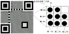
Fig. 3 illustrates a pattern in which the second code is expressed with dots smaller than the sub-lattice. Hereinafter, the square in which the second code is set is referred to as a specific square. In the example of fig. 3, the center of the 16 sub-tiles is configured with dots smaller than the sub-tile area. That is, in the example of fig. 3, the center of 16 sub-squares is the imaginary point. Information is expressed according to whether or not a point is placed on a virtual point. A dot is one of the labels. Although the dots are arranged at the center of the sub-scale in fig. 3, the positions of the dots are not limited to the center of the sub-scale. Therefore, it can be said that fig. 3 arbitrarily sets one or more virtual points at the position of the specific cell having the coordinate information. In fig. 3, since information is expressed according to whether or not a point is placed on a virtual point, it can be said that numerical data is defined based on a virtual point placement flag.
For example, assuming a square grid size of 0.250mm by 0.250mm, a 16-equally divided sub-grid would have a size of 0.0625mm by 0.0625 mm. On the other hand, a printer having a resolution of 600dpi has a minimum printable size of 25.4mm/600 of 0.042mm and a dot size of 0.042mm × 0.042mm, and it is generally experienced that the minimum printable size is less than 0.050mm × 0.050mm, taking into account contour displacement due to ink blurring or the like during printing. Of course, if the printing accuracy is high, it is undoubtedly closer to 0.042mm × 0.042 mm. On the other hand, if printing is performed using a printer having a higher resolution, for example, a resolution of 1200dpi, finer printing can be realized.
In the example of fig. 3, the square grid has an area of 0.250 × 0.250 to 0.0625 square mm, and the maximum area at 8 points is 0.0249 × 0.0249 × 3.14 × 8 to 0.0156 square mm. In this case, if dots are printed using a general high-precision printer, even if the quality is not good, the area of dots in the square is only 24.96%, which is approximately close to 25% described in patent document 1. Therefore, the dot pattern of FIG. 3 may have,16C8+16C7+16C6+16C5+16C4+16C3+16C2+16C1+16C039,203 patterns can be selected. The dot pattern of fig. 3 can be said to be a mark that does not hinder reading of the first code.
In contrast to the sub-squares in fig. 2, the dots in fig. 3 are characterized by the presence of bright areas between the dots. That is, as shown in the comparative example, in the case of the sub-cell of fig. 2, the same color is set in two adjacent sub-cells, or in a sub-cell and an adjacent cell, and as a result, the regions of the same color are continuous or integrated. This may make it difficult to distinguish between a single sub-tile and a set of multiple sub-tiles at the extreme read resolution. On the other hand, in the structure of fig. 3, dark dots are clearly divided in the light color region, and the dark dots can be easily recognized even at the limit of the reading resolution. The dot pattern of fig. 3 can be said to be one of the patterns of the configuration in which the contact between the marks is avoided. Further, the dot pattern of fig. 3 can be said to avoid an arrangement in which the mark is in contact with the boundary between a specific cell and its adjacent cell. Further, although black is used as a dark color and white is used as a light color in the example, the colors used for the code, the pattern, or the mark are not limited to black and white in the present embodiment. For example, dark squares are not limited to black squares and light squares are not limited to white squares.
Fig. 4 shows another example of the second code. Fig. 4 is an example of three rows and three columns in total of arrangement points at the center of each area into which squares are nine equally divided. That is, in the example of fig. 4, the centers of the nine sub-squares are also imaginary points. Information is expressed according to whether or not a point is placed on the virtual point.
In the same manner as in fig. 3, when the size of the square is 0.25mm × 0.25mm and the diameter of the dot is 0.05mm, the distance between the dot and the boundary line between the dots is 0.25/3 to 0.05mm, which is 0.03mm, and the dots are more easily recognized as the distance between the dots is longer than in fig. 3. Also in the case of fig. 4, when 8 dots are arranged at the maximum, the ratio of the area of the dots to the area of the cell is 25.12%, which is a value approximately close to the condition of patent document 1. The amount of information that can be represented by the dots in FIG. 4 is9C8+9C7+9C6+9C5+9C4+9C3+9C2+9C1+9C0Approximately 9 bits in 511 kinds. The dot pattern of fig. 4 can be said to be one of the patterns of the configuration in which the contact between the marks is avoided. Further, the dot pattern of fig. 4 can be said to avoid an arrangement in which the mark is in contact with the boundary between a specific cell and its adjacent cell. Therefore, the dot pattern of fig. 4 can also be said to be a mark that does not hinder reading of the first code.
Fig. 5 is a modification of fig. 4, in which dots are arranged in three columns, three dots are arranged in the first column, two dots are arranged in the second column, and three dots are arranged in the third column. The arrangement positions of the dots of the second column in the row direction are between the first row and the second row, and between the second row and the third row. That is, also in the example of fig. 5, the center of the three squares in the first column, the center of the three squares in the third column, and the intersection of the boundary line L1 of the first row and the second row of the second column and a vertical line (indicated by a dotted line) passing through the center of the square orthogonal thereto, and the intersection of the boundary line L2 of the second row and the third row of the second column and the vertical line are each a virtual point. Information is expressed according to whether or not a point is placed on the virtual point.
Therefore, in fig. 5, the distance between the dots is further longer than in fig. 4, and the dots are more easily recognized. Also in the case of fig. 5, when 8 dots are arranged at the maximum, the ratio of the area of the dots to the area of the cell is 25.1%, which is approximately close to the value of patent document 1. In addition, the amount of information that can be represented by the dots in fig. 5 is8C8+8C7+8C6+8C5+8C4+8C3+8C2+8C1+8C0256, which are 8 bits. The dot pattern of fig. 5 can be said to be one of the patterns of the configuration in which the contact between the marks is avoided. In addition, the dot pattern of fig. 5 can be said to avoid an arrangement in which the mark is in contact with the boundary line between a specific cell and its adjacent cell. Therefore, the dot pattern of fig. 5 can also be said to be a mark that does not hinder reading of the first code.
Fig. 6 shows another example of the second code. In the example of fig. 6, imaginary points (X1, Y1) are set in one square. The virtual points (X1, Y1) may be, for example, coordinate values designated with the lower left point of the square grid as the origin (0, 0). However, this does not represent that a mark showing a virtual point is arranged at a position of the virtual point. At the same time, a mark showing a reference point may be arranged at the position of the virtual point. The information may be defined by arranging points at intervals of a predetermined angle θ, for example, 45 degrees, on a virtual circumference having a radius d and centered on the virtual point. In this case, if the distance d is fixed and the number of points is limited to one, 3 bits of information can be defined around one imaginary point. The amount of information that can be expressed when a maximum of 8 points is used is the same as in the case of fig. 5. Therefore, it can be said that in fig. 6, data is defined based on the virtual point arrangement marks. The dot pattern of fig. 6 can be said to be a pattern of an arrangement in which contact between marks is avoided. In addition, the dot pattern of fig. 6 can be said to avoid an arrangement in which the mark is in contact with the boundary line between a specific cell and its adjacent cell. In fig. 6, virtual points may be arbitrarily set in the squares. Therefore, it can be said that 1 or more virtual points are arbitrarily set at positions having coordinate information in a specific cell. The dot pattern in fig. 6 can be said to define numerical data based on at least one of the direction and distance in which the marks are arranged with the virtual dots as the starting points.
As described above, in the present embodiment, dots surrounded by light color around dark color are used, as compared with the comparative example in the two-dimensional code such as the one-dimensional barcode or the QR code in which the squares or the subdivided sub-squares constituting the code are entirely colored in dark color. By arranging such dots in a square grid such as a light color, a second code of higher density than the code of the comparative example can be defined in the square grid.
Although the reading resolution of the reading device varies, in general, if the area of the dots occupies about 50% of the area of the specific cell, it is impossible to determine which of two or more colors (white cells and black cells if white and black such as QR codes are used) is recognizable, and it is preferable to avoid the determination as much as possible. Usually, the square can be judged to be a specific square under 33% (one third). It is particularly preferable that the content of the compound is 25% or less.
In addition, although fig. 3 to 6 illustrate composite codes in which dark dots surrounded by light dots are arranged, it is also possible to arrange light dots in dark squares. In this case, the bright dots are clearly distinguished by the dark regions, and even at the limit reading resolution, the bright dots can be easily recognized.
< location of second code within first code >
The following will explain the arrangement position of the second code within the first code with the QR code as the first code, with reference to fig. 7 to 13. The arrangement position of the second code in the first code herein refers to a position of a cell (referred to as a specific cell as described above) that defines the second code when the first code expresses information by a combination of dark cells and light cells like a QR code. Here, the QR code is taken as an example of the first code, but the first code is not limited to the QR code.
In the QR code of the present embodiment, the upper left is the origin, the horizontal right is the x direction, the vertical downward direction is the y direction, and the position information (x, y) is expressed by x being 0, 1, 2 to m, and y being 0, 1, 2 to n, using natural numbers m, n. On the other hand, the data of the QR code (first code) configures data from the lower right corner. In the present embodiment, data is arranged from right to left with reference to two squares in the X direction.
Fig. 7 shows an example in which the second code is arranged only on the light cell (white cell in the figure) of the data and error correction code arrangement region. In fig. 7, the light squares forming the second code are given consecutive numbers from 1 to 178. The serial number is a symbol for identifying the second code formed by the dots arranged in each cell in the description of the present embodiment, and is not a pattern (graphic shape) actually formed on the cell.
However, the serial number can be said to be unique identification information given to the square having the second code, and thus can also be understood as a number used for information processing on, for example, a generating device that generates a composite code or a reading device that reads a composite code. The second code of dot composition exemplified in fig. 3 to 6 is formed on each of the numbered squares. Hereinafter, the shape within the cell representing the second code composed of dots is referred to as a dot pattern. In each of fig. 7 to 13, the number given to each cell can be said to be a number for identifying a dot pattern in the cell.
In fig. 7, the second codes are arranged in the same order as the arrangement order of the first codes. That is, in the QR code squares, two squares juxtaposed in the X direction are scanned in the order of the first right square and the second left square from the lower right corner, and a second code composed of dark dots is set in the light square. Examples of the second code are such as fig. 3 to 6. However, the second code is not limited to the examples of fig. 3 to 6.
As described above, the number given to each cell in fig. 7 does not specify the type of dot pattern, but can be understood as information for identifying a cell having a dot pattern. Of the plain squares in fig. 7, the square to which the second code is assigned can be said to be one of the squares referred to as a specific square. The identification information given to the bright squares in fig. 7 is referred to as a specific square index. The specific grid index is identification information corresponding to the coordinate values of each grid in one-to-one correspondence in the scanning order. It can also be said that a plurality of specific squares are formed, which define numerical data sorted according to specific square indexes. Further, it can be said that the column of the second code is constituted by a plurality of specific squares that can be mutually identified by specific square indexes.
Further, when generating a composite code, if the generating apparatus of the composite code scans the squares and sets the second code composed of the dot pattern in the same order as the squares of the first code, for example, the QR code, the reading apparatus of the composite code may scan the squares and decode the second code composed of the dot pattern in the same order as the composite code generating apparatus. Therefore, the composite code generated by scanning in the same order as the squares of the first code, for example, the QR code, does not need to acquire information from the generating device, and can be read separately using the reading device. This is because the reading device may correspond the specific grid indexes to the coordinates in one-to-one correspondence in the same scanning order as the generating device.
On the other hand, when generating a composite code, if the generating device of the composite code scans the squares in a different order from the order in which the squares of the first code, for example, the QR code are scanned and sets the second code composed of the dot pattern, the reading device of the composite code needs information capable of associating the specific square index with the coordinate value in one-to-one correspondence in order to decode information from the composite code. In the following embodiments, a processing example in which the composite code reading apparatus decodes information from the composite code without information that one-to-one corresponds the specific square index and the coordinate value, and a processing example in which the reading apparatus decodes information from the composite code with information that one-to-one corresponds the specific square index and the coordinate value are exemplified.
Further, the information that makes the specific grid index correspond to the coordinate values one-to-one exemplifies the following two cases: the specific grid index directly corresponds to the coordinate value; the specific grid index indirectly corresponds to the coordinate value. In the case of indirect correspondence, a reference index is assigned to the coordinates of all the squares, and the specific square index corresponds to the reference index.
There are ways to read the composite code by reading the first code and the second code simultaneously, and ways to read the first code and the second code in two stages. In the method of reading the first code and the second code simultaneously, after the shading of the cell forming the first code is determined, before the shading of the next cell is determined, whether or not the dot pattern constituting the second code exists in the cell whose shading has been determined is determined. Then, for the square where the dot pattern exists, decoding of the numerical value of the dot pattern will be performed. The numerical values are integrated in units of a set in which a predetermined number of squares are combined, and the second code is decoded.
Fig. 8 shows an example of the arrangement of the composite code in which the second code is also arranged on the white square around the positioning mark. In fig. 8, as in fig. 7, the rows of squares (squares arranged in the vertical direction with respect to the paper) are grouped into one group for each two rows. When the first two columns are scanned from bottom to top, the right square grid is preferentially scanned from the left square grid and the right square grid, and the bright square grids are numbered continuously. For example, in the right two columns, the left side of the lowermost row has a light color cell, and is given a consecutive number of 1. While the second row from the bottom has no consecutive numbering because there are only dark squares. Next, for example, in the eighth line from the bottom, since both the left and right squares are bright, serial numbers 6 and 7 are given in order with priority to the right square. The same applies below. In addition, the squares are scanned from top to bottom in the third and fourth columns from the right, and in the two columns, the right square is still scanned preferentially, and the light squares are numbered consecutively.
Fig. 9 shows a case where the second code is arranged in each of the light squares including the positioning marks and the correction marks shown in fig. 1. Therefore, the second code is arranged in the same manner as in the cells in which data is arranged in fig. 7 and 8, in the bright color cells around the positioning mark, the bright color cells in the timing mark, and the bright color cells in the format information described in fig. 1.
Fig. 10 shows an example of a composite code in which the second code is arranged not only on the light squares but also on the dark squares. In this case, the second code may be arranged not only in the data and error correction code area but also in a square other than the positioning mark and the correction mark. In addition, the second code may be arranged on all the squares (light squares and dark squares) including the positioning marks and the correction marks. Here, when the second code is arranged on the dark cell, the color becomes light. Fig. 10 shows an example in which bright dots are arranged on dark cells of the specific cell index 27, in the same configuration as that shown in fig. 5.
Fig. 11 shows an example of the arrangement of a composite code in which dot patterns of each cell constituting the second code appear cyclically in a predetermined number of cells. In fig. 11, the consecutive numbering of the squares from 1 to 16, that is, the specific square index, is arranged cyclically. In fig. 11, dot patterns corresponding to specific cell indexes 1 to 16 are arranged from right to left with reference to two cells in the X direction from the lower right corner. By thus circularly arranging a prescribed number of second codes (dot patterns), the reading device can read the second codes from a part of the first codes (for example, a prescribed number of squares of the QR code). As shown in fig. 11, a part of a group of second codes composed of a predetermined number of specific square indexes (nos. 1 to 16) is called a sub-code.
In the case of the composite code of fig. 11, a table in which numbers (for example, numbers 1 to 16) indicating the types of second codes in the squares and position coordinates of the squares (or consecutive numbers of the squares) are associated with each other may be generated on the generating device side and transmitted to the reading device. However, the arrangement rule of the second code may be predetermined, and the reading device may generate the serial number (specific cell index) on the cell in which the second code is set according to the same rule as the generation device. The reading device of the composite code may arrange and integrate the values read from the second code in the order of consecutive numbers according to the above-mentioned rules.
As shown in fig. 11, when a predetermined number of consecutive numbers (specific cell indexes) of the loop are set in each cell, the second code in each cell may be integrated into the loop of the consecutive numbers (specific cell indexes) and confirmed. For example, among N (for example, 16) squares to which specific square index of 1 to 16 is given, a dot pattern indicating the head of the second code may be given to the head square, and a dot pattern indicating the end of the second code may be given to the end square.
Fig. 12 shows an example of arrangement in which a predetermined number of dot patterns constituting the second code are cyclically arranged on all the light squares in the QR code, which is one type of the first code. That is, although the rule of giving consecutive numbers (specific cell indexes) shown in fig. 11 is adopted in fig. 12, the second code is arranged on all the light cells. Therefore, in fig. 12, as in fig. 9, the second code can be arranged on all the bright squares in the QR code, that is, on the bright squares of the positioning marks, the correction marks, and the like.
In this case, it is not necessary to simultaneously execute the reading process of the QR code and the reading process of the second code. For example, the second code may be read after the reading of the first code is completed. In this case, when the second code of the composite code is generated and read, the squares are scanned downward from the origin at the upper left corner, and indexes of 1 to 16 are given to the light squares detected during the scanning. In the embodiment of fig. 12, the following processing sequence is cyclically executed: the grid moves from the minimum value to the maximum value of the X coordinate while the Y coordinate moves from the maximum value to the minimum value and then from the minimum value to the maximum value.
In fig. 12, specific square indexes are assigned in order from the minimum value (1) to the maximum value (16), and then the maximum value (16) to the minimum value (1) are assigned in order. In this case, the composite code generation device sets a dot pattern corresponding to the specific cell index on each cell, and generates a composite code. On the other hand, the reading device of the composite code may search for the specific squares in the same order as the generating device, set the specific square index in the same rule as the generating device, determine the order of the squares in the composite code, and decode the second code.
When the second codes are arranged on all the white squares in the QR code, the generating apparatus may arrange the second codes in the same arrangement order (the scanning order of the QR code) as the first codes, as described with reference to fig. 7 to 10. And the reading device may simultaneously perform the reading process of the QR code and the reading process of the second code.
Fig. 13 is an example of a composite code in which dots are arranged in a margin portion around a QR code. In addition to all white squares in the QR code, a mute region (a blank portion around the QR code) may be provided with the second code. In the example of fig. 13, the generating device and the reading device search for the specific cell as the cell moves, and when the specific cell is searched and the specific cell set with the second code is found, the specific cell indexes are numbered in order from the minimum value (1) to the maximum value (16).
< arrangement of dot pattern in cell >
The arrangement of the dot pattern in the squares forming the second code will be explained below based on fig. 14 to 23. Fig. 14 shows an example of the arrangement of the dot pattern of the definition data according to the distance and direction from the virtual dot. The dot pattern of the data defined according to the distance and direction from the imaginary point is the dot pattern illustrated in fig. 6.
The second code defines information based on at least one of a distance d from a virtual point to a point and a direction of a straight line from the virtual point to the point by setting the virtual point in the cell. The position of the virtual point is set with the origin of the square as a reference. The origin of the squares may be exemplified by the bottom left point of the squares, but is not meant to be limited by the definition of the origin of the squares. Fig. 14 illustrates a case where the distance d is a fixed value. However, the distance d may take a plurality of values to define the information. In fig. 14, dots are arranged in 45 degrees around a virtual point (distance d), and numerical value data 000 to 111 are defined.
Further, the direction of the squares is decided based on a reference shape portion of the first code, for example, a positioning mark of the QR code (see fig. 1). Therefore, the arrangement direction of the points in the grid with respect to the virtual points in the grid is set based on the coordinate axis determined by the positioning mark. For example, in each square in fig. 14, when a reference is given with an axis pointing rightward from an imaginary point as a direction, the numerical value 000 corresponds to a direction of 90 degrees. Further, the numerical values 001 to 111 correspond to directions rotated clockwise by 45 degrees from the direction of the numerical value 000 (for example, from the direction of 90 degrees), respectively.
Therefore, the generating device for generating the composite code can set virtual points in the square, form points at positions determined by the distance and direction corresponding to the numerical data, and print the points by a printer or output the points on a screen by an electronic medium, a broadcast medium, a storage medium, or a communication medium. On the other hand, the reading device that reads the composite code may set the imaginary point and the direction within the cell based on the reference shape portion in the first code, recognize the distance and the direction from the imaginary point to the point detected within the cell, and decode the numerical value from the dot pattern.
Fig. 15 is an example of defining information according to whether points are arranged on imaginary points. The dot pattern of the information defined according to whether or not the dots are arranged on the virtual dots is, for example, the dot pattern exemplified in fig. 3 to 5.
Therefore, the generating device that generates the composite code can set virtual points in the square, form dots on the virtual points corresponding to the numerical data, or form an image without dots, and print it by a printer, or output it on a screen by an electronic medium, a broadcast medium, a storage medium, or a communication medium. On the other hand, a reading device that reads the composite code may set imaginary points within a cell based on the reference shape portion in the first code, recognize whether there is a point on each imaginary point, and decode a numerical value from the dot pattern. Further, the composite code may be stored in a storage medium and decoded by a program. That is, the composite code can be generated and decoded in the virtual space.
Fig. 16 is an example of setting a virtual point on the second code illustrated in fig. 4. In fig. 16, a virtual point (X) is set at the center of each region obtained by dividing one square 3 by 3 and dividing by 9i,Yj). As shown in fig. 4, when dark dots are arranged on a light cell, by arranging dots on at most 8 of 9 virtual points, the entire cell can be recognized as a light cell, and dark dots can be arranged on virtual points.
Fig. 17 shows an example of setting virtual points on the second code shown in fig. 5. In fig. 17, among the three rows and three columns of imaginary points in fig. 16, the line positions of two imaginary points in the middle column are arranged at the middle positions of the lines of three imaginary points in the first column and three imaginary points in the third column.
Fig. 18 shows a modification of the virtual point positions. The position of the virtual point is not limited to the case of fig. 16 and 17, and various virtual points may be used. For example, the number of virtual points may be one or two or more in the square. For example, the position of the virtual point may be set at the center of the square and at positions on diagonal lines from the center of the square to the four corners of the square. When two virtual points are provided in the square, the virtual points may be provided at positions close to two corners forming a diagonal line passing through the center. When three imaginary points are arranged in the square grid, one of the imaginary points can be arranged between two opposite sides of the square grid, and the line connecting the middle point of one of the sides to the center of the square grid is close to the position of the side; the remaining two virtual points are disposed at positions close to both ends of the opposite sides of the side (two corners formed by the opposite sides and the sides orthogonal to the opposite sides).
Fig. 19 is an example of information indicating that dot patterns are not set in cells. For example, when a plurality of virtual points are provided in a cell, the placement of the points on the virtual points at the center of the cell may represent undefined information.
Fig. 20 is an example in which a line segment, one end of which is located on an imaginary point, constitutes the second code. That is, not only points may be arranged around the virtual point and information may be defined by the distance and direction as shown in fig. 14, but also line segments may be arranged around the virtual point and information may be defined by the length and direction of the line segments as shown in fig. 20. A line segment is one of the labels. The line segment pattern of fig. 20 can be said to be one of the patterns of the configuration in which the contact between the marks is avoided. Further, the line segment pattern of fig. 20 can be said to avoid an arrangement in which the mark is in contact with the boundary line of a specific cell and its adjacent cell. Also in fig. 20, a part of the numerical data may be defined by at least one of the direction and the length of the line segment.
Fig. 21 is an example in which a line segment, the center of which is located on an imaginary point, constitutes the second code. In fig. 21, a part of the numerical data may be defined by at least one of the direction and the length of the line segment. In fig. 22, the length of the line segment changes in multiple stages, and the length of the line segment is one element of the definition information. When a line segment is arranged as the second code, the position of the imaginary point is not limited to the center of the line segment. For example, fig. 23 shows an example in which a line segment constitutes the second code, and is located at a position on the virtual point (for example, a position from one end of the line segment to 1/3) where the line segment is divided into a predetermined ratio, not at the center of the line segment. Therefore, in fig. 22 or 23, a part of the numerical data may be defined by at least one of the direction and the length of the line segment. In fig. 20 to 23, it can be said that some of the numerical data are defined by arranging arbitrary positions of line segments on imaginary points.
As described above, in fig. 14 to 23, it can be said that one or more virtual points are arbitrarily set at the position of the specific cell having the coordinate information. In fig. 14 to 23, it can be said that numerical value data is defined by arranging marks based on imaginary points. Further, although the marks are defined by the light areas and the dark areas in fig. 14 to 23, the marks may be defined by any two of R (red), G (green), and B (blue), for example. Therefore, it can be said that one of composite codes defining a part of numerical value data by at least one of a mark arrangement method based on the shape, color, imaginary point, and whether or not a mark is arranged is shown in fig. 14 to 23. Further, in fig. 14 to 23, the second code is defined by a point or a line segment. The shape of the marker may be any polygon or near-circle.
< example of actual configuration points in QR code >
Fig. 24 is a diagram of a structural example (1) of a composite code in which a dot pattern is arranged in a cell of a QR code, which is one type of a first code. A dot pattern defining information according to a distance and a direction from an imaginary point is shown in the configuration example (1) as an example of the second code. The dot pattern defining information according to the distance and direction from the imaginary point is as shown in fig. 14. In fig. 24, a dark area filled with a shadow and a light area without a shadow are formed on a portion of the QR code. Near the center within the bright area, a phantom point is shown marked with a plus sign ("+"). It should be noted that the marks such as plus ("+") are for illustrating the position of the imaginary point on the figure, and the marks such as plus ("+") are not drawn on the actual composite code. Each light color region is illustrated as a dot substantially at 45 degrees around the virtual point.
Fig. 25 is a diagram of a structural example (2) of a composite code in which a dot pattern is arranged in a cell of a QR code, which is one type of first code. In the configuration example (2), as an example of the second code, a plurality of virtual points are provided in the bright color region, and information is defined according to whether or not a point exists on the virtual points, and in fig. 25, four virtual points are provided in one bright color region, but the number of virtual points is not limited to four in this embodiment.
Fig. 26 is a diagram of a structural example (3) of a composite code in which dot patterns are arranged in a cell of a QR code, which is one type of first code. In the configuration example (3), as an example of the second code, a plurality of virtual points are set in a bright color region, and information is defined according to whether or not a point exists on the virtual points. In fig. 25, one dot is arranged in each of the bright regions, but in fig. 26, 0 to 3 dots are arranged in one of the bright regions.
Fig. 27 is a diagram of a structural example (4) of a composite code in which a dot pattern is arranged in a cell of a QR code, which is one type of first code. Configuration example (4) as an example of the second code, the number of imaginary points and the arrangement method of the points are different depending on the specific squares defining the dot pattern. That is, the number of virtual points, the arrangement position of the virtual points, and the arrangement method of the points with respect to the virtual points may be different depending on the position of the specific cell. A dot pattern arrangement method of information defined by a distance and a direction from a virtual point as shown in fig. 24, for example, is shown; as shown in fig. 25 and 26, the arrangement of the dot pattern of the information is defined according to whether or not there is a dot on the virtual dot. In addition, the number of dots in one bright region may be one or more.
In any case, the method of defining the second code for different positions of the squares may be common to the generation apparatus of the composite code and the reading apparatus that acquires information from the composite code. Alternatively, for example, information specifying the definition method of the second code may be added to the format information center shown in fig. 1.
Fig. 28 is a diagram of an example of a structure (5) of a composite code in which dot patterns are arranged in a cell of a QR code as a first code. In the configuration example (5), as an example of the second code, information is defined by arranging a bright color point in a dark-colored region. Fig. 28 illustrates a dot pattern which exchanges the dark colors and the light colors of the dot pattern illustrated in fig. 26 in which dark color dots are arranged in the light color region.
Fig. 29 is a diagram of a structural example (6) of a composite code in which a dot pattern is arranged in a cell of a QR code, which is one type of the second code. Of the configuration examples (6), as an example of the second code, it defines information by arranging line segments in a bright color region. The configuration example (6) is the same as fig. 20, and a line segment having one end located on an imaginary point is arranged.
Fig. 30 is a diagram of an example (7) of a structure of a composite code in which line segment patterns are arranged in a cell of a QR code, which is one type of the second code. In the configuration example (7), the line segments are arranged by different arrangement methods depending on the specific squares in which the second code is arranged. For example, a line segment in which one segment of the line segment is a virtual point, a line segment in which the center of the line segment is a virtual point, a line segment in which the length of the line segment changes in multiple stages and which has one of the elements of the definition information, a line segment in which the position of the line segment is a virtual point in a predetermined ratio, and the like can be used.
Fig. 31 is a diagram of an example (8) of a structure of a composite code in which line segment patterns are arranged in a cell of a QR code as an example of a second code. Configuration example (8) as an example of the second code, each of specific squares in which the second code is arranged by selecting one of a line segment pattern and a dot pattern, respectively. In addition, a line pattern arrangement method and a dot pattern arrangement method are defined for each specific cell. The method of arranging these second codes may be common to the generation device that generates the composite code and the reading device that reads the composite code.
In addition, although not shown in fig. 24 to 31, the second code (fig. 24 and the like) defined in the light area and the second code (fig. 28) defined in the dark area may also be combined to form a composite code.
< composition of System >
Fig. 32 is a diagram of a composition example of an information system that provides a service by composite codes. The information system connects a management server MS1, content servers CS1, CS2, and a user device UD1 via a network N1. Meanwhile, the information system may also have a user device UD2 which is not connected to the network N1.
The management server MS1 has a composite code generation means CGM and a composite code analysis means CAM composite code generation means CGM converting input digital data into a composite code. The management server MS1 can accept digital data from the content server CS1 through the network N1, for example, and generate image data of a composite code by composite code generation means CGM, and then feed back to the content server CS 1.
The composite code analysis means CAM analyzes the input composite code and converts the composite code into original digital data. The management server MS1 may, for example, accept the image of the compound code from the user device UD1 via the network N1, and generate the original digital data by the compound code parsing means CAM, and then feed back to the content server CS 1.
The content server CS1 has a communication means CMS1 and a composite code output means COUT 1. The content server CS1 provides various content or services to user devices UD1, UD 2. The contents provided by the contents server CS1 are provided to the user equipment through a broadcasting system such as a broadcasting medium, a communication medium, etc., or an electronic information communication system. The content may be exemplified by content including an image (a still image or a moving image). Broadcast media refer to media that deliver content by electromagnetic waves, such as television broadcasts. The communication medium refers to a medium for transmitting contents via a wired or wireless network, such as the internet.
The content server CS1 may also provide content to user devices UD1, UD2, etc. via storage media such as CD, DVD, blu-ray disc, USB memory, etc. Further, the content server CS1 may also provide content to user devices UD1, UD2, and the like via print media. The printing medium includes paper, a surface of an object, and the like, which can form an image by ink.
The content server CS1 transmits the digital data relating to the provided content to the management server MS1 via the network N1, converting it into a compound code. Then, the content server CS1 acquires the composite data converted by the management server MS1 through the network N1 and provides it together with the content to the user devices UD1, UD2, and the like through the network N1. The digital data related to the content includes various text information related to the provided content, a URL related to the provided content, identification information related to the provided content, authentication information for access, or the like.
The content server CS2 has a composite code generation means CG2 in addition to the communication means CMS2 and the composite code output means COUT 2. Accordingly, the content server CS2 can convert digital data related to the provided content into a composite code through the composite code generating means CG 2. Therefore, the content server CS2 does not need to transmit the digital data to the management server MS1 and convert it into a composite code. The functions of the communication device CMS2 and the composite code output means COUT2 are the same as those of the communication means CMS1 and the composite code output means COUT1 of the content server CS 1. The content servers CS1 and CS2 include, for example, an information processing device used in cooperation with a broadcasting device of a broadcasting station, a server providing content on the internet, a printing device at a printing company or the like, a server used in cooperation with a printer, a computer built in the printing device, and the like.
The user device UD1 has communication means CMU1 and image input means IIN 1. The image input means IIN1 has image input means capable of inputting images from the following ways: a television screen as a broadcast medium, a screen including a graphic object on web contents as a communication medium, a screen including a graphic object output from a storage medium, or a printed matter formed on a print medium. The image input means is a scanner or a camera having an image pickup element such as a Charge-coupled Device (ccd), a Metal-oxide-semiconductor (MOS) image sensor, a Complementary Metal-oxide-semiconductor (CMOS) image sensor, or the like.
The user device UD1 transmits the input image itself, or the composite code portion in the input image, to the management server MS1 via the network N1, and decodes the digital data encoded as the composite code. Then, the user device UD1 performs processing corresponding to the digital data based on the obtained digital data and the content provided from the content servers CS1, CS2, and the like. The processing corresponding to the digital data includes, for example: a validity determination based on the digital data, a determination of whether the content can be accessed, a conversion of a method of providing the content to a user, and providing other content related to the content, and the like.
The user device UD2 includes image input means IIN2 and composite code analysis means CA 2. The user device UD2 decodes the digital data encoded as a composite code from the input image using composite code parsing means CA 2. Therefore, the user device UD2 does not need to transmit the input image and the composite code portion in the input image to the management server MS1 to decode the digital data. Then, the user device UD2 performs processing corresponding to the digital data based on the obtained digital data and the content provided from the content servers CS1, CS2, and the like. Examples of user devices UD1 and UD2 include personal computers, tablet computers, smart phones, and the like.
Fig. 33 is an exemplary diagram of the hardware composition of the information processing apparatus 10. The information processing device 10 is applicable to the management server MS1, the content servers CS1, CS2, and the user devices UD1 and UD2 of the present embodiment. The information processing apparatus 10 has a CPU11, a main storage 12, and an external device, and executes information processing by a program. The CPU11 is also referred to as a processor. The external devices include, for example, an external storage device 13, a display device 14, an operation section 15, a communication interface 16, an image input interface 17, and an image output interface 18.
The CPU11 executes an executable computer program disposed in the main storage device 12 and provides the functions of the information processing device 10. The main storage device 12 stores computer programs executed by the CPU11, data processed by the CPU11, and the like. The main storage device 12 includes a Dynamic Random Access Memory (DRAM), a Static Random Access Memory (SRAM), a Read Only Memory (ROM), and the like. Further, the external storage device 13 may be used as, for example, an auxiliary storage area of the main storage device 12, and store computer programs executed by the CPU11, data processed by the CPU11, and the like. The external storage device 13 is a mechanical hard Disk, a Solid State Disk (SSD), or the like. Further, a drive device of a removable storage medium may also be provided on the information processing device 10. Examples of removable storage media are blu-ray disc, DVD, CD, flash memory cards, etc.
The display device 14 includes a liquid crystal display, a cold light sheet, and the like. The operation section 15 includes a keyboard, a pointing device, and the like. In the present embodiment, the pointing device is exemplified by a mouse. The communication interface 16 exchanges data with other devices on the network N1. For example, the CPU11 communicates with other devices on the network N1 through the communication interface 16. In addition, the communication interface 16 may also be connected to a broadcasting device. The broadcasting device may, for example, convert digital data from a baseband signal into a high frequency signal, and transmit the converted high frequency signal through a broadcasting band via a high frequency amplifier and an antenna.
The image input interface 17 is connected to a camera, a scanner, and the like, and acquires image data from various media. Examples of the various media include a screen of a television image receiver, a display of a computer, printed matter such as books, a visually recognizable pattern formed on a surface of an object, and the like.
The image output interface 18 is connected to a printing device, a printer, and the like, and outputs image data to a print medium. Further, although not shown in fig. 33, the information processing apparatus 10 may be connected with a camera, a scanner, or the like via the image input interface 17. The information processing apparatus 10 can also be connected to a printing apparatus, a printer, and the like via the image input interface 18.
Further, when the information processing apparatus 10 is applied to the management server MS1, the image input interface 17 and the image output interface 18 may be absent. When the information processing apparatus 10 is applied to the content servers CS1, CS2, the image input interface 17 may be absent. Further, when the information processing apparatus 10 is applied to a user apparatus, the image output interface 18 may not be present.
< treatment Process >
The following describes the processing flow of the present information system according to fig. 34 to 36. Hereinafter, the content servers CS1 and CS2 are collectively referred to as a content server CS. That is, the following processing may be performed by any one of the content servers CS1 and CS 2. Meanwhile, user devices UD1 and UD2 are collectively referred to as user devices UD. That is, the following processing may be performed by any one of user devices UD1 and UD 2.
Fig. 34 is a flowchart illustrating the composite code generation processing a by the content server CS. This is called composite code generation processing a for distinguishing it from composite code generation processing B of fig. 38. It can be said that the content server CS executes the processing as the composite code generation device by the processing of fig. 34 and 38. In the process of fig. 34, the content server CS generates shape information of the first code (S11). For example, when the first code is a QR code, the content server CS decides the arrangement of the light and dark squares in the QR code.
Next, the content server CS inputs digital data to be converted into a second code (S12). The digital data is, for example, information related to content provided by the content server CS. The digital data is input from, for example, a storage device associated with the content provided by the content server CS.
Next, the content server CS performs binary code processing on the digital data (S13). I.e. the content server CS converts the digital data into a binary one-dimensional bit sequence. Then, the content server CS divides the binary code processed data into data of each square of the first code (S14). That is, the content server CS divides the binary code data by the maximum number of bits that can be represented by the dot pattern in each square. Then, the content server CS allocates the divided data to a square where the second code can be arranged, according to a predetermined rule.
For example, when the first code is defined by a combination of light and dark squares, and the second code is defined by dark dots, the squares in which the second code can be arranged are the light squares. For example, when the first code is defined by a combination of a light square and a dark square and the second code is defined by light dots, the square in which the second code can be arranged is a dark square. The content server CS determines the squares where the second codes are arranged, and the arrangement order according to a prescribed rule such as fig. 7, fig. 8 to fig. 13, and the like. Further, as already shown in fig. 11, the content server CS may repeatedly form a plurality of specific squares forming the second code, and arrange the squares.
After that, the content server CS generates shape information of the second code (S15). That is, in the processing at S14, the content server CS converts the binary code data divided into the respective squares into coded image data with reference to virtual points within the squares. The coded image data based on the virtual points in the squares is, for example, an image shown in fig. 3 to 6. Then, the content server CS outputs the image data (S16). The output destination is a print medium generated such as a printer, a display device transmitted to the user device UD through electronic information via the network N1, a playback through a broadcast medium, or the like. It can be said that the content server CS that executes the processing of S11 and the processing of S16 has one of the first generation means that generates the first code. It can be said that the content server CS that performs the processing of S12 to S16 has one of the second generation means. Therefore, it can be said that when the content server CS is configured with a plurality of marks in a specific cell as the second generation means, the configuration in which the marks are in contact with each other can be avoided. It can be said that the content server CS excludes, as the second generation means, the second code and the arrangement in which the specific cell is in contact with the boundary line between the adjacent cells of the specific cell.
When the content server CS is the content server CS1, the digital data is transmitted to the management server MS1, and the processes of S13 to S15 are performed by the management server MS 1. The content server CS1 may output the image data generated by the management server MS1 to a printer, a user device UD on a network, a broadcast medium, or the like.
Fig. 35 is a flowchart illustrating the composite code reading process a by the user device UD. This is called composite code reading processing a for distinguishing it from composite code reading processing B of fig. 39. It can be said that the user device executes the processing as the composite code reading device by the processing of fig. 35, 39. In the process of fig. 35, the user device UD inputs an image of a composite code input from a scanner, a camera, or the like via the image input interface 17, and recognizes the format and the checkered configuration of the first code (S20). For example, the user device UD recognizes the direction of the QR code by locating the logo, and corrects the image distortion by correcting the logo. And the user device UD also identifies the configuration interval of the grids according to the timing identifier, and identifies the data of the QR code and the configuration position of the error correcting code. Thereafter, the user device UD processes each square of the composite code in the order of the arrangement of the first code. For example, the user device UD processes two columns of squares on the right side in the upward direction from the square on the lower right corner of the QR code, and processes the squares on the third column and the fourth column in the upward and downward direction after the processing of the two columns of squares is completed. Thereafter, the data squares and the squares of the error correction code are also processed in units of two columns. The processing of each square will be described below.
The user device UD acquires an image of the next cell, analyzes the first code, and judges the shading (S21). Next, the user device UD determines whether or not the second code is defined in the pane being processed (S22). For example, the user device UD recognizes the arrangement method of the virtual points and the arrangement method of the points with respect to the virtual points from the format information acquired in S20, and determines whether or not there is at least one point at the position. Then, if a second code is defined within the cell, the second code within the cell is parsed (S23). The second code may be defined on a clear square. The second code may also be defined on a darkened square as shown in fig. 10.
Then, the user device UD determines whether the next cell has not been processed (S24). The next square has not been processed, the user device UD returns to the process S21. On the other hand, if all the squares have been processed and there is no next square, the user device UD generates information for integrating the first code in character units from the bit sequence obtained by the shading determination of the first code (S25). For example, the user device UD separates the bit sequence obtained by the shading determination into characters, and generates digital data (S25). It can be said that the user device UD which performs the processes of S20, S21, and S25 is provided with first acquisition means for acquiring numerical value data from the first code.
Then, the user device UD decodes the digital data based on the bit sequence obtained from the second code (S26). For example, if the second code is configured by combining a predetermined number (for example, 16) of squares as shown in fig. 11, the digital data is decoded by integrating the bit sequence formed by the dot pattern from the first square to the predetermined number of squares. It can be said that the user device UD that executes the processing of S23 and the processing of S26 is provided with second acquisition means for acquiring numerical value data from the second code. At this time, the user device UD determines the order of combining the second codes according to the same rule as when the data divided by the content server CS is allocated to the square in which the second codes can be arranged in S14. Therefore, it can be said that the user device UD which executes the process of S26 has one of the generation means which generates the specific cell index which sorts the specific cells. Therefore, the user device UD may also cyclically sort a plurality of specific squares forming the second code a plurality of times to form a specific square index, as shown in fig. 11.
Then, the user device UD performs information processing corresponding to the digital data resulting from the decoding of the first code and the second code (S27). For example, the user device UD performs the following processing: and displaying, playing, outputting and processing the content according to the decoded digital data, or adding data related to the content and the like. However, this does not mean that the information processing executed by the processing of S27 is limited in the present embodiment. Further, when the user device UD is the user device UD1, the composite code is transmitted from the user device UD1 to the management server MS1, and the processes of S20 to S26 are performed by the management server MS 1. The user device UD1 may acquire the result of the management server MS1 and execute the process of S27.
Fig. 36 is a flowchart showing details of the second code analysis process (S23 in fig. 35) in the cell. In the following description, the processing is performed on the user device UD. However, as described above, when the user device UD is the user device UD1, the following processing is performed by the management server MS 1. In this process, the user device UD locates a virtual point based on the grid origin (S230). Since the process of S230 is repeatedly executed, it is expressed as "the next virtual point" in fig. 36.
Then, the user device UD estimates the position of the next point with respect to the virtual point (S231). For example, when the positions of the points are arranged by changing the distance and direction with respect to the imaginary points as shown in fig. 6, the respective arrangement positions will be estimated in turn. On the other hand, when the points are arranged on the virtual points as shown in fig. 3 to 5, the virtual points directly become estimated positions.
The user device UD scans the pixels at the positions of the dots by a predetermined number of pixels and calculates the ratio VP of the pixel valuesn/VP0(S232). Then, the ratio VP is judgedn/VP0Whether or not the reference value is less than or equal to the reference value (S233). Here, the pixel refers to an arrangement element of an image memory when an image acquired by scanning or a camera is saved to the image memory. Here, VP 0Is the pixel value of the position of the estimated point center. VPn is the pixel value at a position n pixels from the center of the dot. When VPn/VP0When the value is less than or equal to the reference value, it means that the ratio of the pixel values at the positions n pixels away from the point center is sufficiently small with respect to the pixel value at the estimated point center position. At this time, when the ratio VPn/VP0When the ratio is less than or equal to the reference value, the user device UD determines that the ratio satisfies the reference value for the existence of the estimation point.
When the ratio satisfies the reference value for the presence of the estimated point, the user device UD records that a point is present (S234). On the other hand, when the ratio does not satisfy the reference value for the presence of the estimated point, that is, when the ratio VPn/VP0If the value is not less than the reference value, the user device UD records no point (S235).
Next, the user device UD determines whether the position processing of all the points with respect to the virtual point has ended (S236). If the processing of the positions of all the points with respect to the virtual point has not been completed, the user device UD returns to the processing S230 to estimate the position of the next point with respect to the same virtual point. It should be noted that when the dots are arranged on the imaginary points, the determination of S236 need not be performed.
On the other hand, when the position processing of all the points with respect to the virtual point has ended, the user device UD determines whether the processing of all the virtual points has ended (S237). If the processing of all the virtual points has not been finished, the user device UD goes back to the processing S230 to execute the processing of the next virtual point.
If the processing of all the imaginary points has ended, the user device UD determines the numerical value of the dot pattern within the cell corresponding to the position of the dot (S238). I.e. the user device UD determines the decoded value according to the configuration of the points. Then, the user device UD saves the numerical value of the dot pattern within the cell and the identification information of the cell (S238). The identification information of the squares may be a serial number assigned to the squares. The grid identification information may also be configuration coordinates such as grids in a QR code. The identification information of the squares may be a specific square index from 1 to a predetermined number (for example, 16) which is set in a loop as shown in fig. 11. Further, the user device UD may combine and store the numerical value of the dot pattern in the cell, the identification information of the cell, and the specific cell index.
< effects of embodiment 1 >
As described above, the information system according to the present embodiment uses a composite code in which the second code formed in a dot pattern is defined in the cell of the first code, for example, the QR code. For example, the content server CS generates a composite code, and assigns and distributes the composite code to various media such as a broadcast medium, a communication medium, a storage medium, and a print medium.
The composite code uses dark dots within light colored squares. In such a configuration, the dots within the squares are separated from the dots by light areas. Also, the dots within a square and adjacent squares are separated by a light area. Thus, the user device UD being a reading device is able to clearly identify the second code. This allows the first code to contain an increased amount of information and to be stably decoded. For example, when the second code has the format shown in fig. 5, 256 kinds of information, that is, information equivalent to 8 bits, can be defined in one cell.
In the above-described embodiment, the composite code analysis means CA2 of the user device UD2 or the composite code analysis means CAM of the management server MS1 is based on the pixel value VP of the position (for example, the position estimated as the center of a point) of the point of presence estimated from the image acquired by the image input means IIN1 or IIN20And a pixel value VP of a position at a predetermined number of pixels (n pixels) from the position estimated as the center of the pointnWhether the ratio of (a) to (b) satisfies a prescribed condition to determine whether a point is present. By using such a ratio of pixel values, the boundary between the light color region and the dark color region can be accurately determined. The above-described determination based on the ratio may be comprehensively determined with, for example, the following determinations: as one of the first codes, when the bright color and the dark color of the QR code are determined, a cell in which 75% or more of all pixels are dark pixels is determined as a dark cell, and a cell in which 25% or less of all pixels are dark pixels is determined as a bright cell. Further, even if there is uneven lighting, the influence of shadows, or dirt in the area where it is necessary to determine the presence or absence of dots, the boundary between the light color area and the dark color area can be accurately determined by calculating the ratio of the pixel values even if the background of the pixel estimated as the position of the center of the dot and the pixel at the position away from the position estimated as the position of the center of the dot by a predetermined number of pixels (n pixels) changes.
In the above-described embodiment, the composite code can be analyzed by at least one of the composite code analysis means CA2 of the user device UD2 and the composite code analysis means CAM of the management server MS1, and the numerical value can be decoded from the second code. Therefore, even if the analysis means CA2 is not provided as in the case of the user device UD1, since the user device UD1 includes the image input means IIN1 and the communication means CMU1, it is possible to provide a service via a composite code to a user easily and with a low load by communicating with the management server MS 1.
[ embodiment 2]
In embodiment 1, the order of reading the second code is the order of reading the squares of the first code. However, the order of reading the squares provided with the second code may be different from the order of reading the squares of the first code. For example, in the information system of FIG. 32, a composite is generatedIn the processing (S14 in fig. 34) of dividing the binary code processed bit sequence into data of each cell by the code composite code generation means CGM and CG2, the order of reading the cells in which the second code is set may be made different from the first code, and the order of reading may be stored. For example, squares may be read sequentially numbered seq (k) and grid center coordinate (X) i,Yj) The read order is managed in association. The composite code generation means CGM of the management server MS1 or the composite code generation means CG2 of the content server CS2 for generating the composite code is only required to set the reading sequence number seq (k) of the square to which the second code is set and the center coordinate (X) of the squarei,Yj) And storing the association and transmitting the association to user devices UD1 and UD2 which read the composite code.
For example, the relationship between the serial number id (n) as identification information assigned to all the squares and the reading order number seq (k) of the square in which the second code is set may be managed by assigning the serial number id (n) to all the squares as a reference according to a predetermined standard. The composite code generation means CGM of the management server MS1 or the composite code generation means CG of the content server CS2 for generating the composite code may store the reading sequence numbers seq (k) of the squares in association with the serial numbers id (n) of the respective squares, and transmit the stored result to the user devices UD1 and UD2 for reading the composite code. In this case, the serial number ID (n) of each square and the center coordinate (X) of each squarei,Yj) The relationship (2) should be specified in advance according to the rules.
Hereinafter, the reading order number seq (k) of the square is also referred to as a specific square index. In addition, the reading sequence number SEQ (k) of the square provided with the second code and the center coordinate (X) of the square i,Yj) Or the relation between the serial number id (n) as identification information assigned to all the squares and the reading sequence number seq (k) of the square on which the second code is provided is referred to as square reading sequence information.
Fig. 37 is a schematic diagram of the information system configuration according to embodiment 2. As shown in the figure, the information system is connected to a management server MS3, a content server CS3, and a user device UD3 via a network N1. The management server MS3 has a composite code generation means CGM and a specific cell index setting means CIGM. When generating the composite code, the composite code generating apparatus CGM generates the checkered read sequence information by the specific checkered index setting means CIGM and stores it in the checkered read sequence information file CIM.
Meanwhile, the content server CS3 has a specific cell index setting means CIGS. When generating the composite code, the content server CS3 generates cell reading order information by CIGS as a specific cell index setting means, and stores the cell reading order information in the cell reading order information file CIS. Further, although not shown in fig. 37, the present information system may have the content server CS1 of embodiment 1. The content server CS1 requests the management server MS3 to generate a composite code, rather than generating the composite code itself. Therefore, the square reading order information corresponding to the generated composite code is stored in the square reading order information file CIM of the management server MS 3. Since the communication means CMS3 and the composite code output means COUT3 are the same as the communication means CMS2 and the composite code output means COUT2 of embodiment 1, their descriptions will be omitted.
The user device UD3 acquires and holds the cell reading sequence information continuously from the management server MS3 or the content server CS3 via the network N1, for example. Composite code analysis means CA3 of user device UD3 integrates data formed by dot patterns provided on each of the parties, based on the cell reading order information, and decodes the digital data from the second code. In addition, since the image input means IIN3 and the communication means CMU3 are the same as the image input means IIN1, IIN2 and the communication means CMU1 of embodiment 1, the description thereof will be omitted.
Fig. 38 is a flowchart illustrating the composite code generation processing B by the content server CS or the management server MS 3. In this process, the content server CS3 differs from fig. 32 in that the square reading order information is stored in the process of S14A. The other steps are the same as those in embodiment 1, and therefore, the description thereof is omitted. The content server CS3 that performs the processing of S12 to S15 may be said to have second generation means that generates a second code.
Fig. 39 is a flowchart illustrating the composite code reading processing B by the user device UD. In this process, the user device UD3 performs the processes of S25A and S26A, which is different from fig. 35. That is, the user device UD3 refers to the cell reading order information of the cell reading order information file CIU (S25A). Then, the user device UD3 integrates the numerical values specified with the dot pattern within each cell according to the cell reading order information, thereby decoding the digital data of the second code (S26A). Further, the user device UD3 may request the content server CS3 or the management server MS3 to generate the square reading order information and refer to the generated square reading order information, without referring to the square reading order information of the square reading order information file CIU. It can be said that the user device UD that performs the processes of S22, S23, S25, and S26A has the second acquisition means. It can be said that the user device UD3 executing the process of S25A has a means for acquiring the specific cell index from the server that generates the specific cell index for the specific cell sort or the server that stores the specific cell index. Meanwhile, it can be said that the content server CS3 or the management server MS3 is one of a server that generates a specific square index for a specific square ordering, and a server that stores a specific square index.
Further, the user device UD3 may acquire the cell reading order information from the management server MS3 when executing the process of S26A, or may acquire the reading order information from the management server MS3 in advance and store the information in the cell reading order information file CIU before executing the composite code reading process of fig. 39.
As described above, in embodiment 2, the grid reading order number seq (k) as the index of a specific grid and the center coordinate (X) of the gridi,Yj) Or the relation between the reading sequence number seq (k) of the cell and the serial number id (n) of each cell, is stored in the cell reading sequence information file CIS, CIM, or the like through the content server CS3 or the management server MS3 which generates the composite code. The cell reading order information stored in the cell reading order information files CIS, CIM, and the like is transmitted to the user device UD3 as a reference when decoding the composite code, thereby integrating the numerical values set in the dot pattern form of each cell, and decoding the second code into original digital data. Thus, makeWith the information system of embodiment 2, the dot patterns forming the second code can be set in each square in a reading order independent of the reading order of the first code, for example, the QR code, and can be decoded.
These reading orders may be specified in advance, and for example, information specifying a rule of the reading order may be embedded in the format information shown in fig. 1 or the data (body) of the first code. By adopting the configuration, the second code of a plurality of forms can be provided.
[ embodiment 3]
In embodiments 1 and 2, the squares of the first code are read, and the presence or absence of the dot pattern in each square is determined, and the second code is decoded. However, it is also possible to decode the digital data from the second code by performing only the decoding of the first code and then scanning the squares a second time.
The above embodiment 2 exemplifies a case where the order of reading squares of the second code is different from the order of reading squares of the first code. However, for example, when the first code is a QR code, even if the reading order of the data and the error correction code shown in fig. 1 is the same as the reading order of the squares in which the second code is encoded into the dot pattern, when the dot pattern (or the line pattern or the like) of the second code is set in the format area, the positioning mark, the timing mark, the mute area shown in fig. 13, or the like, the reading order of the second code is different from the reading order of the squares of the first code. This makes it impossible to determine whether or not a dot pattern is present in each cell while reading the cell of the first code in a cell in which a dot pattern (or a line pattern or the like) forming the second code is partially set.
Therefore, embodiment 3 exemplifies a process of scanning again squares in a composite code image according to the above-described rule after the end of scanning for analyzing the first code in the composite code analysis process. The other components and processing of embodiment 3 are the same as those of embodiment 1 described above, except that the order of reading the squares in which the second code is arranged is used for analyzing the composite code.
Among the constituent elements of embodiment 3, the same constituent elements as those of embodiment 1 and embodiment 2 are considered to apply the constituent elements of embodiment 1 and embodiment 2 to embodiment 3, and therefore, the description thereof is omitted. Further, the constituent elements of embodiment 1 and embodiment 2 will be cited as necessary.
In embodiment 2, the reading order of the second code is different from the reading order of the squares of the first code, and the reading order numbers seq (k) of the squares and the center coordinates (X) of the squaresi,Yj) Or the relationship between the reading sequence number seq (k) of the cell and the serial number id (n) of each cell is stored in the cell reading sequence information file CIS, CIM, or the like, and may be referred to at the time of decoding. In the present embodiment, as in embodiment 2, the user device UD3 on the reading side and the like may refer to the cell reading order information, and the user device UD3 and the like on the reading side may not acquire the cell reading order information.
For example, in the information system of fig. 32, when generating the composite code, in the process of dividing the bit sequence after the binary code processing into data for each square (S14 of fig. 32), the order of allocating the divided bit sequences to the squares may be determined according to a specific rule. Then, when the composite code is analyzed, the numerical values of the squares in which the dot patterns forming the second code are arranged are integrated according to the same rule. Therefore, even if the reading order of the second code is different from the reading order of the squares of the first code, the reading order information of the squares is not always required.
Fig. 40 is a flowchart showing the reading processing of the composite code in embodiment 3. The processing in fig. 40 is different from that in fig. 39 of embodiment 2 in S20C and S21C. That is, for example, the user device UD3 first parses all the squares of the first code (S20C). Hereinafter, although the process of fig. 40 is described as being performed by user device UD3, management server MS3, which has received the composition code from user device UD3, may also perform the following process.
The user device UD3 or the like (hereinafter collectively referred to as user device UD) inputs an image of a composite code input by a scanner, a camera, or the like via the image input interface 17, and recognizes the format and the square configuration of the first code. For example, the user device UD recognizes the direction of the QR code by locating the logo, and corrects the image distortion by correcting the logo. And the user device UD also identifies the configuration interval of the grids according to the timing identifier, and identifies the data of the QR code and the configuration position of the error correcting code. Then, the user device judges the shading of all the squares according to, for example, a normal QR code reading order.
Next, the user device UD again scans all the squares of the compound code in the prescribed order. The scanning order is, for example, to start with the lower right hand square, scan the first column upwards, and then scan the second column downwards. And then, scanning the odd columns upwards and scanning the even columns downwards. However, in embodiment 3, the scanning order is not limited. For example, the scanning may be performed in units of lines, starting from a square in the upper left corner, scanning odd lines to the right, and scanning even lines to the left. When all the grids are scanned, the positioning marks, the correction marks, the timing marks, the formats, the data and the error correction codes are scanned. Then, the user device UD acquires an image of the next cell (S21C). This processing is the same as embodiments 1 and 2, except that the processing target includes a positioning flag, a correction flag, a timing flag, a format, and the like.
Next, the user device UD determines whether or not the second code is defined in the pane being processed (S22). This processing is the same as embodiments 1 and 2 except that the determination target includes a positioning flag, a calibration flag, a timing flag, a format, and the like. Then, if a second code is defined within the cell, the second code within the cell is parsed (S23). This processing is the same as embodiments 1 and 2, except that the analysis object includes a positioning flag, a calibration flag, a timing flag, a format, and the like.
Then, the user device UD judges whether or not there is an unprocessed next cell (S24). If there is still an unprocessed next cell, the user device UD returns to the process S21. This processing is the same as embodiments 1 and 2 except that the determination target includes a positioning flag, a calibration flag, a timing flag, a format, and the like.
If all the squares are processed and there is no next square, the user device UD generates information of the first code integrated in units of characters from the bit sequence obtained by the shading judgment of the first code (S25). This process is the same as in embodiments 1 and 2. However, the process of S25 may be performed in the process of S20C.
Then, the user device UD3 refers to the cell reading order information in the cell reading order information file CIU (S25A). Then, the user device UD3 integrates the numerical values specified by the dot patterns in the respective cells according to the cell reading order information, and decodes the digital data of the second code (S26A). The processing in S25A and S26A is the same as in embodiments 1 and 2, except that the processing target includes a positioning flag, a correction flag, a timing flag, a format, and the like. Since the subsequent processing is the same as in embodiments 1 and 2, the description thereof will be omitted. It can be said that the user device UD that performs the processes of S22, S23, S25A, and S26A has the second acquisition means.
In the process of dividing the binary-code-processed bit sequence into data for each cell (S14 in fig. 34), the process of S25A is not necessary if the order in which the divided bit sequences are allocated to the cells is determined according to a specific rule. That is, the user device UD may integrate the numerical values specified by the dot patterns within the respective squares according to the rule, and decode the numerical value data of the second code.
As described above, according to embodiment 3, the user device UD3, the management server MS3, and the like can read the dot pattern forming the second code from the cells in which the second code is set, in the reading order different from the cell reading order of the first code, for example, the QR code, and decode the composite code. Therefore, even if a dot pattern is formed on the positioning mark, the correction mark, the timing mark, the format, or the like, decoding is possible.
[ embodiment 4]
In embodiments 1 to 3, the second code is a composite code that is statically configured and does not change time with respect to the first code. Embodiment 4 shows a composite code in which a second square is time-varying with respect to the square arrangement of the first code. Such a composite code can be displayed on a display such as an information device. For example, the information device may combine a fixed first code and a second code that is different for each frame and display on the display. The second code may be output different for each frame, or the second code may be output identical for a plurality of consecutive frames, which may be any of the examples of fig. 12 to 28.
In addition, the same second code may also define information by changing the display duration, i.e. in the same way as pulse width modulation. For example, among the dot patterns exemplified in fig. 12 in which information is defined by the distance and direction from the imaginary point, the defined amount of information is 3 bits. However, by turning ON and OFF a fixed 3-bit dot pattern in units of frames in the time axis direction, information of about 60 bits/sec can be transmitted in one cell. In this case, for example, a predetermined region (the positioning flag, the correction flag, and the like in fig. 1) of the first code, for example, the QR code may be turned ON and OFF to form a synchronization pattern for synchronizing frames. The reading device may acquire the dot pattern as the second code for each frame in accordance with the frame synchronization of the first code.
Further, the section in which one second code is displayed may be set to 1 to several frames, thereby making it difficult to visually recognize. Therefore, the composite code can be acquired from the display of the information apparatus by an image forming apparatus such as a camera or a scanner of another information apparatus in a state where the composite code is hardly recognized by the human eye.
Further, if the light and dark pattern continues for more than a plurality of frames during the time change of the second code, the image input means (the image input means IIN1, IIN2 of embodiment 1, the image input means IIN3 of embodiment 3, and the like) can input the second code without a synchronization pattern by accumulating data of a plurality of frames. Further, if the second code itself has a sequence of light and dark patterns indicating the start of a signal and a sequence of light and dark patterns indicating the end of a signal, for example, it is not necessary to form a synchronization pattern in a predetermined region of the QR code.
The following will explain a case where the composite code is displayed on the display of the information apparatus.
The QR code is a first code that is provided to be visually recognizable and thus can be continuously displayed on a display for an arbitrary time. On the other hand, when the image is displayed on the display at 30 frames/sec, the second code displays about 1 to 2 frames every 10 to 30 frames, and 1 to 4 frames every 20 to 60 frames at 60 frames/sec. By doing so, it is possible to make it difficult for the viewer to visually recognize the second code. If it is desired to make it more difficult to recognize, pixel colors that make dots difficult to recognize can be used within a range that can be recognized with respect to pixel colors of two or more recognizable colors used for squares.
[ other modified examples ]
In embodiments 1 to 4 described above, the first code and the second code are defined by a light area and a dark area. The content servers CS1, CS2, CS32, and the like as generating devices output composite codes, and the user devices UD, UD2, UD3, and the like as reading devices decode digital data from the composite codes and execute predetermined processing. Here, the dark region is, for example, a black region; the bright areas are white areas. The composite code is not limited to being formed with light areas and dark areas. For example, any two colors of R (red), G (green), B (blue), C (cyan), M (magenta), Y (yellow), B (black), and W (white) may be used as the checkered colors of the first code and the second code. R (red), G (green), B (blue), C (cyan), M (magenta), Y (yellow), B (black), and W (white) may be used as color code information, and any one of them may be selected as a color of a cell to define the first code and the second code. At this time, the identification of the squares forming the first code and the marks forming the second code can be achieved by a combination of selectable colors. In addition, the presence of the second code may be identified based on the presence or absence of the mark forming the second code. There may be a case where the pane of the first code, which is not configured with the mark, selects the same color as the mark of the second code. Of course, the mark must use a range of colors that can be recognized from each other with the color of the square of the second code. The mark may have a color as the color code information within a range that can be recognized from the color of the cell of the second code. When the first code of the composite code is a QR code, the checkered colors of the first code and the second code may be defined as colors in which a conventional QR code reader can read the first code, and the marking colors of the second code are set to eight colors of R (red), G (green), B (blue), C (cyan), M (magenta), Y (yellow), B (black), and W (white). By setting the colors that can be acquired at the mark arrangement positions to eight, 3-bit data can be defined at one mark arrangement position, and the information amount of the second code is increased to three times. In addition, the color of the print medium may be the same as any of the colors of the first code or the panels forming the indicia of the second code. The color of the squares of the first code where no mark is formed may be the same as the color of the arbitrary mark. In this case, the color information of the mark may be 2 bits 00 for four colors and 3 bits 000 for eight colors. Of course, the color types and the color code information can be increased according to the performance of the composite QR code reader. For example, if a coded modulation technique in image recognition is used, about twice the amount of information can be achieved; by using colored marks, six times the amount of information can be defined.
In embodiments 1 to 4 described above, a QR code is exemplified as the first code. However, in embodiments 1 to 4, the first code is not limited to the QR code. For example, the first code may use a two-dimensional code such as a color code, a Data Matrix (Data Matrix), and PDF 417.
[ embodiment 5]
In embodiments 1 to 3 described above, a composite code in which the second code is combined in a checkered configuration of the first code is exemplified. In embodiment 4, a time-series composite code in which the second code is time-varying in the checkered configuration of the first code is exemplified. In this embodiment, a modified example of the second code and a modified example of the method of reading the second code will be described. Of course, the composite code described in embodiment 5 can be applied to embodiments 1 to 4. Needless to say, the method for reading the composite code described in embodiment 5 can be applied to embodiments 1 to 4.
(printing characteristics and reading method of composite QR code)
An implementation example using dots as markers will be shown below. Of course, the mark may be any shape such as a nearly circular shape, a rectangular shape, a cross, a polygonal shape, and the like. Further, it goes without saying that the dots shown below may be used in place of other marks.
Fig. 41 shows the relationship between dark squares printed on a medium such as paper and pixels in embodiment 5. Fig. 42 is an exemplary view of forming a bright dot on a dark square of 4 × 4 pixels. Fig. 43 shows an example of dark dots formed on a bright square of 4 × 4 pixels. The size of the dark square of the printed QR code is generally 0.17mm to 0.5mm, and it is generally recommended that the printing size of one square is 4 × 4 pixels or more as shown in fig. 41. Further, the shape of one pixel may be any one of a rectangle and a circle. The smallest 0.17mm is about 0.17mm, which is 4X 25.4mm/600 ≈ 0.17mm when printed with a normal printing resolution of 600 dpi. On the other hand, the dot size of the dot code is about 25.4mm/600 ≈ 0.042mm in pixel size corresponding to 600dpi in the data. In many cases, the dot size is about 0.05mm due to dot gain, ink swelling, dip dyeing, and the like. In some cases, the ink coloring property is poor, resulting in a dot size of only about 0.04mm (however, not less than 0.03 mm). When dots are formed on dark squares, the surrounding dark printed portion may expand, resulting in a bright dot of only about 0.03 mm. Here, if dot codes are formed on a dark square having a minimum size (for example, 0.17mm) printed with a minimum number of pixels (4 × 4), four dot patterns can be formed by printing any one of 4 pixels in the center of the dark square as shown in fig. 42. That is, a 2-bit dot code can be defined on one square. Since it is difficult to recognize dots if the pixels are adjacent to squares having the same color as the dots, if the outlines of the squares are low in accuracy, it is preferable to exclude dot placement adjacent to the outline area of the squares.
There are a variety of ways to read the point code. The reading of the dot code is to store the image in which the composite code is photographed in a frame buffer, identify a dot in a coordinate system of the frame buffer and find a center position (coordinate value) thereof, or identify whether or not the dot is arranged at a position candidate for dot arrangement, and then acquire information defined according to an arrangement pattern of the dots. The following two typical methods are available.
(method 1)
Further, since the QR code may be irradiated from the side by the light source to form a shadow or the like when capturing an image, it is preferable to extract a dot by using the light-dark change rate as the threshold as described above, but the light-dark change rate is required to be obtained, and the image is captured by using a camera having a certain resolution while having a distance of at least 4 pixels between edges of two adjacent dots. On the other hand, the brightness of the same color of the QR code may greatly vary depending on the position, but the brightness within the cell does not substantially vary. Therefore, for a bright square, the average value B of the lightness of several pixels is obtained from the brighter pixels of the shot square LASimultaneously obtaining the average value B of the brightness of several pixels from the darker pixelsDA。ΔBL=BLA-BDAIf the number of the points is within the specified range, the points are known not to exist in the square; if the specified range is exceeded, the point of presence is judged. At this time, the threshold value of the judgment point is expressed as alpha multiplied by BDAThe following, or BDA+β×ΔBLThe following calculations are made. The same processing is performed on dark squares, and the threshold value of the judgment point is defined as alpha x BLAAbove, or BDA+β×ΔBLThe above calculation is performed. Furthermore, α, β are according to BLA、BDA、ΔBLOr the performance of the camera, the characteristics of the captured image, etc.
(method 2)
Fig. 44 is a diagram illustrating an example of a method of determining a dot position by a bounding box. As shown in fig. 44, the reading device draws a straight line from the center position of the square to the four corners of the square, and extracts pixels of a point overlapping with the straight line. Further, although the center position (coordinate value) of the square is generally obtained when the first code is read, if the center position (coordinate value) is obtained by a coordinate value of a coordinate system different from the coordinate system of the frame buffer, it is necessary to convert the center position (coordinate value) into a coordinate value of the coordinate system of the frame buffer in which the captured image is stored. The reading device then simply determines that the dots overlapWhether or not the center of a region on a straight line (a region formed by a pixel string overlapping the straight line) is included in a candidate arrangement position (X) of a dot in advancenS1,YnS1) Within a predetermined area (bounding box) at the center. The bounding box is preferably a circle having a point of approximately the same size, i.e., a diameter of about 25% of the size of the square (e.g., 20% to 30%), but may be a rectangle or other shape, and its size may be appropriately set in accordance with the error correction level, the printing accuracy, and the shooting resolution in consideration of the error recognition rate. In addition, if dots are missing, the overlap region may be missing or broken halfway, and it is preferable to be able to determine such a case. For example, a region formed by a pixel string overlapping a straight line may be separated into a plurality of regions. In this case, the reading device may regard the maximum area as the area of the dots. Alternatively, the reading apparatus may integrate the divided areas into one continuous area if the distance between the divided areas is within a prescribed value.
The coordinate value of the point is based on the starting point (X) of the overlapping position of the straight line and the pointnS1-1,YnS1-1) And coordinate value (X) of the end pointnS1-2,YnS1-2) By the formula XnS1=(XnS1-2+XnS1-1)/2,YnS1=(YnS1-2+YnS1-1) (X) is obtainednS1,YnS1). As a result, as shown in the example of fig. 44, when two diagonal detection points in a cell are used, the arrangement positions of 4 points can be set and recognized on one diagonal, and thus 8 types of information, that is, 3 bits of information can be defined by setting 8 points on the two diagonals for one cell in total.
The 8 types refer to a case where a point is arranged at any one of the arrangement candidate positions of 8 points, and the threshold for determining whether or not there is a point may be the shading rate or the like, or may be α × BDA、α×BLAOr BDA+β×ΔBL. If the arrangement position of a cell can be recognized with a certain accuracy, dots can be extracted from the adjacent cells of the same color by setting the bounding box to be slightly smaller than the size of the cell and extracting the dots from the bounding box.
If dot codes are formed on dark and light squares in the data area of the QR code, even if the same area as the QR code is used for error correction of the dot codes, the dot codes of 3-bit data can be defined for each square by using the dot recognition method shown in fig. 44, and data 3 times as large as the QR code can be stored in the composite QR code. Even if dot codes are formed only on the bright squares of the data area, the dot codes can be formed on the squares on which the positioning marks (position detection marks), correction marks, mute areas, timing marks, and format information are formed, and the information amount can be stored 2 times as much as that of the QR codes. In addition, if all the light and dark squares outside the data area form a dot code, an amount of information 4 times or more the QR code can be accommodated. Moreover, the difference in the arrangement of these points can be recognized smoothly even when a camera of a smartphone having a low resolution on the market is used. Although the printable area is assumed to be 4 × 4 in this embodiment, the dot arrangement pattern can be further increased by increasing the size of the square. However, in this case, it is preferable to use a high-resolution camera for image capture and analysis. By using a dedicated composite QR code having a high imaging resolution, the amount of information to be acquired can be increased easily.
In FIG. 45, in order to further increase the information amount of the dot code, an embodiment is shown in which a 5 × 5 pixel square is printed at 600dpi and the size of the square is 5 × 25.4mm/600 ≈ 0.21 mm. The grid shows the formation positions of the dots in four places. Depending on whether or not dots are formed at these four positions, 4 bits of data can be defined on one square.
Fig. 45 is an example of printing a 5 × 5 pixel square at 600dpi, and fig. 46 is an example of printing at 7 × 7 pixels. When the squares are printed by 7 × 7 pixels, the size of the squares is 7 × 25.4mm/600 ≈ 0.30 mm. The portions shown by the grid (four positions of 5 × 5 pixels and 9 positions of 7 × 7 pixels) show the formation positions of the dots.
When a square is printed by 7 × 7 pixels, dots can be always formed on the central 1 pixel, and the mark of the square on which the dot code is formed can be used. In this case, 8 bits of data can be defined on one cell. In addition, when any one of the pixels forms a dot,the arrangement method of 8 points is 8 (if the pixel including the center is 9), and 3 bits of data are defined by 1 square. The identification method of the point code comprises the following steps: the reading device sets a boundary frame for the region of the configuration point by taking the center position of the qualification as a reference, and identifies the configuration of the point according to whether the point is configured in the boundary frame. The bounding box is circular or rectangular, preferably with the following diameters or side lengths: in the case of fig. 45, the dot size is substantially the same, that is, the diameter is about 25% of the square size (for example, 20% to 30%), and in the case of fig. 46, the square size is about 14% (10% to 20%). The specific identification method of the points is as follows: if the ratio of the dark colors or the light colors recognized by the reading device in the bounding box exceeds a prescribed ratio (for example, is set to 50% in consideration of the center position shift or accuracy of the dot), it is judged that the dot is arranged. The reading device may determine the center coordinate value of the point based on a point in the bounding box at a position closest to the coordinate value of the point to be arranged in the cell. The threshold for determining whether or not dots exist may be the brightness change rate, or may be α × B DAOr. alpha.xBLA、BDA+β×ΔBL。
It goes without saying that the same dot code can be defined using light-colored dots on dark-colored squares. In the present embodiment, even if dots are arranged on all 4 pixels in the 5 × 5 pixel square in fig. 45, the dedicated area for dots is only 4/(5 × 5) — 16%, and even if the dot size expansion is considered, the dedicated area is only about 1.1 times (about 18%). On the other hand, even if dots are arranged on all the 9 pixels in the 7 × 7 pixel square in fig. 46, the dedicated area for dots is only about 9/(7 × 7) — 18%, and even if the dot size expansion is considered, the dedicated area is only about 1.1 times (about 20%). Therefore, the presence of the dot code does not affect the recognition of the squares constituting the QR code (other colors are mixed not more than 1/3 and can be correctly recognized). If the information amount of the dot code is to be further increased, the number of pixels constituting the checkered grid may be increased to increase the positions of the arrangement dots, or the printing resolution may be increased to increase the positions of the arrangement dots. In this case, if the shooting resolution of the reading device of the composite code is sufficiently high, the size of the dots can also be reduced. This enables the checkers to set more dot arrangement positions, thereby increasing the information amount of the dot code. In addition, dot codes can be formed on squares where positioning marks (position detection marks), correction marks, mute regions, timing marks, and format information are formed, thereby further increasing the amount of information.
As described above, a composite QR code in which dot codes are formed on squares of a QR code is a technique that can increase the amount of information that can be accommodated in an area equivalent to that in the past and suppress the influence on QR code recognition. The conventional technique increases the amount of information by dividing a square, but when the same color divided squares are adjacent, recognition becomes difficult, and high-resolution printing and shooting are prerequisites for application, and thus the technique is not popular. Compared with the traditional technology, the technology has the characteristics that: even if a low-resolution camera is used, dots with contrast colors (dark colors and light colors) around can still be easily recognized, the occupied area of the dots is small, and more information can be added than that of the traditional technology while the recognition of the QR code is ensured. As described above, while one cell constituting a QR code that is generally used can define only 1-bit information, a composite QR code can define at least 2-8-bit information on one cell by forming a dot code on one light cell and/or dark cell. By using the color code described below, information that is 6 to 10 times as much as the QR code can be recognized from the composite QR code (the point code stored in the composite QR code) by using a camera mounted on a mobile terminal device such as a smartphone that is currently on the market.
By greatly increasing the amount of information stored in the point code, not only text information but also audio information and image information can be stored. The information stored in the composite code can be acquired only by camera shooting and reading by a dedicated application without using communication means such as a telephone line, a network, or wireless. Therefore, the method can avoid interception by a third party in the information transmission process, and is a storage medium with extremely high security. Therefore, the information transmission and reception using the composite QR code as a medium is more effective in protecting personal information, confidential information, and the like, compared to the conventional communication method. In addition, information transmission and reception using the composite QR code as a medium can provide information to an object to which information is to be transferred without providing personal information of a mailbox or an SNS of an information provider himself.
(reading method of dot code in composite QR code)
The most used method for reading the QR code is a camera of a mobile terminal such as a smartphone, and the lowest resolution of the camera is VGA (640 × 480), but the camera is rarely used at present. The resolution of the camera of the mobile terminal is increasing every year, and the problems caused by the VGA are negligible. In reading the composite QR code, it is preferable that one shot dot be 2 × 2 pixels or more in order to more accurately recognize the dot code from the shot image. This can cope with the shift of the shot point right and left and the next pixel. The resolution of cameras of smart phones and the like which are currently popularized is increased every year, and at least exceeds 1920 × 1080 to 2048 × 1536(300 ten thousand pixels). Therefore, in this embodiment, a smartphone of 1920 × 1080 pixels with a low resolution is expected, and a margin of about 20% is assumed to be provided around the smartphone. Under this assumption, the imaging range is 864 × 864 pixels, and the composite QR code of the present embodiment can be read with sufficient accuracy. The composite QR code of fig. 42 and 43 has a readable number of squares of 864/8 ═ 108 if it is photographed for each square of 8 pixels, a version 22 and 105 × 105 squares (error correction level M, 488 chinese characters, 0.779KB, maximum point code capacity of 1.558KB) can be read, information 1.5 to 2 times as large as the QR code can be stored in the point code, and a readable size of 105 × 8 × 25.4/600mm ≈ 35.56 if it is printed. And the japanese text in the specification of the QR code is not compressed. Now, by the japanese text compressed data technology, it is possible to store 3 times the number of words of the QR code. This makes the character storage amount reach 488 characters × 2 (dot code information amount increasing part) × 3 (japanese text compressing part) — 2,928 characters. If the reading mode shown in fig. 44 is performed, the dot code can accommodate 2.337KB at the maximum, which is about 2 to 3 times as much as the QR code. Further, 4,392 words can be stored by the japanese text compressed data technique. In the composite QR code of fig. 45, if 1 square is photographed with 10 × 10 pixels, 864/10 ═ 86, it is possible to read version 17 and 85 × 85 squares (error correction level M, 310 chinese characters, 0.504KB, dot code can accommodate 2.016KB at most), dot code can accommodate 3 to 4 times the amount of information of the QR code, and if it is printed, it is possible to read a rectangular region having a side length of 85 × 10 × 25.4/600mm ≈ 35.98 mm. Further, 3,720 words can be accommodated by the japanese text compressed data technology. In the composite QR code of fig. 46, if 1 square is photographed at 14 × 14 pixels, 864/14 ≈ 61, and it is possible to read version 11 and 61 × 61 squares (error correction level M, 155 chinese characters, 0.251KB, dot code holds 2.008KB at most), dot code can hold information amount 6 to 8 times of QR code, and it is possible to read a rectangular region having a side length of 61 × 14 × 25.4/600mm ≈ 36.15mm if printed. Further, 3,720 words can be accommodated by the japanese text compressed data technology. Although the error correction level of the QR code is M in the above description, the level M is only one commonly used error correction level, and if the error correction level L is used, it is needless to say that more information can be stored in the dot code.
The market prevalence rate of screen display resolution of smartphones currently popularized (2017) is as follows: 375 × 667 pixels 34.93%, 320 × 568 18.85%, 360 × 640 13.07%, and a total of about 2/3 are low resolution screens. Therefore, even if the display area is provided with only a 10% margin, the composite QR code needs to be displayed in an area of 288 × 288. 1) As in the case of the printing of the dot code, the composite QR code of fig. 42 to 43 is displayed with 4 pixels for one square. Therefore, 288/4 squares are 72 squares corresponding to version 13 and 69 × 69 squares (error correction level M, 204 chinese characters, 0.331KB, and maximum dot code of 0.662KB), and information about 1.5 to 2 times as much as QR code can be stored. Further, 1,224 words can be accommodated by the japanese text compressed data technology. If the reading mode shown in fig. 44 is implemented, the dot code can accommodate information of 0.993KB at most, which is 2 to 3 times as much as the QR code. Further, 1,836 words can be accommodated by the japanese text compressed data technology. In the composite QR code of fig. 45, if 1 square is photographed at 5 × 5 pixels, 288/5 ≈ 57, which is about version 10 or 57 × 57 squares (error correction level M, 131 chinese characters, 0.213KB, dot code contains information of 0.852KB at most), and can contain information 3 to 4 times as much as the QR code. In the composite QR code of fig. 46, if 1 square is photographed with 7 × 7 pixels, 288/7 ≈ 41, and it is possible to read version 6 and 41 × 41 squares (error correction level M, 65 chinese characters, 0.106KB, dot code containing information of 0.848KB at most), and it is possible to contain information 6 to 8 times as much as the QR code. Further, 1,560 words can be accommodated by the japanese text compressed data technology. However, this is not sufficient for accommodating content information such as japanese text, audio, photos, and the like. However, since the smartphone displays the composite QR code, a time-series point code in which time changes occur or a color point code in which dots are displayed in color can be realized, and thus a large-capacity composite QR code can be easily realized.
On the other hand, full-high-definition 1080 × 1920 smart phones will become popular in the future, and it will become possible to display a composite QR code that further increases the amount of point code information. If the area displaying the composite QR code is 800 × 800 pixels and 1 square of the composite QR code of fig. 41, 42, and 43 is displayed with 4 pixels, 800/4 ═ 200 squares can be displayed, and the display device can correspond to versions 40 and 177 × 177 squares (error correction level M, 1,435 chinese characters, 2.331KB, point code containing 4.662KB at most), that is, can correspond to the display of all specifications of the QR code, and can contain information 1.5 to 2 times as much as the QR code. Further, 8,610 words can be accommodated by the japanese text compressed data technology. In addition, if the reading method shown in fig. 44 is implemented, the dot code can store 6.993KB at most, which is equivalent to 2 to 3 times of information of the QR code. Further, 12,915 words can be accommodated by the japanese text compressed data technology. In the composite QR code of fig. 45, if 1 square is photographed with 5 × 5 pixels, 800/5 is 160, which corresponds to version 35 and 157 × 157 squares (error correction level M, 1,113 chinese characters, 1.809KB, dot code contain information of 5.427KB at most), and can contain information 3 to 4 times as much as the QR code. Further, 1,836 words can be accommodated by the japanese text compressed data technology. In the composite QR code of fig. 46, if 1 square is photographed with 7 × 7 pixels, 800/7 ≈ 114, corresponding to version 24 and 113 × 113 squares (error correction level M, 561 chinese characters, 0.991KB, dot code contains information of 7.928KB at most), and can contain information 6 to 8 times as much as the QR code. Further, 13,464 words can be accommodated by the japanese text compressed data technology. When reading the large-capacity composite QR code, if the photographing resolution of a general smartphone is used, reading may be partially difficult, and in this case, it is preferable to use a dedicated composite QR code reader capable of photographing and analyzing with high resolution. Although the error correction level of the QR code is M in the above description, the level M is only one commonly used error correction level, and if the error correction level L is used, it is needless to say that more information can be stored in the dot code.
When a composite QR code is displayed on a smartphone, a large amount of information can be generated by displaying a plurality of different point codes for a prescribed period of time. When reading a flickering dot code using a composite QR code reader, high-speed processing may be performed by reading the QR code only once, and then reading only the dot code. The dot code can be accurately read by tracking the change in the imaging position of the timing mark or the correction mark and correcting the position of the detected dot each time the camera shake during imaging occurs. When the mixed QR code is displayed on the smartphone as in embodiment 5, the amount of information that can be accommodated in the dot code at one time is about 0.85K, but the amount of information of about 10KB can be acquired by changing the dot code about 12 times within 1 to 3 seconds. If it is restored to the photo data, it can be viewed as an image of sufficiently high quality when displayed on the smartphone, and text information of more than 70,000 characters can be transmitted.
The error correction code for the QR code is reed solomon encoding, which is a kind of block code, but the error correction code for the dot code may be a convolutional code.
Unlike block codes, convolutional codes have data that is not grouped, but one data is scattered around it, and decoding is performed statistically using this information, so that error correction performance is high, and high-speed processing can be performed when the constraint length is small.
However, depending on the information capacity or error rate of the dot code, various error correction codes and various decoding methods (including soft decision decoding) using indirect information (luminance information, timing, and surrounding error information) for estimating errors may be selected. Of course, other error correcting codes suitable for point codes may of course also be used.
In the past, attempts have been made to develop large-capacity QR codes all over the world, but none of them have been popularized. This is because the center coordinates of the square cannot be accurately calculated, and thus the block of the divided square cannot be accurately determined. In addition, it is also a problem that the amount of information for dividing the squares is increased, so that the recognition rate of the original QR code is lowered. The composite QR code technology is an epoch-making technology that can solve these problems by forming a dot code having a relatively small area in a cell and arranging a reference point or a reference pattern at a predetermined unit distance.
[ embodiment 6]
Hereinafter, an authentication method, an information processing apparatus for authentication, and a computer program for authentication in embodiment 5 will be described with reference to fig. 47 to 56. In the above-described embodiments 1 to 4, the constitution, the generation method, the reading method of the composite code, and the apparatus for executing these methods and the program for causing the computer to execute these methods have been described. In this embodiment, a method for performing authenticity judgment (or digital information falsification detection) on digital information using a composite code, a device for implementing the method, and a program for causing a computer to execute the methods will be described.
< determination procedure of offline composite QR code authenticity determination System >
1) Generating a composite QR code forming encrypted information on a point code
Fig. 47 illustrates a flow of a generation process of a composite code for authenticity judgment.
(1) In the generation of the composite QR code shown in fig. 47, information stored in the data area of the QR code is encoded. The data area here refers to the data itself expressed by the QR code excluding the position detection flag (positioning flag), the correction flag, the timing flag, the format information, and the error correction code, among the QR code shown in fig. 1. The reason why the information stored in the data area of the QR code is encoded is that in many cases, the printed QR code may be missing or contaminated at the time of printing, or the read QR code may not completely match the QR code at the time of generation due to a poor imaging state of the QR code. The QR code displayed on the display may not be completely matched due to a photographed state of the QR code. Therefore, even if the QR codes having the error correction codes are all encoded, it is meaningless to compare the code information with each other. Encoding here involves the use of a hash function to irreversibly transform the data into a code sequence. The code sequence includes plain text (signature target data), and the code information encoded using the hash function includes a hash value.
(2) The point code includes at least necessary information such as data (including encryption information) stored in accordance with a predetermined specification, an error correction code, and format information (specification information such as the type and version of the stored point code).
(3) The composite QR code is preferably issued by a specific issuing authority that strictly manages the encryption means. This creates an environment for all users. The issuer may also have a unique encryption means that, when used by a particular user, the issuer may provide services to that user. For example, an issue requester who requests the issue of a composite QR code sends a URL, data, or the like (information to be stored in a QR code data area) to an issuing authority. The issuing requester is preferably limited to only an organization or an individual such as a legal person or an administrative agency who has acquired the certification of the issuing authority in advance. Whether or not to issue the composite QR code to the issue requester is preferably checked one by one in accordance with a predetermined method. If the information is public information such as URL, a composite QR code of a public development company or a publishing requester can be evaluated by a third party, so that the reliability is improved. The third party may be a general user.
(4) In order to ensure security, the code information needs to be encrypted by an encryption means so as to prevent a third party except an issuing organization from issuing the composite QR code. The encrypted code information may generate a signature by a digital signature algorithm, i.e. by a key. The digital signature algorithm may be implemented in various manners such as SHA256, and is established by National Institute of Standards and Technology (NIST) belonging to the U.S. department of commerce. Further, the encrypted information obtained by encrypting the code information by the encryption means includes a digital signature.
(5) Information obtained by generating a QR code from information (not limited to URL) stored in a data area received from a composite QR code issuing requester and encrypting the same is stored in a data area of a dot code formed of a plurality of squares defined by the QR code. The data area may be logically defined without being physically defined. Further, the encrypted information may be stored in the QR code.
(6) The completed composite QR code is sent to the issuing requester, who forms the QR code (including all methods of making the composite QR code identifiable by printing, imprinting, display via a display, etc.) on a medium to provide to a third party.
(7) The composite code may generate an electronic signature (also referred to as a digital signature) for the data stored on the data areas of the first code and the second code or form an electronic signature for each data separately and store the electronic signature on the data area of either the first or second code. For example, an electronic signature may be made for the first code and stored in the data area of the second code. An electronic signature may also be made for the second code and stored in the data area of the first code. An electronic signature may also be generated for the first code and the second code and stored on the additional first code or the additional second code adjacent to the first code or the second code.
2) And reading and authenticating the composite QR code with the encrypted information formed on the point code.
(1) In order to read a composite QR code formed on a medium (including all methods of making the composite QR code recognizable by printing, imprinting, displaying via a display or the like), a dedicated composite QR code reading apparatus, and an information processing apparatus such as a smartphone or a tablet computer in which dedicated composite QR code reading application software is downloaded and installed should be used.
(2) After the QR code is read by a dedicated reading device or reading application software, the center coordinates, the size of the squares, and the direction of the QR code of each square can be identified by reading the positioning mark (position detection mark), the correction mark, the mute region, and the format information in accordance with the reading order of the general QR code. When the squares are determined only by the brightness, a binarized image is generated from the brightness of the photographed squares based on a predetermined threshold value, and the binarized information of each square is determined and the QR code is read. The dot code is also a dot code obtained by binarizing dots by the same method and reading the dots, but the arrangement of dots may be recognized at the time of determination of each square, or the dot code may be recognized by reading each square in which information is defined, and then reading the arrangement of dots formed on the square. When the squares are formed by light and shade levels or colors in order to increase the information amount of the QR code, 2-bit or more information may be defined in a stepwise manner on the squares according to the lightness and color levels.
(3) Next, only information (not limited to URL) stored in the data area of the read QR code is encoded. The concept of coding is shown in (1) of 1). Next, the dot code is corrected and read, and at least data including the encrypted information is acquired. The concept of the encrypted information is shown in (1) of (1). The encrypted information is decoded into decoded information by decoding means. The decoding means includes signature detection of the digital signature by a detection algorithm, which may be the public key of the signer.
(4) Finally, in (3), if the code information (for example, a hash value) obtained by encoding the read QR code by an encoding means (for example, a hash function) and the decoded information (for example, a hash value obtained when the QR code is generated by the issuer) obtained by decoding the encrypted information stored in the point code by a decoding means match, the composite QR code is authenticated as the composite QR code issued by the issuer. Further, the decoding means includes a public key. The authentication method is not limited to determining whether the code information and the decoded information coincide. It is also possible to confirm whether the code information and the decoded information have a predetermined relationship.
< example of processing in judgment System for offline Compound QR code authentication System >
(treatment example 1)
Fig. 47 is a flowchart illustrating a composite QR code generation method for authenticity judgment. The generation of the composite code is performed by an information processing apparatus (hereinafter exemplified by a management server MS 1) such as the management server MS1, the content server CS1 shown in fig. 32.
In this process, the management server MS1 calculates code information (e.g., a hash value) by an encoding means (e.g., a hash function) based on the QR code data (T11). Here, the QR code data refers to data stored in the composition of the QR code shown in fig. 1 and data in the error correction code portion.
Next, the management server MS1 encrypts the code information calculated in T11 by encryption means (T12). Here, the encryption code information is also referred to as calculation encryption information. More specifically, the management server MS1 includes, for example, a pair of a private key and a public key in T12. The management server MS1 should make a request to an electronic Certificate Authority (CA) (or Registration Authority (RA)), register a public key, and receive a public key certificate and a private key corresponding to the public key. The management server MS1 encrypts the code information using a private key issued by an electronic Certificate Authority (CA). The above encryption means includes an encryption processing module executed in the management server MS 1.
Next, the management server MS1 adds an error correction code to the QR code data, and generates a QR code. The management server MS1 adds an error correction code to the dot code data including the encrypted information, and generates a dot code in a cell of the QR code (T13). By the processing of T13, the same composite code as in embodiments 1 to 3 is generated.
Then, the management server MS1 forms a composite QR code on the medium (T14). The medium forming the composite QR code also includes a screen displayed by a display or the like. That is, as shown in fig. 32, the generated composite QR code is provided to a remote user equipment or a content server through a broadcasting medium or a communication medium. Furthermore, the formed composite QR code may be stored in a storage medium. The formed composite QR code may be printed on a printing medium.
Fig. 48 is a flowchart showing the reading and authentication process of the composite QR code. The devices that perform the composite QR code reading and authentication processing here are user devices UD1, UD2, and the like (hereinafter, UD1 is merely taken as an example) such as those shown in fig. 32.
In this process, first, the user device UD1 reads the composite QR code by a reading device (T21). Here, the reading device is, for example, an imaging device that acquires an image of the composite QR code. Further, reading the composite QR code refers to photographing an image of the composite QR code on the medium, storing it in the main storage device 12 (see fig. 33) or the image memory, and acquiring data from each of the QR code and the dot code. Here, in the composite QR code, data encoded as the QR code is referred to as QR code data. Here, in the composite QR code, the data encoded as the point code is the encrypted information encoded as the point code generated in the process of T13.
Next, the user device UD1 calculates code information (e.g., a hash value) from the QR code data obtained from the QR code by encoding means (e.g., a hash function) (T22). While performing the process of T22, user device UD1 calculates decoding information from the encrypted information obtained from the point code by decoding means (T23).
Next, the user device UD1 compares the code information and the decoding information (T24). When the code information and the decode information coincide, the user device UD1 determines that the composite code authentication has succeeded, and performs the corresponding processing. For example, the user device UD1 performs processing specified by the QR code of the composite QR code (T25). Also for example, user device UD1 accesses the URL specified by the QR code of the composite QR code. Further, for example, the user device UD1 judges that the information specified by the QR code of the composite QR code is correct information, and executes corresponding processing. The corresponding processing includes, for example, playing back the content specified by the QR code in the composite QR code, accessing the financial institution account specified by the QR code, processing using the credit card number specified by the QR code, etc., displaying the authenticity judgment result of the medium on which the composite QR code is printed, and the like.
On the other hand, when the code information and the decode information do not coincide, the user device UD1 determines that the authentication of the composite code has failed, and notifies the user of the result (T26).
As described above, according to the processing example 1, various authentication processes, authenticity determination processes, falsification detection processes, and the like can be executed by the composite QR code. The above description shows the process of embedding the encrypted information of the QR code data as the point code, but the encrypted information may be encoded as a part of the QR code or decoded.
(processing example 2)
Fig. 49 is a flowchart illustrating a method of generating a composite QR code for determining authenticity by encoding encrypted information of point code data into the QR code. In this process, the management server MS1 calculates code information (e.g., a hash value) by an encoding means (e.g., a hash function) based on the point code data (T31).
Next, the management server MS1 calculates encryption information by encryption means based on the code information (T32). Next, the management server MS1 generates a QR code by adding an error correction code to the QR code data including the encrypted information, and generates a dot code in a cell of the QR code by adding an error correction code to the dot code data (T33). That is, here the management server MS1 embeds the encryption information in the QR code. Then, a composite QR code is formed on the medium (T34). Here, the medium forming the composite QR code includes a display screen of a display, a broadcast medium, a communication medium, a storage medium, and a print medium, as in fig. 47.
Fig. 50 is a flowchart showing the reading and authentication process of the composite QR code. In this process, the user device UD1 reads the composite QR code by the reading device (T41). Next, the user device UD1 calculates code information (e.g., hash value) of the number of point codes by encoding means (e.g., hash function) (T42). Next, the user device UD1 calculates decoding information from the encrypted information obtained from the QR code by decoding means (T43).
Next, the user device UD1 compares the code information and the decoding information (T44). When the code information and the decode information coincide, the user device UD1 determines that the composite code authentication has succeeded, and performs corresponding processing (T45). For example, the user device UD1 executes processing specified by the point code of the composite QR code. As another example, user device UD1 accesses a URL specified by the point code of the composite QR code. For another example, the user device UD1 determines that the information specified by the point code of the composite QR code is correct information, and executes the corresponding processing. The corresponding processing includes, for example, playing back the contents specified by the point code in the composite QR code, accessing the financial institution account specified by the point code, processing using the credit card number specified by the point code, etc., displaying the authenticity judgment result of the medium on which the composite QR code is printed, and the like.
On the other hand, when the encoding information and the decoding information do not coincide, the user device UD1 determines that the authentication of the composite code has failed, and notifies the user of the result (T46).
As described above, according to the processing example 2, various authentication processes, authenticity determination processes, falsification detection processes, and the like can be executed by the composite QR code. Further, in the above, the management server MS1 stores the encryption information of the point code data in the QR code and forms the composite code. However, the management server MS1 may store the encrypted information of the first point code data in the second point code and decode it instead of the above-described processing. The second dot code is, for example, a dot code formed on a square grid other than the square grid formed by the first dot code.
(processing example 3)
Fig. 51 is a flowchart illustrating a method of generating a composite code for authenticity judgment. In the flow, the QR code data is encrypted and encoded into the point code, and meanwhile, the point code data is encrypted and encoded into the QR code.
In this process, the management server MS1 calculates code information 1 (e.g., a hash value) by an encoding means (e.g., a hash function) based on the QR code data (T51). Next, the management server MS1 calculates encryption information 1 by encryption means based on the code information 1. That is, the management server MS1 encrypts the code information 1 with the private key (T52).
At the same time as the processing by T51, T52, the management server MS1 calculates code information 2 (e.g., hash value) by an encoding means (e.g., hash function) based on the point code data (T53). Next, the management server MS1 calculates the encryption information 2 by encryption means based on the code information 2. That is, the management server MS1 encrypts the code information 2 with the key (T54). The private key used in T54 may be the same as or different from the private key used in T52. In either case, authentication is performed using the public key corresponding to the private key.
Next, the management server MS1 adds an error correction code to the QR code data and the encrypted information 2 as data to generate a QR code (T55). Meanwhile, the management server MS1 adds an error correction code to the dot code data and the encrypted information 1 as data to generate a dot code (T56).
Then, the management server MS1 forms a composite QR code on the medium (T57). Here, the medium forming the composite QR code includes a display screen of a display, a broadcast medium, a communication medium, a storage medium, and a print medium, as in fig. 47 and 49.
Fig. 52 is a flowchart showing the reading and authentication process of the composite QR code. In this process, the user device UD1 calculates code information 1 (e.g., a hash value) from QR code data acquired from the QR code by encoding means (e.g., a hash function) (T61). Next, the user device UD1 calculates decoded information 2 from the encrypted information 2 obtained from the QR code by decoding means (T62). That is, the user device UD1 decodes the encrypted information 2 into decoded information 2.
Concurrently with the processing at T61, T62, the user device UD1 calculates code information 2 (e.g., hash value) from the point code data obtained from the point code by encoding means (e.g., hash function) (T63). Next, the user device UD1 calculates decoded information 1 from the encrypted information 1 obtained from the point code by decoding means (T64). That is, the user device UD1 decodes the encrypted information 1 into decoded information 1.
Next, the user device UD1 compares the code information and the decoding information, respectively (T65). The respective comparison refers to the comparison of the code information 1 with the decoding information 1, and the comparison of the code information 2 with the decoding information 2. When the code information and the decoding information coincide in T65, the user device UD1 determines that the composite code authentication has succeeded, and performs the corresponding processing (T66). Since the process of T66 is similar to that of T25 and T44, a detailed description thereof is omitted.
On the other hand, when the comparison of both sides in T65 does not coincide, the user device UD1 determines that the authentication of the composite code has failed, and notifies the user of the result (T67).
As described above, according to processing example 3, various authentication processes, authenticity determination processes, falsification detection processes, and the like can be executed by the composite QR code. In the above, the management server MS1 encodes the encrypted information of the point code data into a QR code, encodes the encrypted information of the QR code data into a point code, and forms a composite code. However, instead of the above-described processing, the management server MS1 may encode the encrypted information of the QR code data as a QR code, encode the encrypted information of the point code data as a point code, and decode both the encodings by the user device UD 1.
(processing example 4)
Fig. 53 is a flowchart illustrating a method of encoding encrypted information of a data sequence formed of QR code data and dot code data into a dot code, and generating a composite code for determining authenticity.
In this process, the management server MS1 calculates code information (e.g., a hash value) by an encoding means (e.g., a hash function) based on the QR code data and the data sequence formed of the dot code data (T71).
Next, the management server MS1 calculates encryption information by encryption means based on the code information (T72). That is, the management server MS1 encrypts the code information into encrypted information. Next, the management server MS1 adds an error correction code to the QR code data and generates a QR code. Further, the management server MS1 adds an error correction code to the point code data including the encrypted information, and generates a point code in a cell of the QR code (T73).
Then, the management server MS1 forms a composite QR code on the medium (T74). Here, the medium forming the composite QR code includes a display screen of a display, a broadcast medium, a communication medium, a storage medium, and a print medium, as in fig. 47, 49, and 51.
Fig. 54 is a flowchart showing the reading and authentication process of the composite QR code. In this process, the user device UD1 reads the composite QR code by the reading device (T81). Next, the user device UD1 calculates code information (e.g., hash value) by encoding means (e.g., hash function) using the QR code data and the dot code data as a data sequence (T82). While performing the process of T82, user device UD1 calculates decoding information from the encrypted information obtained from the point code by decoding means (T83). That is, the user device UD1 decodes the encrypted information into decoded information.
Next, the user device UD1 compares the code information and the decoding information (T84). When the code information and the decode information coincide, the user device UD1 determines that the composite code authentication has succeeded, and performs corresponding processing (T85). Since the process of T85 is similar to that of T25, T44, T66, detailed description thereof is omitted.
On the other hand, when the comparison of both is not matched in T85, the user device UD1 determines that the authentication of the composite code has failed, and notifies the user of the result (T86).
As described above, according to the processing example 4, various authentication processes, authenticity determination processes, falsification detection processes, and the like can be executed by the composite QR code. In addition, in the above, the management server MS1 encodes the encrypted information of the data sequence formed of the QR code data and the dot code data into the dot code to form the composite code. However, the management server MS1 may encode the encrypted information of the data sequence formed of the QR code data and the dot code data as the QR code, and the user device UD1 unlocks both, instead of the above-described process.
(processing example 5)
Fig. 55 is a flowchart illustrating a method of encoding code information of a data sequence formed of QR code data and dot code data into a dot code, and generating a composite code. In this process, the private key and the public key are not used. In this process, the management server MS1 calculates code information (e.g., a hash value) by an encoding means (e.g., a hash function) based on the QR code data and the data sequence formed of the dot code data (T91). Next, the management server MS1 generates a QR code by adding an error correction code to the QR code data, and generates a dot code in a cell of the QR code by adding an error correction code to the dot code data including the code data generated in T91 (T92).
Then, the management server MS1 forms a composite QR code on the medium (T93). Here, the medium forming the composite QR code includes a display screen of a display, a broadcast medium, a communication medium, a storage medium, and a print medium, as in fig. 47, 49, 51, and 53.
Fig. 56 is a flowchart showing the reading and authentication process of the composite QR code. In this process, the user device UD1 reads the composite QR code from the information acquired through the content server, for example, by a reading device (T101). Next, the user device UD1 calculates code information (e.g., hash value) by encoding means (e.g., hash function) using the QR code data and the dot code data as a data sequence (T102). Next, the user device UD1 acquires code information (e.g., hash value) from the point code (T103).
Next, the user device UD1 compares the calculated code information with the acquired code information (T104). When the code information and the decode information coincide, the user device UD1 determines that the composite code authentication has succeeded, and performs the corresponding processing (T105). Since the processing of T105 is the same as that of T25, T44, T66, and T85, detailed description thereof is omitted.
On the other hand, when the encoding information and the decoding information do not coincide in T105, the user device UD1 judges that the authentication of the composite code has failed, and notifies the user of the result (T106).
Unlike processing examples 1 to 4, in processing example 5, whether the error correction is correct can be confirmed. Further, when the encoding processes used in T91 and T102 can be specified only by the management server MS1 and the user device UD1, the process example 5 is the same as the process examples 1 to 4, and various authentication processes, authenticity judgment processes, falsification detection processes, and the like can be executed.
For all the electronic authentications illustrated in fig. 47 to 54, it is also possible to authenticate whether the error correction is correct including the following cases.
Encrypted information obtained by encrypting code information of the QR code data by encryption means is stored in the point code.
Encrypted information obtained by encrypting code information of the QR code data by encryption means is stored in the QR code.
Encrypted information obtained by encrypting code information of the point code data by encryption means is stored in the QR code.
The encryption information obtained by encrypting the code information of the point code data by the encryption means is stored in the point code.
The encrypted information obtained by encrypting the code information of the QR code data by the encryption means is stored in the point code, and the encrypted information obtained by encrypting the code information of the point code data by the encryption means is stored in the QR code.
The encrypted information obtained by encrypting the code information of the QR code data by the encryption means is stored in the QR code, and the encrypted information obtained by encrypting the code information of the point code data by the encryption means is stored in the point code.
Encrypted information obtained by encrypting code information of a data sequence formed by the QR code data and the dot code data by encryption means is stored in the QR code.
Encrypted information obtained by encrypting code information of a data sequence formed by QR code data and dot code data by encryption means is stored in the dot code.
All the electronic authentications described in fig. 55 and 56 can authenticate whether or not the error correction is correct, including the following cases.
Code information of the QR code data is stored in the dot code.
Code information of the QR code data is stored in the QR code.
Code information of the dot code data is stored in the QR code.
Code information of the dot code data is stored in the dot code.
Code information of the QR code data is stored in the dot code; code information of the point code data is stored in the QR code.
Code information of the QR code data is stored in the QR code; code information of the point code data is stored in the point code.
Code information of a data sequence formed of the QR code data and the dot code data is stored in the QR code.
Code information of a data sequence formed of QR code data and dot code data is stored in the dot code.
< features and applications of embodiment 6 >
The characteristics and use (authentication class and content class) of the composite QR code for forming encrypted information on a point code offline, which are described in embodiment 6, will be listed below.
(characteristic examples and effects of composite QR codes)
The composite QR code can be electronically authenticated without passing through a network, and is beneficial to preventing network hacker attacks. Moreover, service providers providing various network services such as contents only need to provide a way for downloading and installing the composite QR code reading application software for users, and the trouble of operating a server is avoided. The server is used for various content services and electronic authentication using the composite QR code, and requires cumbersome management and payment of fees. Accordingly, the service provider can continuously provide low-priced services to the user. In addition, even small and micro service enterprises can provide various content services by using the composite QR code without building a server.
(mounting translation function, mounting language data of each country)
In the content use, as long as the application software has an output function such as translation, various contents acquired by one composite QR code can be used in countries around the world. On the other hand, if language texts and a small amount of audio data or images are stored in the composite QR code formed on the medium so as to be recognizable, necessary language texts, images or audio can be displayed or played even if the application software is not equipped with a translation function. Of course, by displaying the composite QR code on a display and using the time-series dot code or the color dot code, it is possible to create a small-volume animation into data of various languages, store the data in the composite QR code, and acquire contents of various countries.
(method of storing data in composite QR code)
The composite QR code is characterized in that a QR code storing a URL or the like can be read not only by a composite QR code reader but also by a widely used QR code reader. The area occupied by the dot code is also below 20% at most, and the conventional QR code reader treats the dots as impurities of the image and ignores them, thus not affecting the reading of the QR code. Further, the data may be stored in the point code, and the electronic signature may be stored in the data area of the QR code as shown in fig. 49 and 50. This is because the point code has an advantage of storing much more information than the QR code. Therefore, data such as URLs having a small capacity can be stored in the QR code, and data such as contents having a large capacity can be stored in the dot code. In addition, format information such as the type, version, and error correction code version of the dot code may also be stored in the QR code, at least data and error correction code may be stored in the dot code, and the dot code may be read from the information acquired by the QR code. Therefore, the information format of the point code is variable, and the universality is improved. That is, the data format of the point code can be determined according to the field of use, so that the point code can be correctly read regardless of the composite QR reader.
(use as tickets)
The ticket purchaser receives the composite QR code sent by the seller, in which the ticket number of the purchase is stored. When the ticket is used, the point code displays the one-time password which is sent by the special application software of the composite QR code and changes along with the time through the cloud, and when the ticket is confirmed to enter, the composite QR code is read by the composite QR code reading equipment, so that only a person who purchases the ticket can enter the ticket. In addition, by acquiring the smartphone ID of the ticket purchaser and transmitting the one-time password to the smartphone, the ticket can be prevented from being resold. If the one-time-password is stored in the dot code, the user can be unaware that the one-time-password is being used because the change of the dots is difficult to be visually recognized. On the other hand, if the one-time password is stored in the QR code, the QR code changes, so that the user can be told that the code adopts anti-counterfeiting measures, and a counterfeiter is deterred. At present, the content of the QR code can be read by anyone, and can be generated by anyone. If the ticket is a print medium and the ticket number is embedded in the QR code, the third party may issue the ticket number by itself if reverse engineering is performed based on information read from the QR code. Different ticket numbers can be easily generated as long as the ticket number issuing step is known.
In this regard, the composite QR code reading application software may be widely provided, but only a specific composite QR code issuing organization is allowed to generate a composite QR code, or only a composite QR code generating application software that can encode only a specific point code (limited unique point code) used as a ticket number is provided to a composite QR code issuer. By such measures, it is not possible to manufacture and obtain counterfeit tickets with different numbers of tickets. Furthermore, when the composite QR code that needs to be issued is a completely unique code, the composite QR code generated by the composite QR code generation application software that can encode only a specific unique point code may be made not to be duplicated with the composite QR code generated by the other generation application software. The purpose of the ticket is to obtain a variety of services, such as: attending an event, entering a facility, using a vehicle, a meal ticket, a ticket for administrative services, etc. In the present embodiment, the composite QR code generation application software capable of encoding the unique point code as the ticket number is described, but it is preferable to provide the composite QR code generation application software capable of encoding only the specific unique point code according to a specific contract every time the service is provided, regardless of the usage in any field. Of course, the composite QR code issuing authority can always issue a unique composite QR code. Further, the composite QR code is a code in which the QR code and the point code are combined, and even if the point code is the same and the QR code is unique, a unique composite QR code can be generated.
(use in biometrics)
Using the composite QR code, an error correction code can be added to a large amount of personal information (biological information such as face, fingerprint, iris, vein) and registered in the point code. Meanwhile, an electronic signature can be added to any one of the QR code or the point code, so that personal information is prevented from being tampered. The specific use method is that the composite QR code is displayed during payment and the like, and whether the biological information obtained by reading the composite QR code is consistent with the biological information obtained from the person on site (such as face, fingerprint, iris, vein information and the like obtained by a camera and a sensor) is judged, so that whether the person is the person can be confirmed even if the person is not under the supervision, and financial settlement, access to important facilities and operation of important equipment can be carried out under extremely high security. In addition, the personal information registration of the smart phone and the like can be conveniently and quickly carried out by shooting the face, the fingerprint and the iris through the built-in camera. The personal information may be raw data of a face, a fingerprint, and an iris photographed by using a smart phone, or feature point data obtained by analyzing the raw data by using dedicated application software. The feature point data has an advantage of small data amount, but use of the data is premised on use of a comparison system that generates the same feature points as the feature point data, and therefore lacks versatility. And the raw data can be compared with the acquired biological information on site by using any system, so that the method has high universality. The original data cannot be stored in the traditional QR code due to the large amount of information, but the composite QR code can sufficiently store the information. Current face recognition techniques can be implemented using photographs compressed to 2-3 KB.
(use as a means of payment or a means of remittance)
If the financial information of a credit card, a prepaid card, a cash card, etc. is stored in the composite QR code to which the electronic signature is added, a highly secure financial settlement can be performed. Further, if a one-time password is issued simultaneously on the QR code or the point code, security is further improved. Particularly, when the password is displayed by the point code, the password with huge information amount can be issued, the one-time password can be displayed for many times in one second, and the possibility of being stolen by means of peeping, shooting and the like is greatly reduced due to small points. In such embodiments of financial payments, the merchant's system may provide the consumer with a print medium printed with the item of the purchased good, unit price, total amount paid, etc., or display the content on a display. After the customer confirms the displayed content, financial settlement card information is displayed on the smart phone, and the merchant system reads the information through a composite QR code reader (which may be a smart phone), and transmits settlement information for purchasing the commodity to a financial settlement server based on the read financial settlement card information. Then, the financial settlement server immediately notifies the POS of the merchant after approving the settlement, and the purchase of the commodity is completed. In addition, information on completion of settlement such as settlement information of purchased products and information of consumer stores may be transmitted to the smart phone of the consumer. As described above, the settlement can be completed without issuing a receipt, and the consumer can manage the purchased product information as data without using a printer by the merchant. In addition, if settlement is impossible, or the credit card exceeds the amount, the prepaid card or the bank account is insufficient in balance, the information can be displayed on the smart phone.
Examples of financial settlement for credit cards, prepaid cards, bank accounts, etc. are as follows: in the system using the composite QR code, a consumer displays information of a financial settlement card in the form of the composite QR code on a smart phone, and a merchant system reads contents displayed on the smart phone using a composite QR code reader (which may be a smart phone), and then transmits settlement information for purchasing a commodity to a financial settlement server based on the read information of the financial settlement card. Then, after the financial settlement server approves the settlement, the financial settlement server immediately notifies the POS of the merchant of the result of the approval of the settlement, thereby completing the purchase of the commodity. Further, the information of the purchased product, the information of the consumer shop, and the like may be transmitted to the smartphone of the consumer, and the icons such as "settlement", "suspension", "one-time payment", "installment payment" and the like may be displayed, so that the consumer may settle the payment after selecting it. In addition, if settlement is impossible, or the credit card exceeds the amount, the prepaid card or the bank account is insufficient in balance, the information can be displayed on the smart phone. The merchant system may provide the consumer with a print medium on which the item of the purchased product, unit price, total payment amount, and the like are printed, or display the contents on a display, and after confirmation by the consumer, the consumer may settle the payment by a credit card or the like.
In another embodiment, the merchant displays the composite QR code on the display (which can also be a smart phone) of the POS, the consumer reads the composite QR code to display the item, unit price and payment sum of the purchased commodity, and displays icons such as 'settlement', 'pause', 'one-time payment', 'installments', and the like, after selection, the settlement information is sent to the financial settlement server, and if the settlement is approved, the POS of the merchant is immediately informed to complete the commodity purchase. And if the balance of the prepaid card or the bank account is insufficient, displaying the balance or the insufficient amount. In addition, not giving the card to the other side means that the information of the card is not easily copied, and the risk of being used by the unauthorized person can be reduced.
(application to money transfer processing)
When a remittance is to be made between individuals, the remitter inputs the money amount to the smart phone, and the composite QR code in which remittance information such as the remitter and the money amount is registered is displayed. The recipient reads the composite QR code with his smartphone and clicks the "ok" icon, the sender receives the notification and shows who sent the money. Clicking on the "settle" icon will send money to the recipient to complete the financial transaction between individuals. In other methods, a composite QR code in which recipient information and the like are registered is displayed on a smartphone of a recipient, a sender displays the recipient information after reading it using the smartphone, and sends money to the recipient by inputting the amount of money on the smartphone and clicking a "settlement" icon, thereby completing a financial transaction between individuals. In this case, if personal information such as a photograph is registered in the composite QR code, the identity of the payee can be confirmed more easily. In either method, a password can be input when the "settlement" icon is clicked, thereby improving security and preventing remittance by a third party other than the user. As for such financial transactions, in addition to the amount and date, classification such as "loan", "gift", "price match" and the like may be made and a record may be left.
(used as a coupon)
The method for using the integrated mark, the preferential mark and the seal is as follows: when a customer obtains an offer, the system of the offer provider can form (print or display on a display) a composite QR code for obtaining the offer anywhere, and the customer can obtain the offer by reading the QR code through a smart phone. In addition, the system of the preference provider can read the composite QR code displayed on the smart phone of the customer, and sends the preference to the smart phone of the customer or erases the used preference through various communication means such as telephone lines, WIFI, Bluetooth and the like. The composite QR code can also contain information such as the telephone number, address, smart phone ID, membership number and the like of a communication object.
(used as a certificate)
When the system confirms the identity through a driving license, a health insurance card, a student certificate, a work card, a membership card, a passport and the like, the user can store the information in the point code without showing the corresponding card, and the user shows the composite QR code on the smart phone. The system reads the point code by using the composite QR code reading device, displays necessary information on the reading device, and informs the principal of the date of birth, month, day, address and the like to confirm whether the principal is the owner. In addition, the composite QR code formed on the print medium or the display may be read by a dedicated application software built in the smart phone. In particular, a photograph can be stored in the dot code, and even if a card is not attached, whether the person is the person can be confirmed from a previous photograph. After receiving the card information, the system of the opposite party who performs the confirmation has a habit of copying the card at the post office or the hospital, but displays and reads the composite QR code through a smart phone (special software), or displays only a part of a photo, birth year, month, day, address, and the like included in the read data when reading the composite QR code through a special reading device, and does not display other information, thereby improving the security. Furthermore, the reading system can simultaneously track the read composite QR code and its record of time, place, etc., and use it as big data. In addition, not giving the card to the other side means that the information of the card is not easily copied, and the risk of being used by the unauthorized person can be reduced.
(used as a storage means)
There are many fields in which paper data is obligated to be stored, from medical or forensic information to real estate and financial relations. Although the document can be stored in the cloud after being electronized using Optical Character Recognition (OCR), the system can obtain text information by retrieval, but it is very troublesome for a person to read a paper medium and retrieve the information. The composite QR code can accommodate text equivalent to multi-page paper media (about 4,000 characters, up to ten thousand characters if colored dots are used), and the system can read the printed composite QR code on the spot and obtain the information quickly and conveniently. The composite QR code may be added as follows: i) the system prints the composite QR code together with data obtained by OCR reading on an arbitrary position; and ii) the system prints the composite QR code on the self-adhesive label and sticks the composite QR code on the original document or the printed document. iii) if a predetermined area (near or inside the document) of the original document is reserved for printing the composite QR code, the system may print the composite QR code on the area of the original document (printed in superimposition on the original document) or a printed document formed from data obtained by OCR.
Further, by storing, printing the document or the like in a composite QR code on various types of type printing media such as newspapers, magazines, catalogs, flyers, and the like, it is possible to provide the described information or more without networking.
(used as an information exchange means)
In various information exchanges, the composite QR code can be used for improving the safety. For example, the user does not need to inform the contact modes such as a mailbox address, SNS and the like to the other party, and can conveniently and quickly receive and send photos, audios, texts and the like by using the composite QR code. For example, a composite QR code may store a high quality photograph or audio of around 10 minutes, tens of thousands of words, or even more text viewed on a smartphone. The number of characters of the text is as described above, and the description thereof is omitted here. Audio can reach 0.3KBPS by ADPCM (adaptive differential pulse code modulation) and data compression techniques, and 0.1KBPS by MELP (mixed excitation linear prediction) and data compression techniques. The point code can store up to about 2KB of information, and therefore can accommodate up to about 20 seconds of audible audio. In the case of an image, contents such as a photograph (the level at which the person can be confirmed by naked eyes) of about 2KB in the JPEG format can be acquired. Also, the quality sufficient for face recognition can be ensured by the latest still image compression technique (BPG, JPEG XL equivalent to next-generation JPEG, or the like). Further, by using a dedicated high-resolution composite QR code reading device, a composite QR code having the version 40 of the maximum information amount of the printed QR code, 177 × 177 squares can accommodate 8 times and about 24KB of information. The smart phone has a plurality of information exchange functions such as infrared rays and bluetooth, but not all smart phones have the above functions. However, the user can basically realize the display and reading of the composite QR code with the smartphone by downloading the dedicated reading software for the composite QR code to the smartphone, and thus the possibility of popularization is very high. For example, after a group photo is taken, a composite QR code is printed or displayed on a display, and each person reads the composite QR code individually, the group photo can be obtained on the respective smart phone without notifying all persons of the address. When the composite QR code is printed, the memorial photos or information such as graduation albums and the like can be permanently obtained at any time and any place without uploading to a server. In the past, a server environment capable of browsing and downloading photo information for years needs to be operated, but the embodiment can save the management and cost of the server. The effect of the invention can be used in various content fields, and has the advantages of avoiding the responsibility of building a server and continuously managing. The business mode of one-time purchase can be really developed.
In addition, when a smartphone or other system stores a high-quality photograph, audio of about 10 minutes, and text of several tens of thousands of characters or more on a composite QR code and displays the composite QR code, for example, a first code (QR code) may be displayed in a fixed manner, and a plurality of different second codes (dot codes) may be displayed in units of a predetermined time, thereby generating a large amount of information. When the reading apparatus reads a flickering time-series point code by the composite QR code reader, high-speed processing can be performed by reading the QR code only once, and then reading only the point code. For camera shake during shooting, the reading device can accurately read the dot code by correcting the position of the detected dot each time by tracking the change in the shooting position of the timing mark or the correction mark. When the composite QR code is displayed on the smartphone and read by using the reading device of another smartphone, the amount of information that the dot code can accommodate once is about 0.85K, and the reading device can acquire an amount of information of 20KB or more by changing the dot code by a time-series dot code and a color dot code about 24 times in a period of 2 to 3 seconds. If the image data is restored to be the photo data and displayed on the smart phone at the reading side, the user can browse the image with high enough image quality; the smartphone on the display side may also transmit text messages of over 70,000 characters.
(colorization of dot code)
As described above, the information amount of the composite QR code can be further increased by colorizing the dot code. Since the reading device reads the color of dots in RGB form, it can recognize at least red (R), green (G), blue (B), yellow (a mixed color of RG), cyan (a mixed color of GB), magenta (a mixed color of RB), black, and white (no dots) even if the color of the display of each model is different, and only this can add 3 bits of data to each dot. I.e. the amount of information per square increases by a factor of three. Now by using the code variable length technique it is quite possible to increase the amount of information even further to a factor of two, i.e. to a factor of six or so. Therefore, the system can transmit huge data which is hundreds times as large as that of the QR code by simultaneously applying the time variation of the time sequence point code and causing the color point code to generate the time variation. Thus, if the resolution and number of colors are small and the length is short, the system is also able to transmit animation. When the system makes the composite QR code time-varying, electronic authentication may be performed only on the content stored in the first composite QR code. Also, the content portion may not be electronically authenticated in some cases. These processes are not limited to animation, and may be used for exchanging large-volume text or high-resolution images.
(application to information acquisition and information providing service)
Examples of obtaining information are as follows: for example, a user may directly obtain various information from a composite QR code printed as a logo on a poster or displayed on a display. Generally, a user needs to obtain information through a wireless communication line, a wired communication line, a dedicated line, or a public line such as the internet. However, the user can obtain information at any time and any place for no charge without such a communication environment by reading the composite QR code on various media. In addition, if the application software has an output function such as translation, people of all countries around the world can use various contents acquired by one composite QR code. On the other hand, language texts of various countries and a small amount of audio data or images are stored in a composite QR code formed on a medium so as to be recognizable, and a reading device can display necessary language texts, images or played audio even if an application software is not equipped with a translation function by reading the composite QR code from the medium. Of course, the composite QR code is displayed on a display, and the time sequence point code or the color point code is used, so that the small-capacity animation can be localized into the data of languages of all countries and stored in the composite QR code, and a user can acquire the contents of all countries without networking or using translation software.
Examples of taking photographs are as follows: the photo data can be acquired by taking a picture of the user in a photo booth (registered trademark) or a photo box for identification and storing the picture in the composite QR code, displaying the composite QR code on a display of the photo box, and taking the composite QR code with a smart phone of the user. Although there is a service of providing a photographed photo through a network, the photo belongs to personal information and has a possibility of leakage on the network, and information leakage can be prevented by using the composite QR code. In order to provide high quality photographs, color point codes or time series point codes are preferably used.
An example of speech acquisition is as follows: the system of the information provider distributes various printing media printed with the composite QR code storing the audio information, and a user can read the composite QR code through a smart phone and play audio. The print media includes books, magazines, textbooks, sketches, catalogs, flyers, newspapers, posters, packaging, stickers, prescriptions, and the like. The user can play the audio information by using the language set by the smart phone, and can also play the audio information by setting the language to other languages. It goes without saying that the system of the information provider can store not only sound but also information such as text, image, and the like, which can be acquired by the user. In addition, as long as the application software has the output functions of translation and the like, various audio contents acquired by one composite QR code can be used in various places around the world. On the other hand, if audio data of recognizable languages of various countries are stored in the composite QR code formed on the medium, it is possible to play audio in a language desired by the user without loading a translation function on application software. Of course, the composite QR code is displayed on the display, and the time-series point code or the color point code is used, so that the small-capacity animation can be stored in the composite QR code in the form of data of different languages, and the user can obtain the contents of each country by reading the composite QR code using the mobile terminal such as the smart phone. In addition, in this embodiment, a print medium on which the composite QR code is printed is used, and the composite QR code may be generated by imprinting on various media. Further, simple braille may be formed in a part of the dot code, and the stored information may be expressed in braille.
(use in a game)
An example of a game is as follows: the user can display the composite QR code in which the character or the article is stored on his own smartphone, and exchange is realized by letting the receiving object be read with the smartphone. This enables gaming companies to develop games with entirely new experiences, with face-to-face communication between people. In addition to game characters and articles, the system of the information provider can print a composite QR code on at least one of the front side or the back side of a card with players, artists and the like printed on the surface, and store exclusive information such as text, images, audio and the like on the card for a user to obtain. Furthermore, if the sender system prints a composite QR code on a greeting card, the recipient can obtain the photograph, video, graphics, text of equivalent size, etc. taken by the sender. Here, the sender system may store information transmitted through the network to the composite QR code. If the user can print a composite QR code storing such information, the receiving side can acquire the information from the transmitting side through a paper medium without using the internet. However, since the amount of information of the printed composite QR code is limited, it is difficult to store a video or a high-quality photograph.
(coding of application software)
By using the time sequence point code and the color point code which change along with time, the reading equipment can obtain a large amount of information, so that the application software can be stored in the composite QR code and can be conveniently and quickly installed by downloading. That is, even in an environment incapable of networking, not only can the application software be installed, but also the application software can be continuously provided for free through various media (paper media, broadcast media, etc.) without registering, operating a cloud disk or a server. The business mode of one-time purchase can be really developed.
(Compound QR code issuing system)
Counterfeit QR codes can cause serious damage, such as counterfeiting of online stores, cyber attacks on credit card information, and the like.
In contrast, an official issuing organization of the composite QR code may be provided, and a user of the composite QR code (a user who has previously obtained approval from the official issuing organization) can generate the composite QR code having the electronic signature in the point code and provide the generated composite QR code to the user by transmitting data such as the URL to the official issuing organization. The user prints or displays the authentication mark of the composite QR code (the authentication mark may be disposed at the center of the QR code) together with the composite QR code on a display for use. The official issuing authority provides the composite QR code reading application for free. If the authentication mark exists, the user can read the composite QR code by using the application program to judge the authenticity. The business model can be obtained by: i) approval procedure of the user of the composite QR code; ii) issuing the composite QR code; iii) a fee is charged for advertising fees when the application is read using the composite QR code.
When performing electronic authentication of a specific individual or enjoying various services, an official issuing authority may issue a composite QR code as a personal ID. Personal basic information such as the name of the person, the date of birth, the address, and a photograph is registered in the personal ID composite QR code. In addition, the information of credit card, bank account, driving license, health insurance card and other certificate can be registered. The personal ID composite QR reader is provided by an official issuing authority only to authorized legal persons, and strict tracking management of usage records and the like of the dedicated reader is performed to ensure security. In the personal identity authentication, the system only needs to confirm names, birth dates, addresses, photos and the like, so that a general composite QR code reader (application program) can be used, and personal information can be immediately deleted after use, thereby preventing the personal information from being leaked.
Fig. 47 to 54 are flowcharts showing a flow of encrypting the code information of the individual data, storing the encrypted information in the composite QR code, and performing the authentication judgment of the data corresponding to the encrypted code information. On the other hand, in many cases, the read composite QR code does not completely match the composite QR code at the time of creation due to information loss or contamination at the time of printing, a poor imaging state of the composite QR code, and the like. The composite QR code displayed on the display has a similar problem, and may not be completely consistent due to poor shooting conditions of the composite QR code, and the like. Therefore, the flowcharts of fig. 55 to 56 show a method which can easily judge whether or not error correction is correctly performed by an error correction code although the authenticity judgment cannot be completely performed.
< modification example >
In fig. 47 to 56, the management server MS1 generates the composite QR code, and the user device UD1 executes the reading and authentication processing of the composite QR code, but the above processing is not limited to the relationship between the management server MS1 and the user device UD 1. That is, the reading and authentication processing of the composite QR code described above may also be performed between the management server MS1 and the content servers CS1, CS2, and the like. Further, the reading and authentication processing of the composite QR code described above may be performed between the content servers CS1, CS2, and the like and the user devices UD1, UD 2. The reading and authentication processing of the composite QR code described above may be performed between user device UD1 and user device UD 2. That is, the reading and authentication processing of the composite QR code described above can be applied to any processing between the information provider and the data acquisition site for the purpose of authenticating the compliance of the data presented by the QR code in the composite QR code.
[ embodiment 7]
Hereinafter, an authentication determination system in which online processing is performed in embodiment 7 will be described with reference to fig. 57 to 60.
< System for judging authenticity of Online composite QR code >
(1) After the composite QR code reading application program is downloaded and installed on the smart phone, the ID of the smart phone can be obtained, and the authentication server can perform authentication in sequence, so that the smart phone can know when the composite QR code reading application program is used for reading. In addition, the reading place can be known through binding the GPS, and the records can be acquired for detailed marketing activities.
(2) In the authentication of the composite QR code by the authentication server, since the authentication by the authentication server is indispensable, a business model can be developed in which a fee is charged to an enterprise that entrusts issuance of the composite QR code every authentication.
(3) When the hash value read from the composite QR code and the electronic signature are transmitted to the authentication server, the received hash value are compared with the hash value obtained by decoding the electronic signature, so that the authenticity of the composite QR code can be judged without using a public key.
(treatment example 6)
Processing example 6 is processing when the processing example 4 is applied to online authentication. Fig. 57 is a flowchart illustrating a method of encoding encrypted information of a data sequence formed of QR code data and dot code data into a dot code, and generating a composite code for determining authenticity. In fig. 57, the process of generating T111, T112, T113, and T114 of the composite QR code is the same as T71 to T74 of fig. 57. The generated composite code may be provided to the user device UD1 via, for example, the management server MS 1.
Fig. 58 is a flowchart illustrating a composite QR code reading and authentication process. In this process, the user device UD1 reads the composite QR code by the reading device (T121). Next, the user device UD1 calculates code information (e.g., hash value) by encoding means (e.g., hash function) using the QR code data and the barcode data as a data sequence, and transmits it to the authentication server (T122). Here, authentication servers such as the management server MS1, the content server CS2, and the like illustrated in fig. 32 are server devices that can be accessed through a network. Next, the user device UD1 transmits the encryption information acquired from the point code to the authentication server (T123).
Next, the authentication server compares the code information and the decoded information (T124). When the code information and the decode information coincide, the authentication server determines that the composite code authentication has succeeded, and performs corresponding processing (T125). Since the processing of T125 is the same as that of T25, T44, T66, and T85, detailed description thereof is omitted.
On the other hand, when the comparison of both sides does not match in T124, the authentication server determines that the authentication of the composite code has failed, and notifies the user of the result (T126).
As described above, according to the processing example 6, various authentication processing, authentication determination processing, falsification detection processing, and the like can be executed by combining the QR codes. In addition, in the above, the management server MS1 encodes the encrypted information of the data sequence formed of the QR code data and the dot code data into the dot code to form the composite code. However, the management server MS1 may encode the encrypted information of the data sequence formed of the QR code data and the dot code data into the QR code, and the user device UD1 decodes both, instead of the above-described processing.
In the above processing, the authentication performed by the authentication server may be performed using a key. The same as in processing example 4 in the above description, the encrypted information of the data sequence formed of the QR code data and the dot code data is used. However, the processes of processing example 1 to processing example 3 may be applied to online authentication instead of such processes.
That is, as in processing example 1, the encrypted information of the QR code may be encoded into a point code, and online authentication may be performed by the authentication server. Or the encrypted information of the QR code can be encoded into the QR code, and then online authentication is carried out through the authentication server.
As in processing example 2, the encrypted information of the point code may be encoded into a QR code, and then online authentication may be performed by the authentication server. In addition, the encrypted information of the point code may be encoded into the point code, and then the authentication server may perform online authentication.
As in processing example 3, the encrypted information 1 of the QR code and the encrypted information 2 of the point code may be encoded into the point code and the QR code, respectively, and then the online authentication may be performed by the authentication server. In this case, the encrypted information 1 of the QR code may be encoded as a point code, and the encrypted information 2 of the point code may be encoded as the QR code. Conversely, the encrypted information 1 of the QR code may be encoded as a QR code, and the encrypted information 2 of the point code may be encoded as a point code. The encrypted information of the QR code and the point code may be both encoded as the QR code.
(treatment example 7)
Fig. 59 is an example of a process of encoding code information of a QR code and a point code into a QR code. This processing is the same as processing example 5, and encryption is not performed. In this process, the processes of T131, T132, and T133 generating the composite QR code are the same as those of T91 to T93 of fig. 55. The generated composite QR code may be provided to the user device UD1 via, for example, the management server MS 1.
Fig. 60 is a flowchart showing the reading and authentication process of the composite QR code. In this process, the user device UD1 reads the composite QR code by the reading device (T141). Next, the user device UD1 transmits the code information (e.g., hash value 1) acquired from the point code and the data sequence formed of the read QR code data and the read point code data to the authentication server (T142).
Next, the authentication server encodes the QR code data read by the user device UD1 and the data sequence formed of the dot code data among the received data as code information (e.g., hash value 2). Then, the code information (for example, hash value 1) acquired from the point code by the user device UD1 is compared with the data sequence (for example, hash value 2) encoded by the authentication server (T143). When the code information and the decode information coincide, the authentication server determines that the composite code authentication has succeeded, and performs corresponding processing (T144). Since the processing of T144 is the same as the processing of T25, T44, T66, T85, and T125, detailed description thereof is omitted. In addition, the corresponding processing, i.e. the same processing as T25, T44, T66, T85, T125, may be granted to user device UD1, or other servers located on the network accessed by user device UD 1.
On the other hand, when the comparison of hash value 1 and hash value 2 in T143 does not coincide, the authentication server judges that the authentication of the composite code has failed, and notifies the user of the result (T145). That is, in this case, the authentication server will not allow the user device UD1 or other servers on the network to which the user device UD1 has access to perform the processing performed in T145.
In this processing example, if the code information is created by using a secret encoding means and electronic authentication is performed, there is no need to encrypt the code information when creating the data. I.e. authentication can be performed with only the hash value.
The electronic authentication by the server in processing example 7 can be applied to all of the following cases of the offline electronic authentication described in processing examples 1 to 3.
That is, the code information of the QR code may be directly encoded into the point code without encryption, and the point code may be used for online authentication. The code information of the QR code may be encoded into the QR code to create a composite code, which is used for online authentication. The code information of the point code may be encoded into a QR code to form a composite code, which is used for online authentication. The code information of the point code may be encoded into the point code to form a composite code, which is used for online authentication. The QR code and the code information of the point code may be encoded into the point code and the QR code to form a composite code, which is used for on-line authentication. The code information of the QR code and the dot code may be encoded into the QR code and the dot code to form a composite code, which is used for online authentication. The code information of the QR code and the point code may be encoded into a QR code to form a composite code, which is used for online authentication.
Embodiment 8: composite code pattern
However, the processes of embodiments 1 to 7 may be applied to processes other than the composite QR code. For example, a bar code may be used instead of the QR code. That is, a dot code including dark color dots may be formed as a composite code in a light color portion between the barcode and the dark color pattern of the barcode. A dot code including a bright color dot may also be formed as a composite code on the barcode and a dark pattern portion of the barcode.
In addition to the QR code and the barcode, a character string such as a letter, a number, a kanji, a katakana, or a hiragana may be simply used as the composite code. That is, a dot code including dark color dots may be formed as a composite code in a light color portion between dark color patterns of character strings of letters, numbers, kanji, katakana, hiragana, and the like. A dot code including a bright color dot may also be formed as a composite code among dark patterns of character strings of letters, numbers, chinese characters, katakana, hiragana, etc. When an infrared camera is used, a dark pattern of character strings such as letters, numbers, kanji, katakana, hiragana and the like can be formed using a general ink which does not absorb infrared rays, and dot codes can be formed using an ink which absorbs infrared rays such as carbon black. Then, the dark pattern of the character string can be read with visible light, and the dot code can be read with infrared light.
The data encoded in the barcode may be digitally signed and encoded in the dot code as in embodiment 4. Thus, the reading device can verify the validity of the information represented by the barcode or character string. When the composite code is formed of a barcode and a dot code, a barcode reading device and a dot code reading device may be used. When the Character string and the dot code form a composite code, an Optical Character Recognition (OCR) device that reads the Character string and a dot code reading device may be used.
Therefore, such a composite code is not limited to the QR code, and may be defined as follows.
(definition of Compound code)
A composite code pattern, comprising: a first code which constitutes a pattern of two or more identifiable colors;
a second code configuring the pattern with a first color and one or more identifiable indicia.
The composite code pattern has the following characteristics: the second code contains specific information corresponding to at least a portion of the first code.
Here, the first code for forming a pattern by two or more recognizable colors is, for example, a character string such as a letter, a number, a kanji, a katakana, or a hiragana. The two or more colors are, for example, the color (one or more colors) and the ground color (color of the medium surface) of a character string such as a bar code or a letter, a number, a kanji, a katakana, or a hiragana. The second code in which one or more flags are arranged refers to the point code exemplified in embodiment 1 to embodiment 5 described above. The second code including the specific information corresponding to at least a part of the first code means that the second code includes a digital signature generated from data represented by a barcode constituting the first code or a character string such as an alphabet, a number, a kanji, a katakana, or a hiragana, as in embodiments 4 and 5.
Embodiment 9: variations of digital signatures
In the above-described embodiments 6 to 8, for example, when the encrypted information encrypted using the key and the decoding result after decoding using the public key match the code information (hash value or the like) before encryption, it is determined that authentication has succeeded. However, the processes of embodiments 6 to 8 are not limited to such processes. For example, in the various authentication processes, the authenticity judgment process, and the falsification detection process, in addition to the authentication using the secret key and the public key, the success of the authentication may be judged by judging that the code information generated from the QR code or the like and the digital signature generated from the code information have a predetermined relationship. Such digital signatures may be processed using Signature algorithms such as DSA (digital Signature algorithm), elliptic curve DSA, ELGmal, and the like. In the case of using such a process of digital signature, the subject (user device UD1, authentication server, etc.) that executes authentication does not determine whether or not the code information and the decoded information match, as in T24 in fig. 48, but determines whether or not there is a predetermined relationship between the digitally signed code information and the digital signature.
[ embodiment 10]
(problem of improving reading precision of composite code)
When the first code is a QR code, the area and direction of the QR code are determined by a position detection mark (positioning mark), and XY coordinate values of the center of each part are calculated by a timing mark. However, when the optical axis of the camera is not perpendicular to the surface of the medium on which the QR code is formed (when the camera is tilted with respect to the medium), or when the medium is bent, the deformed QR code is captured. Depending on the degree of the deformation, the XY coordinate values at the center of each cell calculated from the timing marks may deviate beyond the allowable range, which may cause erroneous determination of the coordinate values in adjacent cells. When such a shift of the XY coordinates of the center of the square may occur, the brightness of the square may not be correctly determined. Therefore, the coordinate values of the QR code are corrected by the correction marks, and the accuracy of the center XY coordinate values of each square is improved. Then, it is determined whether the position of the coordinate value and the area of a predetermined area in the vicinity thereof are dark or light, and numerical data stored in the QR code is acquired. In this case, the accuracy of the central coordinate value is only required to be within a square grid and to be sufficient to determine the brightness of the square grid, and does not necessarily need to be at the center of the square grid. However, if the second code is formed in the square based on the center coordinate value of the square of the first code and it is necessary to acquire numerical data from the arrangement of the marks of the second code, the accuracy of the center coordinate value needs to be such that the arrangement of the marks can be correctly recognized. Therefore, in order to improve the accuracy, it is preferable to correct the central coordinate value of the first code by a predetermined method or separately calculate the central coordinate value based on the mark shape and the mark arrangement of the second code.
The method of calculating the grid center coordinate value and the process of acquiring numerical data when using a point as a mark of the second code will be described below. Fig. 61 is an example in which eight information point candidate positions shown in fig. 62 are arranged in a cell. Fig. 62 is an exemplary diagram of arrangement positions of dots in one cell. The 8-bit numerical data can be defined according to whether or not the dots are arranged at the eight positions. Since dots are arranged at substantially the same intervals (45 degrees in the figure) on a concentric circle, in order to ensure the accuracy of the arrangement position, it is necessary to print with a high-resolution printer of not less than 2400 dpi. Fig. 61 is an example of a part of a composite code in which information dots are arranged only on a light square to form a dot code. Although not shown, the information dots may be arranged on the dark squares, or the information dots may be arranged on both the squares. Fig. 63 is an example of an image in which the coordinate position of the center of a cell obtained from the specifications of the QR code is shifted from the original center of the cell. In the example of fig. 63, the position indicated by the cross mark is the coordinate position of the center of the square obtained in the first code (QR code in the figure), but it can be seen that it is deviated from the center of the square. In this embodiment, a method of correcting the offset position to the correct center coordinate value of the square indicated by the cross mark will be described.
(calculation of grid center coordinate value)
In a cell, retrieve P1(X1,Y1) The cross marks the boundary of the grid brightness change in the up-down direction, and the coordinate values B of the two boundaries in the up-down direction are obtained1U(X1,Y1U) And B1D(X1,Y1D). Here, Y is the difference due to the Y coordinate1U-Y1DApproximately the same size as the square obtained by the first code, so that it is a clear square according to the vertical direction and according to X1C=X1,Y1C=Y1D+(Y1U-Y1D) /2 finding the center position B between the upper and lower boundaries1C(X1C,Y1C). Then, with B1CCalculating coordinate values B of two boundaries in left and right directions as starting points1L(X1L,Y1C) And B1R(X1R,Y1C). Here, since X1R-X1LIs substantially the same size as the cell size obtained by the first code, and thus is a clear cell in the horizontal direction and is also X'1C=X1L+(X1R-X1L) 2 and Y'1C=Y1CCalculating the center position B 'between the left and right boundaries'1C(X′1C,Y′1C) And calculating a grid center coordinate value P 'indicated by a fork mark'1(X′1C,Y'1C)。
Next, in the other squares, P is retrieved2(X2,Y2) The cross marks the boundary of the grid brightness change in the up-down direction, and the coordinate values B of the two boundaries in the up-down direction are obtained2U(X2,Y2U) And B2D(X2,Y2D). In this case, the difference Y between the Y coordinates2U-Y2DAnd obtained by the first codeThe squares are approximately the same size, so a clear square is seen in the vertical direction, and is based on X 2C=X2And Y2C=Y2D+(Y2U-Y2D) /2 finding the center position B between the upper and lower boundaries2C(X2C,Y2C). Then, with B2CCalculating coordinate values B of two boundaries in left and right directions as starting points2L(X2L,Y2C) And B2R(X2R,Y2C). Here, since X2R-X2LIs substantially the same size as the cell size obtained by the first code, and thus is a clear cell in the horizontal direction and is represented by X'2C=X2L+(X2R-X2L) X 1/4 and Y'2C=Y2CCalculating the center position B 'between the left and right boundaries'2C(X’2C,Y’2C) And calculating a grid center coordinate value P 'indicated by a fork mark'2(X’2C,Y’2C). Furthermore, X 'can also be interpolated linearly'3C=X2L+(X2R-X2L) X 3/4 and Y'3C=Y'2CTo obtain P'3(X'3C,Y3C). Also, as described above, may be based on P3(X3,Y3) Obtaining P'3(X’3C,Y3C)。P’4To P'6The measurement can be performed by the same method as described above.
(extraction of dots and acquisition of numerical data)
A method of extracting dots, finding the center point of the dots, and acquiring numerical data of the dot code by the reading device will be described below with reference to fig. 64 to 72. Fig. 64 is a diagram showing a bounding box centered on the virtual points P1 to P8 and having substantially the same size as the points. The virtual points P1 to P8 are set according to the direction of the second code (the direction of the second code may be the same as the first code) and the distance and direction from the corrected cell center position P0. These imaginary points are arrangement candidate positions of the information points complying with the rule of the second code. The reading device judges whether the central coordinate value of the point is contained in the boundary frame or not and acquires numerical data. The size of the bounding box may be larger than the size of the dot as long as it does not overlap with the adjacent bounding box. This allows recognition even if the printing accuracy, the imaging environment are not good, or the accuracy of the center coordinate value of the dot of the captured image is poor. However, the larger the bounding box is, the greater the possibility that a foreign matter such as ink break (printing error) affects the image. Of course, if the accuracy of the center coordinate value of the acquired dot can be sufficiently ensured, the size of the bounding box may be smaller than the size of the dot.
Fig. 65 is an example of a light square in which the number of bits is sequentially increased clockwise from the upper dot arrangement candidate position, forming a dot code defining a binary number 01101001. Fig. 66 and 67 are examples of images obtained by imaging the square by using a C-MOS sensor or the like. Imaging refers to an action of storing a captured image in a storage medium such as a frame buffer. For simplicity of illustration, this image is represented in 65 levels (including light and black) of shades. In general, in the case of an image imaged only in depth, it is usually stored in 8 bits, i.e., 256 levels. If in color, it is typically imaged at R, G, B bits each, i.e., 1,670 tens of thousands of colors. In fig. 66 to 69, numerals 1 to 15 attached to the vertical axis are numbers indicating pixel rows (scanning lines) of an image.
When the reading device extracts dots from the present imaged image, a portion whose lightness value is smaller than a prescribed absolute threshold (for example, when 255 is white, 0 is black, and the absolute threshold is 60, lightness values of 60 or less) can be judged as dots. In this case, it is preferable to set the absolute threshold value based on an average value of the lightness and darkness values of a predetermined range other than the dots in each light color cell. That is, the threshold value is made variable, and is lowered when the lightness value of the light color region is small, and is raised when the lightness value is large. The absolute threshold value is preferably an average value of the lightness values of a predetermined range other than the dots in each light square, for example, 20% to 40%.
Fig. 70 is an example of processing after the image binarization processing according to the relationship between the lightness and darkness values obtained from the image and the absolute threshold value. The vertical axis in the figure illustrates, for example, the lightness value (gradation value) of the pixels of the pixel row (scanning line 12) corresponding to the fourth from the bottom in the image of fig. 66, and the horizontal axis is the pixel position arranged in the horizontal direction. In addition, the numbers with circles in fig. 70 are code numbers identifying the respective pixels. In fig. 70, assuming that the average value of the light portion is 200 and 60 (dotted lines) corresponding to 30% thereof is an absolute threshold value, the pixels (4), (10), and (11) are binarized into dark colors, and are determined as dots as in the fourth row from the bottom of fig. 69.
On the other hand, as shown in fig. 67, the lightness value may be acquired in the scanning line direction, and the threshold value may be a relative threshold value using a change rate of lightness value in transition from a light portion to a dot portion. In order to make the rate of change significant, it is preferable to compare the shading values of pixels to be compared in the imaged image with the shading values of pixels located 2 to 3 pixels ahead. The change rate is preferably set so that the lightness value of a pixel forming a dot is about 40% to 60% or less with respect to the lightness value of a light pixel.
In fig. 70, in the scanning line 12, pixels to be compared are spaced one pixel apart, the lightness-darkness value of the pixels in the bright region multiplied by the rate of change α is set to 0.5 (50%) as a relative threshold, and points smaller than the relative threshold in the scanning line direction are as follows: (1) after (0.5 × 255 ═ 127.5) and (3) (102) are compared, (2) (0.5 × 255 ═ 127.5) and (4) (0) and (7) (0.5 × 255 ═ 127.5) and (5) (102) are compared, (3), (4) and (5) are binarized into black, (8) (0.5 × 255 ═ 127.5) and (10) (51) are compared and (9) (0.5 × 255 ═ 127.5) and (11) (0) are compared, (10) and (11) are binarized into black, and the point is determined as shown in fig. 68. As described above, the gradation pixels are binarized into black. Further, after a pixel binarized into black appears, when a pixel having a gradation value lower than the change rate continues to appear in the scan line direction, the pixel is binarized into black. Assuming that the depth value of the target pixel is Bi, the determination method includes two methods: i) alpha Bi -n>BiAnd Bi<αBi+n,ii)αBi-n>BiOr Bi<αBi+n. n denotes that the subject pixel is compared with a pixel spaced from the subject pixel by n pixels. In i), the object pixel BiThe point is determined to be slightly narrow from the point where both the left and right sides of the scanning line satisfy the relative threshold values. On the other hand, ii) the target pixel BiIs from the left side on the scanning lineOr the right side satisfies the relative threshold (rate of change), the determined point is slightly wider. Fig. 68 is a result of the case where the threshold is relaxed (the absolute threshold is increased, or the relative threshold is decreased). Fig. 69 is a result of the case where the threshold is tightened (absolute threshold is decreased, or relative threshold is increased). In either case, as shown in fig. 71 and 72, the coordinate value of the center of the information point is located within the bounding box, and the reading device (see embodiments 1 to 6) can read the numerical data defined by the point code.
Further, the central coordinate value D of the dark (or light) color pointC(Xc, Yc) is calculated from the center of a dot formed by binarized dark (or light) pixels, and assuming that the coordinate values of n (i ═ 1 to n) pixels binarized into a dark (or light) pixel are Di(Xi,Yi) Then, find Xc=Σi=1~nXi/n、Yc=Σi=1~nYiAnd/n. This calculation may also be used to calculate the center coordinates of the points of other embodiments.
(calculation of the center coordinate value of the clear cell in which the reference point is arranged on the dark cell)
A method of calculating the cell center coordinate value directly from the light reference point disposed in the dark cell without using the cell center coordinate value calculated from the first code will be described below with reference to fig. 73 and 74. Fig. 73 is an example in which candidate positions of information points are set in squares, as in fig. 62. In fig. 73, information dots are arranged only on the light squares, as in fig. 62. However, in fig. 73, the reference points are arranged only on the dark squares to form dot codes. In fig. 73, although not shown, the information dots may be arranged on dark squares, and the reference dots may be arranged on light squares. In fig. 73, for the light reference points arranged on the dark squares, the light points can be easily retrieved from the continuous dark area around the central coordinate value in the dark squares calculated in the first code. Even if the central coordinate value in the dark square calculated from the first code is not used, it is possible to search whether or not a bright point exists in a region where dark regions are continuous.
Fig. 74 is an example of an image in which the coordinate position of the center of a square obtained from the first code is shifted from the center of the original square. In the example of fig. 74, the position indicated by the cross mark is the coordinate position of the center of the square obtained from the first code, but it can be seen that it is deviated from the center of the square. A method of finding the correct center coordinate value of the squares indicated by the cross marks from the shifted positions will be described below.
First, the reading device retrieves the positions of the reference points arranged on the dark squares. The retrieval method comprises the following steps: the reading device searches for an area with a high depth of the reference point in the dark cell using a predetermined threshold value with the center coordinate value of the dark cell obtained by the first code as a starting point, and obtains the center position of the area as the center coordinate value of the reference point. Next, the center positions of the respective reference points are connected by virtual straight lines in the vertical and horizontal directions, and the coordinates of the intersection points are set as the center coordinate values of the light color square. For a light grid without intersection points, the intersection points can be obtained by interpolation or extrapolation from other intersection points obtained in the up-down and left-right directions.
(the calculation reference point is arranged at the grid center coordinate value of the bright grid)
Next, a method of arranging the reference points at the center of the light color square, retrieving the reference points, and calculating the coordinates of the cell center in the second code will be described with reference to fig. 75 to 78. Fig. 76 is an application example in which candidate positions of information points in a cell are set and a reference point is arranged at the center, as in fig. 62. Fig. 75 is a diagram showing an application example of a part of a composite code in which a reference point and an information point are arranged only on a light square to form a point code. Although not shown, the reference points and the information points may be arranged on the dark squares. By identifying the reference point, it is possible to more accurately identify the arrangement of information points defining numerical data arranged according to the distance and direction from the reference point.
Fig. 77 is an example of an image in which the coordinate position of the center of a square obtained from the first code is shifted from the center of the original square. In the example of fig. 77, the position indicated by the cross mark is the coordinate position of the center of the square obtained from the first code, but it can be seen that it is deviated from the center of the square. A method of finding the correct center coordinate value of the squares indicated by the cross marks from the shifted positions will be described below.
First, the reading device retrieves the positions of the reference points arranged on the light squares. The retrieval method comprises the following steps: the reading device determines whether or not a point near the center coordinate value of the bright color square obtained in the selected first code is the reference point based on the arrangement relationship with the points arranged on the other bright color squares. That is, the reading device determines whether or not the point is a point which is emitted from the point and is arranged at a predetermined interval on a straight line. If the condition cannot be satisfied, the reading device repeats the determination as to whether the above condition is satisfied for the next nearby point to identify the reference point. On the other hand, the reading device may calculate the center coordinate value according to the method described in fig. 63, and use the point closest to the coordinate value as the reference point. Further, by distinguishing the size, shape, color, arrangement pattern (there may be a plurality of reference points) of the reference points from the information points, the reading device can easily recognize the reference points without performing the correction of the grid center coordinate values.
The reference point shown above is not necessarily a point arranged at the center of the cell, and may be arranged at any position within the cell as long as the reference point can be recognized. Fig. 78 is a diagram showing a bounding box centered on the imaginary points P1 to P8 and having substantially the same size as the points. The imaginary points P1 to P8 are set according to the direction of the second code (the second code rule may be set such that the direction thereof may be the same as the first code) and the distance and direction from the center position P0 of the reference point. These imaginary points are arrangement candidate positions of the information points complying with the rule of the second code. Here, the reading device judges whether or not the central coordinate value of the point is contained in the bounding box, and acquires numerical value data. The specification of the bounding box is the same as that of fig. 64.
(calculation of coordinate value of center of cell in which reference point is arranged in light cell and dark cell)
Next, in the second code, a method of arranging a reference point at the center of a light square and a dark square, retrieving the reference point, and calculating the coordinate value of the center of the square will be described with reference to fig. 79 and 80. Fig. 79 shows an example of a part of a composite code, in which reference points are arranged on light and dark squares, and information dots are arranged only on the light squares to form dot codes. Although not shown, the information dots may be arranged on the dark squares, or the information dots may be arranged on both the squares. For the light reference points arranged on the dark squares, the reading device can easily retrieve the light points from the continuous dark area around the central coordinate value within the dark squares calculated in the first code. The reading device can search whether or not a bright color point exists in a region where dark regions are continuous, even without using the central coordinate value in the dark cell calculated from the first code. By identifying the reference point, it is possible to more accurately identify the arrangement of information points defining numerical data arranged according to the distance and direction from the reference point.
Fig. 80 is an example of an image in which the coordinate position of the center of a square obtained from the first code is shifted from the center of the original square. In the example of fig. 80, the position indicated by the cross mark is the coordinate position of the center of the square obtained from the first code, but it can be seen that it is deviated from the center of the square. A method of finding the correct center coordinate value of the squares indicated by the cross marks from the shifted positions will be described below. First, the reading device retrieves the positions of the reference points arranged on the dark squares. The retrieval method comprises the following steps: the reading device searches for an area with a high depth of the reference point in the dark cell using a predetermined threshold value with the center coordinate value of the dark cell obtained by the first code as a starting point, and obtains the center position of the area as the center coordinate value of the reference point. Next, the center positions of the respective reference points are connected by virtual straight lines in the vertical and horizontal directions, and the coordinates of the intersection points are set as the center coordinate values of the light color square. For a light grid without intersection points, the intersection points can be obtained by interpolation or extrapolation from other intersection points obtained in the up-down and left-right directions. The reading device sets a point near the center coordinate value of the bright color square as the position of the reference point arranged on the bright color square. The reference point shown above is not necessarily a point arranged at the center of the cell, and may be arranged at any position within the cell as long as the reference point can be recognized.
(calculation of grid center coordinate value with reference point arranged in clear grid (in case of dividing grid using information))
Next, a method of arranging the reference points at the center of the light color square, retrieving the reference points, and calculating the coordinates of the cell center in the second code will be described with reference to fig. 81 to 84. Fig. 82 is an application example in which a bright cell is vertically and horizontally divided into four parts to generate 16 divided cells, the position candidate for arrangement of the information divided cell is arranged at 12 positions except for the four divided cells at the center, and the reference point is arranged at the center of the bright cell. Here, as shown in fig. 82, when information is defined in a dark (light in the case of a dark cell) region formed in a divided region (also referred to as a divided cell) that is not in contact with a reference point by dividing a light cell (or a dark cell), the divided dark (light in the case of a dark cell) region is referred to as an information divided cell.
When the dark region included in the light color cell is 33% or less, the number of information division cells that can be arranged is (16/3) -1 (reference point) 4, the number of information division cells that can be arranged in one light color cell is four at most, and the amount of information of the numerical data that can be defined is the amount of information 12C4+12C3+12C2+12C1+12C0794 combinations. That is to say 29.63Alternatively, 9 bits or more of numerical data may be defined. Since the reference point is arranged at the center, printing is performed using a printer of 1200dpi or higher resolution in order to ensure the accuracy of the arrangement position.
Fig. 81 shows an application example of a part of a composite code, in which a reference point and an information division cell are arranged only on a light cell to form a division square code. Although not shown, the reference points and the information division squares may also be arranged on the dark squares. By recognizing the reference point, it is possible to more accurately recognize the arrangement of the information-divided squares defining the numerical data arranged according to the distance and direction from the reference point.
Fig. 83 is an example of an image in which the coordinate position of the center of a square obtained from the first code is shifted from the center of the original square. In the example of fig. 83, the position indicated by the cross mark is the coordinate position of the center of the square obtained from the first code, but it can be seen that it is deviated from the center of the square. The method of obtaining the correct center coordinate value of the squares indicated by the cross marks from the shifted positions is the same as the method described with reference to fig. 77.
Fig. 84 is a diagram showing a rectangular bounding box centered on imaginary points P1 to P8. The bounding box is about 50% of the size of the information splitting box. The imaginary points P1 to P8 are set according to the direction of the second code (as a second code rule, the direction of which may be the same as the first code) and the distance and direction from the center position P0 of the reference point. The virtual point is a position candidate for arrangement of the information division cell in accordance with the rule of the second code. Here, the reading device determines whether or not a dark region of a prescribed ratio shown by the information division squares is included in the bounding box, and acquires numerical data. The method of determining the dark region is the same as that described with reference to fig. 66 to 70. The reading device sets an absolute threshold value, and determines an information division cell if the number of pixels of a depth value smaller than the absolute threshold value exceeds a predetermined ratio with respect to the number of pixels forming the bounding box. The size of the reference point and the information division squares is related to the printing accuracy, and it is preferable to set the predetermined ratio to 50% to 75% or more in consideration of the printing deviation of about 20% to 30%. In addition, in order to prevent one information division cell from being included in adjacent bounding boxes, the reading device sets the size of the bounding boxes with attention to the prescribed distance between the bounding boxes. In the present embodiment, 50% of the size of the square is set for information division, but it is preferable to consider factors such as the camera resolution at the time of composite code shooting. If the resolution is high, the reading device can set the size of the bounding box to be variable at the time of recognition, and the recognition rate of the information division squares is improved.
(calculation of coordinate value of center of grid with reference division grid arranged in clear grid)
Next, in the second code, a method of arranging the reference divided cells at the center of the light color square, retrieving the reference divided cells, and calculating the coordinate values of the cell center will be described with reference to fig. 85 to 88. Fig. 86 is an example in which a light square is divided vertically and horizontally into five halves to generate 25 divided squares, the position candidate for arrangement of the information divided squares is arranged at 16 positions except for nine divided squares in the center, and the reference divided squares are arranged in the center. As shown in fig. 86, when a reference point is defined in a dark (bright in the case of a dark cell) region formed at an arbitrary position of a divided region by dividing a bright cell (or dark cell) into a predetermined number, the dark (bright in the case of a dark cell) region defining the reference point is referred to as a reference divided cell. Similarly, when data is defined by an area of a divided cell, the area is referred to as an information divided cell.
When the dark region included in the light color cell is 33% or less, the number of information division cells that can be arranged is (25/3) -1 (reference point) 7, the number of information division cells that can be arranged in one light color cell is seven at most, and the amount of information of the numerical data that can be defined is such that 16C7+16C6+16C5+16C4+16C3+16C2+16C1+16C026,333 combinations. That is to say 214.68Alternatively, 14-bit or more numerical data may be defined. When the dark region included in the light color cell is 20% or less, the number of information division cells that can be arranged is (25/5) -1 (reference point) 4, the number of information division cells that can be arranged in one light color cell is four at most, and the amount of information of the numerical data that can be defined is such that16C4+16C3+16C2+16C1+16C02,517 combinations. That is to say 211.30In this case, numerical data of 11 bits or more can be defined. As shown in fig. 45, if one square is printed with 5 × 5 pixels, a printer of 600dpi can be used.
Fig. 85 shows an application example of a part of a composite code, in which a reference division cell and an information division cell are arranged only on a light cell to form a division square code. Although not shown, the reference division cell and the information division cell may also be arranged on the dark cell. The reading device can more accurately recognize the arrangement of the information division squares defining the numerical data arranged according to the distance and direction from the reference division squares by recognizing the reference division squares.
Fig. 87 is an example of an image in which the coordinate position of the center of a square obtained from the first code is shifted from the center of the original square. In the example of fig. 87, the position indicated by the cross mark is the coordinate position of the center of the square obtained from the first code, but it can be seen that it is deviated from the center of the square. A method of finding the correct center coordinate value of the squares indicated by the cross marks from the shifted positions will be described below. First, the reading device searches for the position of the reference divided cell arranged on the light cell. The retrieval method comprises the following steps: the reading device determines whether or not a divided cell in the vicinity of the central coordinate value of the bright color square obtained in the selected first code is a reference divided cell, based on the arrangement relationship with the divided cells arranged on the other bright color cells. That is, the reading device determines whether or not the divided squares are arranged at predetermined intervals on a straight line starting from the divided square. If the condition cannot be satisfied, the reading device repeats the determination as to whether the condition is satisfied or not for the next adjacent divided cell to recognize the reference divided cell.
On the other hand, the central coordinate value is calculated according to the method described with reference to fig. 66, and the cell closest to the central coordinate value may be divided as a reference.
Fig. 88 is a diagram in which the size of a rectangular bounding box centered on imaginary points P1 to P8 is about 50% of the size of an information division box. The virtual points P1 to P8 are set according to the direction of the second code (as a second code rule, the direction of which may be the same as the first code) and the distance and direction from the center position P0 of the reference division. The virtual point is a position candidate for arrangement of the information division cell in accordance with the rule of the second code. Here, the reading device determines whether or not a dark region of a prescribed ratio shown by the information division squares is included in the bounding box, and acquires numerical data. The method of determining the dark region is the same as that described in fig. 66. The reading device sets an absolute threshold value, and determines an information division cell if the number of pixels of a depth value smaller than the absolute threshold value exceeds a predetermined ratio with respect to the number of pixels forming the bounding box. The size of the reference point and the information division squares is related to the printing accuracy, and the reading device is preferably set to a prescribed ratio of 50% to 75% or more in consideration of a printing deviation of about 20% to 30%. In addition, in order to prevent one information division cell from being included in adjacent bounding boxes, the reading device sets the size of the bounding boxes with attention to the prescribed distance between the bounding boxes. In the present application example, the reading device sets the bounding box size to 50% of the size of the information division squares, but it is preferable to set taking into account factors such as the resolution of the camera at the time of composite code shooting. If the resolution of the acquired image is high enough, the reading device can make the size of the bounding box variable during recognition, and the recognition rate of the information segmentation grids is improved.
(method of calculating center coordinate value of light color square when reference division square is arranged in dark color square)
A method of directly calculating the cell center coordinate value based on the light color reference division cell arranged in the dark cell without using the cell center coordinate value calculated based on the first code will be described below with reference to fig. 89 to 92. Fig. 90 is an application example in which a light square is divided vertically and horizontally into five halves to generate 25 divided squares, and the position candidates for the arrangement of the information divided squares are arranged at twenty-four positions except for one divided square at the center. When the dark area included in the light color cell is 33% or less, the number of information division cells that can be arranged is 25/3-8, the number of information division cells that can be arranged in one light color cell is eight at most, and the amount of information of numerical data that can be defined is such that24C8+24C7+24C6+24C5+24C4+24C3+24C2+24C1+24C01,271,626 combinations. That is to say 220.28In this case, numerical data of 20 bits or more may be defined. When the dark area included in the light color cell is 20% or less, the number of information division cells which can be arranged is 25/5-5, and the number of information division cells in which one light color cell can be arrangedThe quantity is at most five, and the quantity of information of numerical data which can be defined is 24C5+24C4+24C3+24C2+24C1+24C055,455 combinations. That is to say 215.76In this case, numerical data of 15 bits or more can be defined. Printing can be performed with a 600dpi printer as shown in FIG. 45. Of course, printing with a printer resolution higher than 600dpi is also possible.
Fig. 89 shows an application example of a part of a composite code, in which information division squares are arranged only on light squares and reference division squares are arranged on dark squares to form a division square code. Although not shown, the information division cell may be arranged in a dark cell, and the reference division cell may be arranged in a light cell. With respect to the light reference divided cells arranged on the dark cells, the light divided cells can be easily searched from a continuous dark region around the central coordinate value in the dark cell calculated in the first code. The reading device can search whether or not a light color divided cell exists in a region where dark color regions are continuous, without using the central coordinate value in the dark color cell calculated from the first code.
Fig. 91 is an example of an image in which the coordinate position of the center of a square obtained from the first code is shifted from the original center of the square. In the example of fig. 91, the position indicated by the cross mark is the coordinate position of the center of the square obtained from the first code, but it can be seen that it is deviated from the center of the square. A method of finding the correct center coordinate value of the squares indicated by the cross marks from the shifted positions will be described below. First, the reading device retrieves the position of the reference split cell arranged on the dark cell. The retrieval method comprises the following steps: the reading device searches for a region having a high depth of the reference divided cell in the dark cell using a predetermined threshold value with the center coordinate value of the dark cell obtained by the first code as a starting point, and obtains the center position of the region as the center coordinate value of the reference divided cell. Next, the reading device connects the center positions of each reference division square by imaginary straight lines in the up-down and left-right directions, and the coordinate value of the intersection thereof is taken as the center coordinate value of the light square. The reading device can obtain the intersection points by interpolation or extrapolation according to the intersection points obtained in other up-down and left-right directions for the bright squares without the intersection points.
Fig. 92 is a diagram showing a rectangular bounding box centered on imaginary points P1 to P24, the size of which is about 50% of the size of the information division squares. The virtual points P1 to P24 are set according to the direction of the second code (the direction of the second code may be the same as the first code) and the distance and direction from the cell center position P0. The virtual point is a position candidate for arrangement of the information division cell in accordance with the rule of the second code. The reading device judges whether a dark area of a prescribed ratio shown by the information division squares is contained in the bounding box or not, and acquires numerical data. The determination method of the dark region and the bounding box specification are as described in fig. 86 to 88. In addition, a dark reference division cell may be disposed in the center of the light color cell. The reading device may acquire numerical data by setting a dark-colored divided cell near a center coordinate value of a light-colored square obtained from a reference divided cell arranged on the dark-colored cell as a position of the reference divided cell arranged on the light-colored cell, and setting a rectangle centered on imaginary points P1 to P24 set according to a distance and a direction from the center position of the reference divided cell as a bounding box. In this case, the number of information cells that can be arranged in the light cell is reduced by one, resulting in a reduction in the amount of information.
In this embodiment, although a large amount of numerical data can be defined in one cell, it is necessary to be able to accurately determine the coordinate values of the center of the cell and to ensure a predetermined camera shooting resolution and printing accuracy. If these conditions are insufficient, the probability of false recognition increases. To solve this problem, it is necessary to form a plurality of error correction codes, which greatly reduces the amount of information. Fig. 93 is an example in which 12 positions are arranged not adjacent to each other in the vertical and horizontal directions in the information division lattice candidate position of fig. 90. When the information division box is recognized at a position where the information division box does not exist originally by using the bounding box of fig. 94, it is determined to be an error. If an error can be identified, only a small amount of error correction code needs to be used, so that the information capacity can be increased. Further, as shown in fig. 95 to 102, if a square is no longer recognized at a position where there is originally no divided square by moving the bounding box, the setting of the bounding box is correct, whereby numerical value data can be acquired. The amount of movement of the bounding box obtained here can also be used in other squares. Further, the movement of the bounding boxes in fig. 95-102 may be moved in stages. The candidate positions of the information division squares in fig. 90 may be arbitrarily arranged as long as they are not adjacent to each other.
(Compound code Generation processing)
The composite code generation processing in embodiment 10 is the same as in application forms 1 to 9 except that the reference points are set in the squares. Therefore, the composite code generation processing in the application form 10 completely follows the processing shown in fig. 47, fig. 49, fig. 51, fig. 53, fig. 55, fig. 57, and fig. 59. However, in these processes, the management server MS1 or the like may set the reference points in a desired cell (that is, a cell in which the reference points should be set). The management server MS1 or the like may include the reference point in the second code when the second code is generated, for example.
< setting of bounding Box >
In order to accurately determine the center coordinate value of the square, it is necessary to accurately set a bounding box for acquiring numerical data. As shown in fig. 64, imaginary points P1 to P8 forming the center of the bounding box are defined in terms of the distance and direction from the cell center position P0, i.e., the geometric positional relationship. The geometric positional relationship is stored in a storage medium of the composite code reading device or software that acquires numerical data from the second code. On the other hand, as shown in fig. 103, in the clear square at the upper left corner of the composite code of fig. 61, that is, in the square at a predetermined position, the geometric positional relationship (reference pattern) between the square center position P0 and the virtual points P1 to P8, which are formed by a plurality of reference points, can be recognized. Thus, the reference pattern can be directly obtained from the composite code image photographed by the camera, and a more accurate bounding box can be set to obtain numerical data. Although not shown, the reference pattern may be formed on both dark squares (light reference points) and light and dark squares. When the first code is a QR code, it may be arranged in Forming a position detection mark (positioning mark), a timing mark, a correction mark and a specified grid of format information. Here, when the size of the square is 0.3X 0.3mm, assuming that the diameter of the dots is 0.045mm, the ratio of the dots occupied in the square is π X (0.045/2)2 X 9/(0.3 × 0.3) ═ 0.159 (15.9%), and 20% or less did not affect the reading of the QR code at all. However, if the minimum square size of the QR code is 0.169 × 0.169mm, the ratio of dots occupied in the square exceeds 33%, which may affect the reading of the QR code. In this case, the reference pattern may be divided into virtual points in the vertical direction and the oblique direction, and two patterns of five reference points may be formed on the two dark squares in the first and second rows in the upper right corner of the composite code in fig. 74, as shown in fig. 104. Thus, the ratio of dots in the squares is π X (0.045/2)2 X 5/(0.169 × 0.169) is 0.278 (27.8%) and 33% or less, and does not affect reading of the QR code. The two patterns may be combined and used as the reference pattern. Of course, the reference pattern may be divided into three or more patterns, formed on a plurality of cells, or disposed on at least one of a dark cell (light reference point) and a light cell (dark reference point). These plural different patterns may be used as independent reference patterns, and a corresponding bounding box may be set for each square formed by information points of different arrangement patterns corresponding to the plural different patterns, to acquire numerical data.
Fig. 105 is an example in which the reference pattern is formed on the composite code of fig. 77, and the reference pattern can be easily recognized because no dot is disposed in the center of the light color square of the arrangement information dots. In addition, when the reference pattern is formed on the dark cell in which the light reference point is arranged at the center, the reference pattern can be easily recognized according to the number of the reference points. The reference pattern may be formed on a dark square (a light reference point) or may be formed on both dark and light squares.
Fig. 106 shows an example in which a plurality of reference patterns are arranged at predetermined intervals on the light and/or dark squares of the composite code of fig. 80. Even if the QR code is deformed and the deformation degree of each region is different, the bounding box of the second code formed on the surrounding squares is set according to the plurality of reference patterns, so that more accurate numerical data can be obtained. In the present embodiment, since the information point defining the numerical data can accurately acquire the center position P0 of the square without arranging a reference point of the center, the reference pattern can be easily recognized. If the reference points are to be arranged, they may be formed on a predetermined arranged square. In any of the embodiments shown in fig. 61 to 78 and 79 to 92, a plurality of reference patterns may be arranged at predetermined grid intervals.
Fig. 107 is an example of forming a reference pattern in dark squares (or light squares) surrounded by dark squares (or light squares) in the composite code of fig. 83. The reference pattern is formed by dividing squares by a light (or dark) reference point with a center position of P0 and light (or dark) references with center positions of P2, P5, P8 and P11 in fig. 84. By acquiring center coordinate values of P2, P5, P8, and P11 and interpolating the center positions of P1, P3, P4, P6, P7, P9, P10, and P12, a bounding box centered on the imaginary points P1 to P12 can be set. In addition, the reference pattern may be formed on the composite code of fig. 87 by replacing the center reference point with the reference division cell. Further, by setting the reference points and/or the reference divided squares forming the reference pattern to have the same size or a size that is easily recognized, obtaining the central coordinate values by multiplying the intervals by a predetermined multiple (uniform enlargement), and then dividing the intervals by a predetermined number (uniform reduction), the reference pattern that is reasonably arranged can be obtained, and the geometric positional relationship of the virtual points at the center of the bounding box formed by the distance and direction from the center position of the squares can be obtained with high accuracy. It goes without saying that any of the embodiments of fig. 61 to 78, 89 to 92 can be used in the same manner.
Fig. 108 is an example of forming two patterns consisting of five reference divided squares of light color on the dark squares of the first and second rows in the upper right corner of the composite pattern of fig. 91, respectively. The pattern of the first line in the upper right corner forms a reference division square in the center and the up-down and left-right directions, and the pattern of the second line in the upper right corner forms a reference division square in the center and the oblique directions. Firstly, toThe reference divided squares formed in the center and the vertical direction in the pattern of the first row at the upper right corner are binarized in the scanning line direction as shown in fig. 70, the reference divided squares formed in the left-right direction are binarized in the vertical direction, the center coordinate values of the reference divided squares of P10, P14, P18 and P22 shown in fig. 92 are obtained, and then four directions are obtained from two straight lines passing through the four reference divided squares in the P0 and the cross direction and being orthogonal to each other and two oblique lines passing through the P0. Next, for the reference divided squares formed in the center and oblique directions of the pattern in the second row at the top right corner, the four oblique directions obtained from the first pattern at the top right corner are binarized from the center coordinate value P0 of the reference divided square at the center, and the center coordinate values of the reference divided squares of P12, P16, P20, and P24 are obtained, respectively. Finally, these two patterns are synthesized, and interpolation is performed based on P0, P10, P12, P14, P16, P18, P20, P22, and P24 to obtain P1 to P8, P9, P11, P13, P15, P17, P19, P21, and P23, and these patterns are used as reference patterns, and a boundary frame is set to obtain numerical data. Any method may be used for the binarization process, and the pattern forming the reference pattern may be arranged in at least one of dark squares (bright reference divided squares) or bright squares (dark reference divided squares). Here, when the square size is 0.212 × 0.212mm, the side length of the divided square is 0.045mm, and the ratio of the reference divided square forming the reference pattern in the square is 0.045 2X 5/(0.212 × 0.212) ═ 0.225 (22.5%), 33% or less, and the reading of the QR code is not affected.
When the optical axis of the camera is not perpendicular to the surface of the medium on which the QR code is formed (when the camera is tilted with respect to the medium) or the medium is curved, the QR code that is photographed is deformed and, although it can be corrected, the coordinate value of the center of the square cannot be accurately acquired. Here, in fig. 74, 80, 91, or other methods, the grid lines may be drawn based on the reference points or the reference division squares. The area surrounded by these grid lines indicates the size and shape of the cell in the vicinity of the position, and the arrangement of the bounding box may be corrected by reflecting the deformation of the cell in a geometric relationship with a virtual point at the center of the bounding box formed by the distance and direction from the center position of the cell, and the information point or information division cell in the vicinity of the position may be recognized. Even if the deformed QR code is photographed and the degree of deformation of each region is not uniform, each region can be corrected in accordance with the mesh shape, and the reference pattern is not necessarily formed on the composite code, and may be stored in a storage medium of a composite code reading apparatus or software for acquiring numerical data from the second code, and corrected using the geometric positional relationship. Furthermore, the use of gridline-corrected bounding box configurations may be used in combination with other embodiments. In the method of generating the grid lines, the boundaries of the light and dark squares may be detected, and the grid lines may be drawn along the boundaries. However, it is preferable that the boundary portion between the pixels representing light and dark is uneven due to insufficient printing accuracy or image rotation or distortion when the QR code is photographed, and the grid lines are formed smoothly or uniformly.
Although not shown, numerical data may also be defined in the squares forming the marks showing the reference points by at least one of the shape, size, color, direction, arrangement pattern of the marks showing the reference points.
< setting of second code Direction >
All the foregoing embodiments assume that the direction of the first code is used when acquiring the numerical data of the second code. However, when the optical axis of the camera is not perpendicular (the camera is tilted with respect to the medium) or the medium is curved with respect to the surface of the medium on which the QR code is formed, the deformed QR code is captured, and the degree of change may vary from area to area, and the direction of each cell may vary. In addition, there is also a case where only the second code is acquired regardless of the first code. An embodiment in which only the second codebook itself is used to set the direction will be described below.
Fig. 109 shows an example in which a direction point is added above a predetermined reference point of the composite code of fig. 74, and the direction of the second code is set. The arrangement position of the direction point may be located in any direction of the reference point as long as the correspondence with the direction of the second code is specified in advance. The direction point and the reference point can be easily identified based on whether the direction point and the reference point are located at the center of the square or on the grid line formed by connecting the reference points. Further, although the direction points may be arbitrarily arranged, by arranging them at predetermined intervals, the direction of the squares can be corrected to acquire accurate numerical data reflecting the degree of deformation of the QR code being imaged. That is, the method can be used to correct the arrangement of the bounding box by rotating the geometric positional relationship of the imaginary point at the center of the bounding box formed by the distance and direction of the center position of the box in accordance with the direction of the box, and to recognize the information points and the information division boxes in the vicinity of the position. In addition, the reference point at the center of the square where the direction point is formed may be deleted. In this case, the direction can be easily recognized depending on whether or not the direction point is located above the intersection of the grid lines connecting the reference points. The direction of the second cell may be set by forming a direction dot at a predetermined position in the cell. Although not shown, the direction may also be set by configuring two or more points whose direction can be recognized. In addition, instead of the direction points, divided squares may be used for setting the direction, or a mark capable of setting the direction according to the shape of the mark may be used. In addition, when forming the information dots or the information division squares, a specific arrangement capable of recognizing the direction may be used.
Fig. 110 is an example of setting the direction of the second code by changing the arrangement of the reference patterns provided on the composite code of fig. 104. That is, two patterns formed by five reference points on the dark squares of the first and second rows at the upper right corner are both non-rotationally symmetric, and the directions can be set. Since the reference pattern can be formed by combining these two patterns, the embodiment is an embodiment in which a direction function is added to the reference pattern. It goes without saying that the embodiments of fig. 109 and 110 may be formed on at least one of light and dark squares, and may be used in combination with other embodiments.
[ computer-readable storage Medium ]
A program that realizes any of the above-described functions in a computer or the like or a device (hereinafter, simply referred to as a computer) may be stored in a storage medium readable by the computer or the like. Then, the computer or the like can provide the function by reading the program of the storage medium.
Here, the computer-readable storage medium refers to a storage medium that stores information such as data or a program by an electrical, magnetic, mechanical, or chemical action, and the computer or the like can read the information. Among such storage media, removable from a computer or the like are memory cards such as magnetic disks, magneto-optical disks, CD-ROMs, CD-R/W, DVD, Blu-ray disks, DAT, 8 mm video tapes, flash memories, and the like. The storage medium fixed to the computer includes a hard disk, a ROM (read only memory), and the like. Note that an SSD (solid state disk) can be used as a storage medium detachable from a computer or a storage medium fixed to a computer.
[ embodiment 11]
The embodiments shown below are embodiments relating to a composite code, which is characterized as follows: the squares are arranged in an array, a predetermined area having a color capable of identifying the squares is provided on the squares, an area other than the predetermined area is formed on a first square where data is defined according to the color of the predetermined area by using at least a part of the squares as a specific square where a second code is formed, a recognizable mark is provided on the area, and data is defined according to the shape, size, direction, color, presence or absence of an arrangement pattern of the mark. Since the composite code is based on the first code and thus contains the squares inherent to the first code, the first code and the second code are oriented in the same direction. The mark used in the present embodiment includes a sub-cell in which information can be set, a dot pattern for defining information, and an information dot and an information division cell used in embodiment 1. In both of embodiments 1 and 10, the first code recognizes the light and shade and defines the data by the dominant color of the square, but in the embodiments shown below, the data is acquired by mainly recognizing the color of a predetermined region disposed in the center of the square as the square color. That is, a reference point is disposed at the center of a predetermined area or the center of a square, and the color of a cell is recognized from the color of the reference point or a small area (at least a part of the predetermined area) including the reference point as a virtual point for defining cell position information by coordinate values. In embodiments 1 and 10, the center portion may be set as a predetermined region, and the color of the square may be changed to make the mark recognizable. And may be used in combination with the present embodiment. In addition, various marks of embodiments 1, 5, and 10 may be used in combination with this embodiment. Here, the embodiment has exemplified the position of the reference point, the direction of the code, the predetermined area, the mark, the block, and the like, but the reference point may be arranged at any position as long as it is within the predetermined area, the direction of the first code may be different from the direction of the second code, the predetermined area, the mark, the block, and the like may be arranged at any position as long as they can be formed and read, and the shape, size, direction, color, number, arrangement position, and the like may be provided. The block is an area in which a predetermined area or a mark is arranged by dividing a cell into a plurality of sections. When a plurality of blocks exist, the shape, size, orientation, color, etc. of each block may be different. However, it is a special case that the colors of the plurality of predetermined regions are different, and it is necessary to be able to recognize the arrangement of the predetermined regions. Further information can be accommodated by a combination of its configuration and color if its configuration and color can be identified. In this case, the reference point read out from the first code must be arranged separately from a predetermined area in which the reference point is provided.
The amount of information that can be attached to the first code and the second code is very different. When the QR code is used as the first code, the arrangement position of each cell, that is, the direction of the composite code and the coordinate values of the reference points of the predetermined region of each cell can be obtained by correcting the photographed deformed QR code using functional patterns such as a positioning mark, a timing mark, and a correction mark formed on the QR code. By further using the reference cell defined in the following embodiment 4, it is possible to realize more accurate correction than the first code, recognize the arrangement position of the mark defining the numerical value information based on this, and read data from the second code. Further, the elements for correcting the positions of the squares of the composite code are preferably within the same code, but may be at any position such as outside the code. When the square grid is divided into a plurality of blocks, the reference square grid can be arranged in a split mode, and the blocks are not in contact with each other. The constituent elements of embodiments 1 to 16 shown below may be combined with each other, and any combination may be used. In addition, in this embodiment, the components of embodiments 1 to 10 may be used in combination, or the components of this embodiment may be used in combination in embodiments 1 to 10.
(example 1)
FIG. 111 is an example of a portion of compound code. In fig. 112, the squares forming the composite code are called specific squares, and in order to make the structure of the composite code simpler and easier to understand, the squares forming the second code on the composite code defining the numerical value information are called specific squares. The second code is composed of marks for defining information in the cells, such as information dots, information division cells, sub-cells in which information can be set, dot patterns for defining information, and the like in fig. 3 and the following description. The blocks 1-0(1-00 and 1-01) of each particular square are shown by solid lines. The solid line is not drawn in the actual composite code. The central circular predetermined region 2-0 is composed of a dark region 2-01 (black) or a light region 2-00 (white), and the regions 2-1(2-10 and 2-11) other than the predetermined region are all light regions 2-10. In the light region, the boundary between the predetermined region 2-00 (white) of the square and the region 2-10 (white) other than the predetermined region is shown by a circular broken line, but the broken line is not drawn in the actual composite code. The predetermined region 2-0(2-00 and 2-01) is preferably arranged at the center of the specific square, but may be arranged at any position within the specific square as long as it can be formed and read. In addition, the number of the prescribed regions 2-0(2-00 and 2-01) may be plural as long as the colors are the same. In order to recognize the color of the predetermined area 2-0(2-00 and 2-01), the reference points indicated by the cross marks in fig. 113(c) and (d) may be provided in the predetermined area, and when the first code is read, the coordinate values of the reference points of all the squares may be calculated, so that the coordinate values of the reference points indicated by the cross marks may be acquired. The cross mark is not depicted on the composite code. Then, the color of the reference point or a small area (at least a part of the predetermined area) including the reference point is recognized, thereby recognizing the color of the cell. In this embodiment, although the data of the first code is defined by two colors of a dark region 2-01 of black and a light region 2-00 of white surrounded by a dotted line, white and black are not necessarily used as long as the colors of the prescribed region 2-0 can be recognized from each other. For example, the prescribed regions of the squares may be three or more colors as long as the colors, shades, and the like thereof can be read by the code reader and can be recognized from each other. Each square is 1 bit if it is two colors, 2 bits for four colors, and 3 bits for eight colors. This is easily recognized in the case of RGB and a mixed color (C, M, Y) of two colors thereof, a mixed color (W) of three colors, and 8 colors of 3 bits in total which are not included in any color (B), that is, white, black, red, green, blue, cyan, magenta, and yellow. Further, if white to gray to black are formed in four stages and two stages of red, green, blue, cyan, magenta and yellow are formed (each color generates two colors which are different in brightness, saturation, hue and the like and can be recognized from each other), 4 bits of data can be defined in one cell.
Although the prescribed area 2-0 is circular in the present embodiment, it may be a line segment, a circle, a nearly circle, a rectangle, a polygon, or any shape surrounded by a line segment or a curve. In addition, a defined area 2-0 of a square can include the same shape and size as a particular square 1-0. In this case, the specific cell 1-0 is filled with one color. When a composite code is generated using two colors, it is possible to print using only the color of the medium forming the composite code and another recognizable color, so that the two colors including the color of the medium can be recognized as the color of the square, which is more advantageous in terms of cost. Fig. 113 shows a method of defining data by the second code. Fig. 113(a) shows an example of a square grid in which the predetermined area 2-0 (central portion) is a dark area 2-01, and fig. 113(b) shows an example of a square grid in which the predetermined area 2-0 (central portion) is a light area 2-00. In both squares, circular marks 3-0(3-00 and 3-01) are arranged at eight positions in the vertical, horizontal, and diagonal directions at predetermined intervals of 45 degrees with reference to the reference point of the corresponding square of the first code, and numerical information is defined based on the color of the mark at the arranged position.
In the present embodiment, the reference point of the specific cell 1-0 is arranged at the center of the square, but the reference point may be arranged at any position within the predetermined area as long as the color of the cell can be recognized. In the frame buffer (two-dimensional image buffer having XY coordinate axes) storing the captured composite code, the coordinate value of the center of the predetermined region 2-0 formed by n binarized pixels may be set to (X) as described with reference to fig. 66 to 70 of embodiment 10C,YC) The coordinate value of the center of each pixel is (X)i,Yi) Then, the reference point arranged in the predetermined area can be used as the centroid to obtain XC=(ΣXi,i=1~n)/n,YC=(ΣYiI is 1 to n)/n. The color of the reference point or a small area (at least a part of the predetermined area) including the reference point is recognized as the color of a mutually recognizable square. However, if the medium forming the composite code is curved and the composite code is shot with the camera tilted, the composite code may be greatly deformed, and the coordinate values of the reference point calculated by reading the first code may be deviated from the coordinate values of the reference point obtained from the shot predetermined area 2-0. In order to allow fault tolerance, the coordinate values of the reference point calculated by reading the first code are included in a predetermined area, and the area of the predetermined area 2-0 is preferably equal to or larger than 1/10 of the square area. When the surface on which the composite code is formed is a flat surface and the camera takes an image from the front (without inclination), and when the coordinate values of the reference points calculated by reading the first code are included in the predetermined region 2-0 by correction, the area of the predetermined region may occupy not less than 1/20 of the square area. The correction method comprises the following steps: in the composite code of fig. 113(a) and (c), since the black dark region 2-01 as the predetermined region is surrounded by the white light region 2-10, the predetermined region 2-0 of the cell can be easily extracted by using any of the various algorithms described in embodiment 5 and embodiment 10, and can be corrected accurately by calculating the reference point of the predetermined region. However, in the composite codes of fig. 113(b) and (d), since a white bright region as a predetermined region cannot be extracted, a graph can be used 113(a) and (c) to calculate a white bright region 2-00 as a predetermined region by performing interpolation calculation on the reference points of the predetermined region calculated from the composite codes. On the other hand, in the case of fig. 116 described below, since the black dark region 2-01 as the predetermined region is surrounded by the white light region 2-10 and the white light region 2-00 as the predetermined region is surrounded by the black dark region 2-11, the predetermined region 2-0 of the specific cell can be extracted and each specific cell can be corrected accurately by calculating the reference point of the predetermined region 2-0.
The arrangement positions of the marks 3-0 are attached with numbers (1) to (8) (circled numbers in the figure, the same applies hereinafter) indicated by circular solid lines, and in the actual composite code, the circular solid lines or numbers are not drawn. In addition, the outline of the cell is shown by a solid line in order to clarify the geometric relationship between the predetermined region 2-0 and the mark 3-0 and the specific cell 1-0, but the outline is not drawn in the actual composite code. The arrangement of the centers of marks 3-0 shown by the cross marks in fig. 113(c) and (d) is as follows: the specific cell 1-0 is arranged at a predetermined interval (radius r indicated by a circular broken line) in the clockwise direction of (1)0 degrees, (2)45 degrees, (3)90 degrees, (4)135 degrees, (5)180 degrees, (6)225 degrees, (7)270 degrees, and (8)315 degrees with respect to the direction of the specific cell 1-0 (upward direction of the composite code). The circular dashed lines or the fork marks are not depicted in the actual composite code. Nor will they be described in the following embodiments. In the present embodiment, the flags 3-0 of (1) to (8) define information by whether each flag is a bright flag 3-00 (0: bit information is 0 or OFF, the same in parentheses below) or a dark flag 3-01 (1: bit information is 1 or ON, the same in parentheses below), one flag defining 1-bit information. Whether it is the light mark 3-00(0) or the dark mark 3-01(1) is determined by identifying the color of the position of the fork mark in fig. 113(c) and (d). In this case, since the light portion is equivalent to the case where the mark 3-01 is not arranged in the region 2-10 other than the predetermined region, a case where one mark 3-01 is not arranged may be defined as information. Since eight positions are provided in the arrangement positions of the marks 3 to 0 in one cell, 8 bits of information can be defined in one cell. The 8 bits of information are converted into data in the order of (8), (7), (6), (5), (4), (3), (2), and (1) from the left. Of course, the order may be arbitrarily set. In regard to the information defined by the marker 3-0, fig. 113(c) and 113(d) are examples in which circular markers are arranged in fig. 113(a) and 113(b), respectively, and the numerical information defined in fig. 113(c) is 10100011 and the numerical information defined in fig. 113(d) is 11010110.
Although eight positions are arranged in a predetermined direction and at predetermined intervals from the reference point by reading the direction of the first code identification code in the present embodiment, the predetermined direction and the predetermined interval may be arbitrarily set. As shown in embodiment 1 and embodiment 10, the optical fiber can be arranged at any position in the cell. For example, numerical value information may be defined using an arrangement pattern and a code direction unique to each other without identifying the color of the arrangement position of the mark 3-0 as in the present embodiment.
The color of the mark 3-0 may be any color as long as it is a color that can be recognized from each other, as in the case of the color of 2-0 for recognizing the predetermined region of the square. That is, one square has 1 bit for two colors, 2 bits for four colors, and 3 bits for eight colors. In the case of eight colors, white, black, red, green, blue, cyan, magenta, and yellow are easily recognized. Further, if white to gray to black are formed in four stages and red, green, blue, cyan, magenta, and yellow are each formed in two stages (each color forms two colors which are different in brightness, saturation, hue, and the like and can be recognized from each other), 4 bits of information can be defined by one mark 3-0. Thus, by combining with eight configuration positions (3 bits), 7 bits of numerical data can be defined on one particular cell 1-0. Further, a plurality of colors that can be defined on the mark 3-0 may be set individually for each square. Since the numerical data of the cell can be defined as long as the colors of the marks 3-0 can be recognized from each other within the cell. The color recognition method for the marker 3-0 can be applied to any of the various bounding boxes described in example 10, in addition to recognizing the color at the coordinate position such as the center position included in the marker at the candidate position of the marker 3-0. In the present embodiment, the shape of the mark 3-0 is a circle, but as in the various marks exemplified in embodiment 1 and embodiment 10, information can be defined by making the shape (line segment, circle, near circle, polygon, shape surrounded by an arbitrary line segment or curve), size, direction, and the like of the mark different. The second code can define the numerical information of each cell by the color, shape, size, orientation, arrangement pattern of the marks 3-0, but the method of defining the numerical information of the second code of each cell may be different. Since all the squares have indexes set according to their positions, the indexes of the squares can be acquired by reading the first code using a code reader. For the second code, the definition method of the numerical value information of each square of the corresponding index is determined in advance. It is also possible to store the definition method, error correction method, data capacity, data compression method, encryption method, etc. of these pieces of numerical value information as data format information in the first code, acquire the data format information of the second code by reading the first code, and then read the second code. A particular square index of the second code may also be made based on the data format information and the square index of the first code.
Note that, although the squares shown in the drawings described in the following embodiments are all specific squares, the squares other than the specific squares, which are not shown, are the same as the specific squares, and at least a predetermined region is formed in the squares, and the predetermined region must have a recognizable color. Furthermore, the tiles other than the specific tiles may include tiles that do not have an area other than the prescribed area. That is, the entire area within each square may have a recognizable color, like a conventional QR code.
Fig. 114 shows a method of correcting the reference point detected in imaging to a correct reference point when the position of the reference point is deviated from the original position. First, the position of the reference point arranged on the dark cell is determined using any of the various algorithms described in embodiment 5 and embodiment 10, for example. Next, the reference points are connected by virtual straight lines in the vertical and horizontal directions to form grid lines, and the coordinate value of the intersection is set as the center coordinate value of the light color square. For a bright square having no intersection, a virtual grid line may be interpolated or extrapolated at substantially equal intervals with the neighboring grid lines to find the intersection.
The contents described in the present embodiment may correspond to the composite code described in embodiment 1, embodiment 5, and embodiment 10, and the composite code described below. And they may be used in any combination.
(example 2)
FIG. 115 shows an example in which, when a circular predetermined region 2-0 in the center of the composite code shown in example 1 is a dark region 2-01 (black), a region 2-1 other than the predetermined region of the cell is a dark region 2-11, and when the predetermined region 2-0 is a light region 2-00 (white), a region 2-1 other than the predetermined region of the cell is a light region 2-10. The present embodiment is characterized in that, when the first code is an existing code such as a QR code, the range that can be read by using an existing code reader is wider. For example, approximately half of the QR code readers use a method of identifying a color at the center of a square, and the other half use a method of identifying the entire color of the square, and in the latter case, it is necessary that the predetermined area 2-0 has an area greater than or equal to a predetermined area in order to identify the main color in the square as a recognizable color of the specific square 1-0. Since the predetermined region 2-0 of the cell is narrow, the QR code portion reading method shown in fig. 111 to 113 can only be used by a method of identifying the color at the center of the cell. In the present embodiment, the existing QR code reader can read the QR code portion by making the area of the prescribed area 2-0 wider by regarding the entire area other than the mark 3-0 as the prescribed area 2-0 having the checkered color. By providing a reference point (center of a square) for identifying the color of a square in a predetermined area, the QR code portion can be read using the above-described two reading formats. In addition, regarding the area ratio of the predetermined region 2-0 in the cell, when the area ratio of the predetermined region 2-0 to the region 2-1 other than the predetermined region is 1 to 1, it is impossible to determine which color is the predetermined region. However, if the area of the predetermined region 2-0 and the area of the region 2-1 other than the predetermined region are 2 to 1, both can be recognized. That is, if the area ratio of the predetermined region 2-0 to the specific cell 1-0 is 60% or more, the QR code reader for recognizing the color of the entire cell can be used to read the portion of the QR code. It is more desirable that the area ratio is above 2/3 so that even if the shooting environment is poor, accurate recognition can be performed. The recognition by the color of the entire cell may be performed by the lightness (brightness), hue (color), and saturation (vividness) of the entire cell. In addition, the density of the square color in the predetermined area can be increased for the dominant color in the square, and the dominant color can be recognized by how many squares are included in the original color. For example, when two colors of white and gray are used, the entire gray square can be more easily determined as a gray square by using black in a predetermined region of the gray square. Of course, a dedicated composite code reader may also employ the above-described reading scheme. The method of defining numerical data for the marker 3-1 disposed in the region 2-1 other than the predetermined region of the square is the same as that described in example 1.
When the position of the reference point detected during imaging is shifted from the original position, the reference point may be corrected to the correct reference point by, for example, using any one of the algorithms described in embodiment 5 and embodiment 10 to obtain the position of the mark.
(example 3)
If the medium forming the composite code is curved and the camera shoots the composite code obliquely, the composite code may be deformed greatly, and the coordinate value of the reference point calculated by reading the first code may become a coordinate outside the prescribed region. Therefore, it is necessary to calculate the coordinate values of the reference point from the predetermined area and correct the coordinate values to correct the coordinate values of the reference point. However, in fig. 111 to 113, the boundary between the predetermined region 2-00 in the bright color (white) and the region 2-10 other than the predetermined region cannot be recognized, and therefore the predetermined region 2-00 cannot be extracted. On the other hand, as shown in fig. 116, the predetermined region can be extracted by setting the region other than the predetermined region of the light-color specific cells 1 to 00 in fig. 111 to 113 to a dark color (black), and the reference point can be calculated more accurately than in example 1. In this case, since the number of areas having the same color as the predetermined area 2-0 is reduced, it becomes difficult to read the first code using the QR code reader for recognizing the color of the entire cell.
Fig. 117 shows a method of correcting the reference point detected in imaging to a correct reference point when the position of the reference point is deviated from the original position. First, the position of the reference point disposed on the light and dark squares is determined using any of the various algorithms described in embodiment 5 and embodiment 10, for example. Then, the center positions of the respective reference points are connected by virtual straight lines in the vertical and horizontal directions, and the coordinate value of the intersection is set as the center coordinate value of the light color and the dark color.
(example 4)
FIG. 118 is an embodiment of a reference cell 1-1 as one particular cell. The cell is arranged at a predetermined position and has no mark 3-0, and an area 2-1 other than the predetermined area (and an area of a color different from the color that can be recognized as a cell) surrounds the predetermined area 2-0 of the cell. The predetermined position may be stored in the code reader, or may be stored in the first code as data format information of the second code. The storage method of the position information of the reference cell 1-1 at the predetermined position can be applied to the following embodiments 5, 9, 10, and 12. In the present embodiment, assuming that a line number is from top to bottom and a column number is from left to right, the reference cell 1-1 is disposed at a predetermined position in one row, six rows, five rows, and six rows (four corners). This makes it possible to easily extract the predetermined region 2-0 of the reference cell and correct the coordinate value of the reference point as in example 3. In reference squares 1-10 of one row, one column, five rows, and six columns, a light color defining region 2-00 is surrounded by dark color regions 2-11 other than the defining region, and in reference squares 1-11 of one row, six columns, five rows, and one column, a dark color defining region 2-01 is surrounded by light color regions 2-10 other than the defining region. In this embodiment, the reference cell 1-1 is arranged, and interpolation calculation is performed based on the predetermined region 2-00 of the reference cell 1-10 and the reference point calculated from the other dark-color predetermined region 2-01, thereby calculating the reference point of the light-color predetermined region 2-00 and improving the accuracy of cell recognition. The interpolation method is as follows: the calculated reference points are connected in a grid pattern by virtual lines, and the intersection points in the bright color specific cells are set as the reference points of the bright color predetermined region 2-00. If the reference point as the intersection point is not formed in the bright color defined region 2-00, the intersection point can be obtained as the reference point of the bright color defined region 2-00 by interpolating or extrapolating the adjacent grid lines at approximate intervals to draw a virtual grid line. Since the reference points calculated from the dark-colored prescribed region 2-01 can also be used, it is sufficient that the reference squares 1-1 are arranged at intervals of 10 to 25 or more depending on the number of squares forming the composite code.
The reference points of the reference squares can be obtained by using any of the various algorithms described in embodiment 5 and embodiment 10.
According to the present embodiment, even if the medium forming the composite code is bent, and the composite code is imaged with the camera tilted, and the composite code is greatly deformed, the data defined in the first and second codes can be accurately calculated by accurately calculating the coordinate values of the reference points. In addition, the present embodiment can also be used to improve the recognition rate of the existing two-dimensional code such as the QR code, to obtain more accurate reference point coordinate values, and to recognize the squares. In this case, the reference cells may be arranged at predetermined intervals, or a predetermined range or all the cells may be used as the reference cells.
Fig. 119 is an example of the arrangement of reference squares arranged on a QR code of version 6(41 × 41 squares). In the QR code, a mute region 0-0 surrounding the QR code is arranged around the QR code, positioning marks 0-1 (0-11, 0-12 and 0-13 respectively) are arranged at the upper left corner, the upper right corner and the lower left corner inside the QR code, and more than one correction mark 0-3 for correcting the QR code is arranged at a predetermined position towards the inside of the QR code. The calibration flag 0-3 closest to the edge (mute region 0-0) is arranged at a position spaced four squares from the edge. The QR code is set with the amount of stored information such as versions 1 to 40, and format information 0 to 4 (format information) that specifies how information is stored for each version and what data is stored is provided in the vicinity of the three positioning markers 0 to 1. The timing identifiers 0-5 are configured as follows: the positioning marks 0-12 from the upper left corner to the upper right corner in the horizontal direction are configured, and the positioning marks 0-13 from the upper left corner to the lower left corner in the vertical direction are configured from the positioning marks 0-11 from the upper left corner. Starting from the dark squares, the light and dark squares are arranged alternately. Further, 11 to 25 squares are spaced from the correction marks 0-3 by version, and if the arrangement of the reference square 1-1 corresponds to the arrangement of the correction marks 0-3, it is reasonable to have about 10 to 25 squares spaced from the edge as shown by the black squares of fig. 119, like the square numbers (11, 11) or (31, 11), (31, 31), and about 10 to 10 squares spaced from the edge as the square numbers (11, 11) and (31, 11) or (31, 11) and (31, 31). In order to draw the grid lines with high accuracy, it is preferable that the reference squares are arranged in the same row as shown in the drawing. In order to improve the accuracy, the interval may be reduced to half, and reference cells 1-1 '(21, 11), (31, 21), or reference cells 1-1' (21, 21) may be added in a diagonal pattern in the drawing. In the figure, the reference squares are illustrated in black or diagonal lines for convenience of understanding, but these are actually squares in which reference marks or reference patterns are arranged. The reference cell may be arranged at a fixed position like a QR code, or may be positioned differently for each composite code. The reference square 1-1 is preferably identified using the particular square index in the foregoing.
Next, an example of the reading order of the QR code will be described using the flowchart of fig. 120. The QR code is formed on a printing medium or displayed on a display. An image is first captured with a QR code reader. The QR code reader may be a QR code reader application installed in a smartphone, or may be a dedicated QR code reader (U01). Depending on the photographing method, the image may be somewhat unclear by shading, and the image stored in the frame buffer (the two-dimensional image temporary storage area having XY coordinate axes) is subjected to binarization processing in order to determine the brightness of each cell (U02). The positioning marks (position detection marks) 0-1 located at the three corners of the QR code are advantageous for extracting the QR code, and thus the positioning marks 0-1 are searched next. The positioning mark has a typical structure black: white: black: white: black is 1: 1: 3: 1: and 1, scanning the horizontal, vertical and oblique directions by taking the scanning direction as a clue, and extracting the identifications. In addition, more than one correction marks 0-3 for the configuration are also based on the typical structure black: white: black: white: black is 1: 1: 1: 1: 1 (U03). Then, the QR code is detected based on the positioning marks 0-1 and the correction marks 0-3 (U04). And calculating the number and the position of the squares according to the central coordinate values of the three positioning marks 0-1 and more than one correction mark 0-3, and further calculating the central coordinate values of each square. The number of squares may also be identified in conjunction with format information 0-4. Here, the number of squares arranged and the coordinate value of each square may be calculated using the timing marks 0 to 5. When the imaging QR code is deformed, the centers of all the squares can be calculated through projective transformation by solving the coordinate values of the centers of the three positioning marks 0-1 and the correction marks 0-3. Further, whether or not the correction has been correctly performed can be confirmed by the timing marks 0 to 5 (U05). About half of the QR code readers determine the brightness of the entire grid based on the brightness of the central coordinate position, and the remaining half of the QR code determines the brightness of the grid based on the average brightness (brightness) of the entire grid, and since the central coordinate value is already calculated, the grid is clearly distinguished, and thus the brightness of the grid can be determined by any method (U06). When the shading of all the squares is clarified, the data is decoded to obtain information (U07). The data decoding process includes the steps of decoding the model information (U071) and applying the mask pattern (U072), decoding the stored information (U073), removing the padding code (U074), and the like. Further, the mask pattern is a code pattern for optimizing the balance of light and dark (black and white) squares in order to more accurately read the QR code; the complementary code is a temporary code that does not represent any data in order to fill the vacant code positions when the number of codes does not reach the maximum capacity of the QR code. The decoding process of these data may also be used in the second code.
The method of reading the QR code is not limited to the above-described method, and the QR code generated according to the industrial specification may read and decode the data thereof using any method. Of course, the same is true when the QR code is used as the first code of the composite code.
Fig. 121 shows a process of calculating coordinate values of each cell of the QR code in the QR code reading step. Fig. 121(a) shows an image of a QR code formed on a printed body or displayed on a display or the like. Fig. 121(b) shows an image of a QR code imaged by the reading apparatus. As shown, shading may make the drawing slightly unclear, depending on the photographing method. Fig. 121(c) is an image of the QR code after binarizing the imaged image. FIG. 121(d) is a schematic view showing the calculated positions of the center coordinates of the positioning markers 0-1 and the correction markers 0-3 by white circles. The actual coordinate position is a point without the size of these white circles. In addition, these white circles are not drawn in the actual composite code. Fig. 121(e) is a diagram showing the calculated center coordinate positions of the respective characters by black circles on the light squares and white circles on the dark squares for the sake of easy understanding. The actual coordinate position is a point, without the size of these black and white circles. In addition, these black circles and white circles are not drawn in the actual composite code.
Fig. 122 is an enlarged view of a part of the composite code of fig. 119, showing a method of correcting the reference point. After the reference points of the reference squares are obtained, the reference points are connected in a grid shape (broken lines) by imaginary lines. Next, internal division points passing through the centers of the respective squares of the horizontal row and the vertical column are sequentially obtained, and the internal division points of the same row or the same column are connected by virtual horizontal lines or vertical lines, respectively. In this way, each intersection of the formed grid lines can be obtained as a reference point of each cell. For example, since the distance between the reference point and the reference point is 10 squares, the reference point a can be obtained as an intersection point of the reference point a' obtained by dividing the distance 2/10 and a "obtained by dividing the distance 1/10.
In the QR code, since information is added by the second code while retaining the original features of the first code, the second code is usually corrected while retaining the functional pattern of the first code. However, the second code may be corrected as a new code by removing the correction marks 0 to 3 and the like and using a reference cell or the like as an independent code. In this case, the correction marks 0 to 3 for correction and the like require 25 squares of 5 × 5, and the reference square only requires one square, that is, 1/25, to exert the same or even greater effect, while increasing the data area. Alternatively, the correction may be performed using a reference cell or the like while retaining a part of the correction marks 0 to 3. In this case, the conventional QR code reader may not be able to read, and a new code reader is required.
Fig. 123 and 124 show the detailed drawing of the imaginary grid lines. First, as shown by the dotted line in fig. 123, the reference points of the reference squares are connected by imaginary lines. Next, as shown by the dotted line in fig. 124, an inner division point or an outer division point is obtained by interpolation or extrapolation of the dotted line, and a virtual grid line passing through all the points is formed by connecting these points, and the reference points of all the squares can be corrected by these grid points. Here, by distance D in the horizontal directionWEqually dividing, by distance D in the vertical directionHThe horizontal and vertical grid lines are obtained by internal division. In addition, information is not usually added to the reference cell, but may be added. Other specific tiles may also be space-occupying tiles that do not add information. Of course, if the data information amount of the second code is smaller than the storable information amount, the cells of the first code that are not originally used as the specific cells may be set as a plurality of reference cells and used for correction of the reference points.
(example 5)
FIG. 125 is an example in which the shape of a predetermined region 2-0 of a reference cell 1-1 in example 4 is an isosceles triangle in which directions can be defined. Even if the imaged composite code is greatly deformed and the correct direction cannot be recognized, the direction of the reference cell 1-1 can be recognized correctly through the predetermined area 2-0 of the isosceles triangle. The shape of the predetermined region 2-0 of the reference cell 1-1 may be any shape and size as long as the direction can be recognized. Since the directional deviation of the specific cell 1-0 is smaller than the coordinate value deviation of the reference point, it is sufficient to arrange one reference cell 1-1 every 10 to 25 or more cells depending on the number of cells constituting the composite code. The reference point of the predetermined area 2-0 of the reference cell 1-1 may be the centroid of an isosceles triangle. In this case, it is preferable that the centroid of the predetermined region coincides with the center of the square. Even if the reference point is determined separately from the centroid, it is preferable that the reference point coincides with the center of the square. Thus, as in example 4, the coordinate values of the reference points of the squares can be accurately calculated. In addition, a mark 3-0 not in contact with the predetermined area 2-0 may be disposed on the reference cell 1-1 to define data. The same is true when using defined areas of other shapes or sizes. Of course, the reference points may be arranged at other positions.
The reference point can be obtained by using any of the various algorithms described in embodiment 5 and embodiment 10. Fig. 126 shows how the grid lines are drawn, and when the reference points of the predetermined area of the triangle and the center points of the squares coincide, the reference points of the reference squares are first connected as indicated by the broken lines. Next, although not shown, as in fig. 124, for rows and columns where no intersection exists, grid lines may be formed by interpolation or extrapolation and grid points may be found.
(example 6)
Figure 127 is an embodiment of a reference square 1-2 as one particular square. The reference cell is provided with a reference pattern clearly showing the geometric positional relationship between the predetermined region 2-0 and the mark 3-0. All marks (reference marks 3-1) are arranged in an area 2-1 outside a predetermined area of the cell arranged at a predetermined position, and the area 2-1 outside the predetermined area (and an area of a color different from the color that can be recognized as a cell) surrounds the predetermined area 2-0 of the cell. The predetermined position may be stored in the code reader, or may be stored in the first code as data format information of the second code. This method of storing the positional information of the reference squares 1-2 can also be used in the following embodiments 7, 11, 13. In the present embodiment, a line number is set from top to bottom, and a line number is set from left to right, and a reference pattern is formed on a square at a predetermined position in one line, six lines, five lines, and six lines (four corners). By calculating the center coordinate value of each mark 3-0 forming the reference pattern, even if the imaged composite mark is greatly deformed and the position of the mark 3-0 is deviated from the original position, accurate numerical information can be obtained with reference to the reference pattern. In other embodiments of the composite code having the reference squares including the reference pattern, the same processing may be applied. In particular, when the predetermined area and the area other than the predetermined area are the same color and difficult to distinguish, a method of calculating the mark position of the specific cell and a method of calculating the reference point based on the grid line formed by the reference point are effective as a complement. In the present embodiment, the arrangement position of the mark 3-1 is the same as the arrangement candidate positions in (1) to (8) of fig. 113(a) and 113(b), but the mark 3-1 may be arranged in each of a plurality of squares. For example, (1), (3), (5), (7) and (2), (4), (6), (8) may be formed in different adjacent squares and used in combination.
In the reference grids of one row and one column, five rows and six columns, a light color specified area 2-00 is surrounded by a dark color area 2-11 except the specified area, and a light color reference mark 3-10 is arranged; in reference squares 1-11 of six rows and five columns, dark color defining regions 2-01 are surrounded by light color regions 2-10 other than the defining regions, and dark color reference marks 3-11 are arranged. In this embodiment, since the geometric positional relationship between the reference point calculated from the prescribed area 2-0 arranged at the center of the reference pattern and each mark 3-1 can be accurately recognized and the reference point can be accurately calculated, the reference point can be accurately calculated as in embodiment 4. Since the arrangement deviation of the marks 3-0 with respect to the reference point is smaller than the deviation of the reference point coordinate values, the reference pattern may be arranged at intervals of 10 to 25 squares or more depending on the number of squares of the composite code.
The reference point can be obtained by using any of the various algorithms described in embodiment 5 and embodiment 10. Fig. 128 shows how the grid lines are drawn. First, as indicated by the dotted line, the reference points of the reference squares are connected by lines. Next, although not shown, as in fig. 124, for rows and columns where there are no grid points, grid lines may be formed by interpolation or extrapolation and the grid points may be found. The reference pattern may be interpolated to more accurately determine the geometric positional relationship between each specific reference square point and each mark 3-0.
Even in the reference cell formed of the reference pattern, the shape, size, direction, color, number, arrangement position, and the like of the predetermined region or mark can be arbitrarily set. When there are a plurality of reference squares, the shapes, sizes, directions, colors, and the like may be different from each other. Further, the predetermined region and the region other than the predetermined region may be the same color as long as the reference point can be recognized.
(example 7)
Fig. 129 shows an example of a reference pattern formed by removing (5) of the marks (1) to (8) shown in fig. 113(a) and 113(b) in example 6. With this embodiment, the arrangement pattern of the mark 3-1 becomes a unique pattern (non-rotational symmetry) and the direction thereof can be recognized, and therefore, the two-dimensional property is the same as that of the reference pattern of embodiment 6, and the same effect as that of embodiment 6 can be obtained.
The reference point can be obtained by using any of the various algorithms described in embodiment 5 and embodiment 10. Fig. 130 shows how the grid lines are drawn. First, as indicated by the dotted line, the reference points of the reference squares are connected by lines. Next, although not shown, as in fig. 124, for rows and columns where there are no grid points, grid lines may be formed by interpolation or extrapolation and the grid points may be found.
(example 8)
Fig. 131 is an example of a compound code. The composite code divides the cell into a plurality of regions as a second code, forms a predetermined region 2-0 and a region 2-1 other than the predetermined region, and arranges a mark 3-0 on the latter. In both fig. 131 and the following related drawings, a predetermined bright area is shown by a broken line, but the broken line is not drawn on the actual composite code. In fig. 132, the squares forming the composite code are arranged in an array, and the outer frame of each specific square 1-0(1-00 and 1-01) is shown by a solid line in order to make the structure of the composite code more clear and understandable, but the solid line is not drawn on the actual composite code.
In this embodiment, as shown in fig. 133(a), considering display and reading with the resolution of a smartphone which is widely used at present, and the accuracy of label printing and general office printers with a resolution of 300dpi, it is preferable that the print pixels of one specific cell are 6 × 6 pixels or more. When printing at 600dpi, the squares are preferably formed at 12 × 12 pixels, but if printing is performed using a high precision printer and the camera has high resolution, 6 × 6 pixels can also be read. Since the typical resolution of a camera of a current smartphone is 1980 × 1080 pixels (207 ten thousand pixels, full high definition) or higher, if this is considered as a lower limit, in order to read a composite code generated like this, it is preferable to recognize pixel 2 × 2 (4 × 4 when printed at 600dpi, 12 × 12 pixels) as one block of a square, so in the drawings following fig. 131, although the case of 6 × 6 pixels is used as a specific example, one square is divided into 3 × 3 blocks as shown in fig. 133(b) for convenience. Borders showing these blocks are not depicted in the actual composite code. In recent years, as camera resolution of smartphones has been increasing year by year, it is also possible to read as a second code a region 2 × 1(2 pixels) as one block and a pixel as one block, and form a predetermined region 2-0 or a mark 3-0 in these regions. Of course, one square may be 7 × 7 pixels, 8 × 8 pixels, 9 × 9 pixels, 10 × 10 pixels, or the like, and the larger the amount of information that can be accommodated. In these cases, the composite code may have a large area. As described above, the configuration of the specific squares is not limited to 6 × 6 pixels, and may be set to any size or number of pixels as long as the specific squares can be formed and read, and the shape and size of each block may be set arbitrarily, or specific squares having different structures may be combined.
The predetermined region 2-0 having the same shape in the central region is dark 2-01 (black) in fig. 133(c), and is bright 2-00 (white) in fig. 133 (d). The regions 2-10 outside the predetermined region are all shown in light colors 2-10. In the light region, although the boundary between the predetermined region 2-00 (white) of the square and the region 2-10 (white) other than the predetermined region is shown by a rectangular broken line for clarity, the broken line is not drawn in the actual composite code. In order to identify the color of these predetermined regions 2-0(2-00 and 2-01), reference points indicated by cross marks in fig. 133(c) to 133(f) are set in the predetermined regions. The first code is read and the coordinate values of the reference points of all the specific squares 1-0 are calculated. Then, the color of the reference point or a small area (at least a part of the predetermined area) including the reference point is recognized, thereby recognizing the color of the cell. In this embodiment, although the data of the first code is defined by two colors of a dark region 2-01 of black and a light region 2-00 of white surrounded by a dotted line, white and black are not necessarily used as long as the colors of the prescribed region 2-0 can be recognized from each other. For example, the squares may be three or more colors as long as the color, brightness, and the like of their prescribed regions can be read by the code reader and can be recognized from each other. Each square is 1 bit if it is two colors, 2 bits for four colors, and 3 bits for eight colors. In the case of eight colors, white, black, red, green, blue, cyan, magenta, and yellow are easily recognized. Further, if white to gray to black are formed in four stages and red, green, blue, cyan, magenta, and yellow are each formed in two stages (each color forms two colors which are different in brightness, saturation, hue, and the like and can be recognized from each other), 4 bits of information can be defined in one cell.
The defined area of the square grid may have the same shape, size and orientation as the square grid. In this case, squares 1-0 are filled with one color. In addition, when a composite code is generated using two colors, it is possible to print only the color of the medium forming the composite code and another recognizable color, so that the two colors including the color of the medium can be recognized as the color of the square, which is more advantageous in terms of cost.
Fig. 133(c) to 133(f) show a method of defining data by the second code. Fig. 133(c) shows an example of a specific cell 1-0 defining a region 2-0 (central portion) as a dark region 2-01, and fig. 113(d) shows an example of a cell defining a region 2-0 (central portion) as a light region 2-00. In any case, the marks 3-0(3-00 and 3-01) having the same shape and size as the area where the marks are arranged at eight positions 45 degrees in the vertical, horizontal, and diagonal directions from the square reference point of the first code, and information is defined based on the colors of the marks at the arranged positions. The coordinate values of the reference point of the specific cell 1-0 are calculated by the first code in principle, but the coordinate values of the reference point for decoding the second code may be calculated by the second code. Further, the reference point coordinate value for decoding the first code may be calculated by the second code. The method of using the reference point coordinate values can be applied to other embodiments.
In the present embodiment, the reference point for the specific cell 1-0 is arranged at the center of the square, but the reference point may be arranged at any position of the predetermined area 2-0 as long as the color of the cell can be recognized. The color of the reference point or a small area (at least a part of the predetermined area 2-0) including the reference point is recognized as the color of a mutually recognizable square. However, if the medium forming the composite code is curved and the composite code is shot with the camera tilted, the composite code may be greatly deformed, and the coordinate values of the reference point calculated by reading the first code may be deviated from the coordinate values of the reference point obtained from the shot predetermined area 2-0. In order to allow fault tolerance, the coordinate values of the reference point calculated by reading the first code are included in a predetermined area, and the area of the predetermined area 2-0 is preferably equal to or larger than 1/10 of the square area. When the surface on which the composite code is formed is a flat surface and the camera takes an image from the front (without inclination), and when the coordinate values of the reference points with variations calculated by reading the first code are included in the predetermined region 2-0 by correction, the area of the predetermined region may be equal to or larger than 1/20 of the square area.
In fig. 133(c) and 133(d), the arrangement candidate positions of the markers 3-0 are shown by rectangular solid lines showing the sections and are given numbers from (1) to (8), but in the actual composite code, the solid lines or numbers are not drawn. In addition, although the outline of the cell is shown by a solid line in order to clarify the geometric relationship with the specific cell 1-0, the outline is not drawn in the actual composite code. The arrangement of the centers of marks 3-0 shown by the cross marks in fig. 133(e), (f) is as follows: the specific cell 1-0 is arranged in the clockwise direction (1)0 degrees, (2)45 degrees, (3)90 degrees, (4)135 degrees, (5)180 degrees, (6)225 degrees, (7)270 degrees, and (8)315 degrees with respect to the direction (upward direction of the composite code) of the specific cell 1-0, with a predetermined interval (the vertical and horizontal directions are the side length D of the section, and the oblique direction is √ 2D) from the reference point (center) of the specific cell 1-0. In embodiments 1 to 7, the mark is arranged at a position defined by the direction and the distance, but this embodiment is different from these embodiments in that the mark is said to be at a position where both the direction and the distance are fixed. In the present embodiment, the flags 3-0 of (1) to (8) define 1-bit information by whether each flag is a bright flag 3-00 (0: bit information is 0 or OFF, the same in parentheses below) or a dark flag 3-01 (1: bit information is 1 or ON, the same in parentheses below). Whether it is the bright color mark 3-00(0) or the dark color mark 3-01(1) is determined by identifying the color of the position of the fork mark in fig. 133(e) and (f). In addition, the color of the center of the patch corresponding to the arrangement position of the mark 3-0 can be recognized to recognize the color. Since the case of fig. 133(c) and 133(d) is equivalent to the case where the mark 3-01 is not arranged in the region 2-10 other than the predetermined region, a cell in which one mark 3-01 is not arranged may be defined as information. Since eight positions are provided in the arrangement positions of the marks 3 to 0 in one cell, 8 bits of information can be defined in one cell. The 8 bits of information are converted into data in the order of (8), (7), (6), (5), (4), (3), (2), and (1) from the left. Of course, the order may be arbitrarily set. In regard to the information defined by the mark 3-0, fig. 133(e) and 133(f) are examples in which marks having the same shape and size as the blocks are arranged in the blocks of fig. 133(c) and 133(d), respectively, and the numerical information defined in fig. 133(e) is 10100011 and the numerical information defined in fig. 133(f) is 11010110.
The method of setting the block is arbitrary, and the shape of the block may be a triangle or a polygon, in addition to a rectangle, or may be divided by using a curve. And the size and direction of the block can be set arbitrarily. In the present embodiment, the mark having the same shape as the block fills the block, but the mark may be disposed at any position of the divided area, and as long as it can be formed and read, the mark may have any shape, size, direction, color, and number, and the mark having different shapes, sizes, directions, colors, and numbers may be disposed at any position of the same square and block.
The reference point can be obtained by using any of the various algorithms described in embodiment 5 and embodiment 10. Fig. 134 shows a drawing method of grid lines. First, reference points of a predetermined area of each specific cell are connected by imaginary lines. For squares where no grid points are present, the grid points may be found by interpolating or extrapolating the imaginary grid lines.
(example 9)
Figure 135 is an embodiment of a reference square 1-1. The cell is arranged at a predetermined position and has no mark 3-0, and an area 2-1 other than the predetermined area (and an area of a color different from the color that can be recognized as a cell) surrounds the predetermined area 2-0 of the cell. The predetermined position may be stored in the code reader or may be stored in the first code as data format information of the second code. In this embodiment, reference squares 1 to 11 are arranged at predetermined positions of a row number from top to bottom, a column number from left to right, and a row two, a three-row six, and a five-row two. In any case, since the predetermined region 2-01 of the cell is surrounded by the region 2-10 other than the predetermined region, the predetermined region 2-01 can be easily extracted, the accurate coordinate values of the reference points can be obtained, and the coordinate values of the other reference points can be corrected as in example 4. In this embodiment, a dark predetermined area 2-01 is arranged, and a dark specific cell 1-01 where no mark 3-0 is arranged is set as a reference cell 1-11, but the dark specific cell 1-01 is not necessarily arranged regularly, and the arrangement position of the reference cell 1-11 may be biased, and the entire composite code may not be corrected by an equalized reference point. And embodiment 10 remedies this disadvantage.
The reference point can be obtained by using any of the various algorithms described in embodiment 5 and embodiment 10. Fig. 136 shows how the grid lines are drawn. First, as indicated by the dotted line, the reference points of the reference squares are connected by lines. Next, although not shown, as in fig. 124, for rows and columns where no intersection exists, grid lines may be formed by interpolation or extrapolation and grid points may be found.
(example 10)
Fig. 137 is an example in which reference squares 1-1 of two colors are arranged at predetermined positions as in fig. 118. In reference squares 1-10 of one row, one column, five rows, and six columns, a light color defining region 2-00 is surrounded by dark color regions 2-11 other than the defining region, and in reference squares 1-11 of one row, six columns, five rows, and one column, a dark color defining region 2-01 is surrounded by light color regions 2-10 other than the defining region. Therefore, as in example 9, the predetermined region 2-01 can be easily extracted and the accurate coordinate values of the reference points can be obtained. Since the reference point calculated from the dark predetermined region 2-01 can be used as compared with example 9, it is sufficient to arrange the reference cells 1-1 at intervals of 10 to 25 cells or more depending on the number of cells forming the composite code. Further, at least a plurality of reference cells 1-1 are preferably arranged in rows and columns in which the specific cells 1-0 are arranged. If the drawn grid lines include reference points calculated from the reference cells 1-1 in the same row direction and column direction, all the reference points in the composite code can be accurately calculated from these grid points. If the reference squares 1-1 are configured as rectangles, the grid points can be calculated with uniform accuracy. In addition, in a large-sized (large-capacity) composite code formed by a plurality of specific squares 1-0, if the reference squares 1-1 are arranged in a grid pattern, it is possible to accurately track the bending of the medium forming the composite code and the deformation occurring when the composite code is shot with a camera tilted, to accurately calculate the coordinate values of the reference points, and to accurately calculate the data defined in the first and second codes. In addition, this method of correcting the reference point may be used in all other embodiments, and may also be used to calculate position information of a square of a conventional two-dimensional code such as a QR code without a second code.
The reference point can be obtained by using any of the various algorithms described in embodiment 5 and embodiment 10. Fig. 138 shows how the grid lines are drawn. First, as indicated by the dotted line, the reference points of the reference squares are connected by lines. Next, although not shown, as in fig. 124, for rows and columns where no intersection exists, grid lines may be formed by interpolation or extrapolation and grid points may be found.
(example 11)
FIG. 139 is an example of a reference pattern for clearly showing the geometrical relationship between the area 2-0 and the mark 3-0 in the specific cell 1-0. In a reference cell 1-2 arranged at a predetermined position of a composite code, i) dark reference marks 3-11 are arranged in blocks above, below, on the left and right of a light color predetermined region 1-20 of a reference cell in one row and one column, five rows and six columns, and light reference marks 3-10 are arranged in a partition in a 45-degree diagonal direction, thereby forming a reference pattern on the reference cell 1-20. ii) the reference patterns are formed on the reference squares 1 to 21 by disposing the light reference marks 3 to 10 in the upper, lower, left and right blocks of the dark-color defined regions 1 to 21 of the reference squares in one row, six columns and five columns and disposing the dark reference marks 3 to 11 in the blocks in the 45-degree oblique direction. The reference cells 1-20 and 1-21 each have a predetermined area 2-0, and can recognize the boundary with the surroundings by light and shade, so that the coordinate values of the reference points can be accurately calculated. That is, the boundary may be recognized by the upper, lower, left, and right lines, or a method of detecting points may be used. Thus, even if the composite code being imaged is largely deformed, the coordinate values of the reference points calculated by the first code can be corrected for deviation. Further, since the size of the predetermined area 2-0 (the same size as the reference mark 3-1) can be accurately recognized, the center coordinate value of the mark 3-0 can be accurately calculated from the boundary between the light reference mark 3-10 and the dark reference mark 3-11 arranged around the predetermined area 2-0. Since the arrangement deviation of the marks 3-0 with respect to the reference point is smaller than the deviation of the reference point coordinate values, the reference pattern may be arranged at intervals of 10 to 25 squares or more depending on the number of squares of the composite code.
The reference point can be obtained by using any of the various algorithms described in embodiment 5 and embodiment 10. The diagram 140 shows how the grid lines are drawn. First, as indicated by a dotted line, reference points of the reference squares are connected by imaginary lines. Next, although not shown, as in fig. 124, for rows and columns where there are no grid points, grid lines may be formed by interpolation or extrapolation and the grid points may be found. Further, since the coordinate values of the center of each mark defining the reference pattern can be accurately obtained, the marks can be drawn into the grid lines for correction. That is, the marks outside the predetermined region can be used for precise correction. Also in the examples of fig. 128 and 130, the same grid lines may be drawn if the resolution is high enough.
(example 12)
FIG. 141 shows a block arrangement of 133(a) blocks in a predetermined area 2-01 having a unique shape capable of identifying a direction in the reference block of example 10Example on cell 1-1. Even if the imaged composite code is greatly deformed and the correct direction cannot be recognized, the direction in the reference cell 1-1 can be recognized correctly by the predetermined area 2-01 of the unique shape. The shape and size of the predetermined region 2-01 of the reference cell 1-1 may be any shape and size as long as the direction can be recognized. Since the directional deviation of the specific cell 1-0 is smaller than the coordinate value deviation of the reference point, it is sufficient to arrange one reference cell 1-1 every 10 to 25 or more cells depending on the number of cells constituting the composite code. The reference point of the predetermined area 2-01 is preferably the center of the reference cell 1-1, and the center coordinate value thereof can be calculated by correcting the formula of example 1. The correction method is as follows: since the shape of the predetermined region 2-01 is vertically asymmetrical from the center of the reference cell 1-1, and the top half has 2 pixels and the bottom half has 4 pixels, only 1/2 pixels of 2/(2+4) ═ 1/3 are located below, and thus 1/6 pixels need only be added. In addition, due to bilateral symmetry, the X-coordinate values do not need to be corrected. In the present embodiment, the center coordinate value of the reference point arranged in the predetermined area is obtained by the following procedure: as described in fig. 66 to 70 of embodiment 10, the coordinate value of the center of the predetermined region 2-0 formed by n binarized pixels is set to (X) in the frame buffer in which the imaged composite code is stored C,YC) The coordinate value of the center of each pixel is (X)i,Yi) Then XC=(ΣXi,i=1~n)/n,YCAccording to the shape and arrangement of the defined area 2-01, add 1/6 pixels, YC=1/6+(ΣYiI is 1 to n)/n. Thus, the reference point can be obtained by the above correction regardless of the shape and arrangement of the predetermined region 2-01.
Fig. 142 shows how the grid lines are drawn. When the reference point of the predetermined area is not the centroid of the predetermined area but coincides with the center of the cell, the reference point of the reference cell is first connected by an imaginary line as shown by a broken line. Next, although not shown, as in fig. 124, for rows and columns where no intersection exists, grid lines may be formed by interpolation or extrapolation and grid points may be found.
(example 13)
FIG. 143 is a drawing showing an example of a reference pattern in which a direction is added to the reference cell 1-2 in example 11 and the geometric positional relationship between the predetermined region 2-0 and the mark 3-0 is clearly shown in the specific cell 1-0. As in example 11, the predetermined regions 2-0 of the reference cells 1-20 and 1-21 are both rectangular, and the boundaries with the surroundings can be recognized by shading, so that the coordinate values of the reference points can be accurately calculated. That is, the boundary may be recognized by the upper, lower, left, and right lines, or a method of detecting points may be used. The difference from example 11 is that: i) dark reference marks 3-11 are arranged on the partitions in the lower left 45-degree direction of the light color regulated areas 1-20 of the reference grids in one row and one column and five rows and six columns to form unique reference patterns showing directions; ii) reference squares 3 to 10 are arranged in a 45-degree lower right division of a predetermined area 1 to 21 of the reference squares in one row, six columns and five rows, thereby forming a unique reference pattern indicating the direction. According to the present embodiment, since the arrangement pattern of the marks 3-1 is unique (non-rotationally symmetrical), the direction can be recognized, and the same effect as that of embodiment 7 is obtained.
The reference point can be obtained by using any of the various algorithms described in embodiment 5 and embodiment 10. Fig. 144 shows how the grid lines are drawn. First, as indicated by a dotted line, reference points of the reference squares are connected by imaginary lines. Next, although not shown, as in fig. 124, for rows and columns where there are no grid points, virtual grid lines may be formed by interpolation or extrapolation and the grid points may be found. Further, since the coordinate values of the center of each mark defining the reference pattern can be obtained, these marks can be drawn with grid lines for correction as in fig. 144.
(example 14)
Since the resolution of the code reader of the conventional smart phone or the like is high, the size of the mark 3-0 of embodiments 8 to 13 is sufficient to be detected even if it is only half (the block is changed from 2 × 2 to 1 × 2). Fig. 145 shows an example of a 1 × 2 block in which the size of the predetermined area 2-0 is set to be the same as that of the 2 × 2 blocks in examples 8 to 13 in order to calculate the reference point with high accuracy, but the number of blocks is half that of the blocks marked with 3-0 in examples 8 to 13. Here, as shown in fig. 145(a), as in fig. 133(a), a 6 × 6 pixel is used as a reference, but a block of squares is divided according to the size of a predetermined region and each mark, and a specific example is shown in fig. 145 (b). As in embodiments 8 to 13, the specific cell is not limited to 6 × 6 pixels, and may have any size as long as it can be formed and read, and the number of blocks may be different. And the shape, size and direction of each block can be set arbitrarily. In order to calculate the reference point with high accuracy, the predetermined area preferably occupies the center block of the square, and the reference point is located at the center of the square. But the prescribed region may be located at any position as long as it can be formed and read. In this specific example, the predetermined region is a block of 2 × 2 in the horizontal direction and the mark is a block of 1 × 2 in the horizontal direction, but may have any shape, size, direction, and position as long as it can be formed and read. Also, these may be different within the same code. The characteristics of the prescribed region of this embodiment are the same as those of the prescribed regions of embodiments 8 to 13.
Fig. 145(c) to 145(f) illustrate a method of defining data by the second code. The prescribed region 2-0 located in the central block and having the same shape as the central block is formed by a dark color 2-01 (black) in fig. 145(c) and a light color 2-00 (white) in fig. 145(d), and the region 2-1 outside the prescribed region is shown here by a light color 2-10. In the light region, although the boundary between the predetermined region 2-00 (white) of the square and the region 2-10 (white) other than the predetermined region is shown by a rectangular broken line for clarity, the broken line is not drawn in the actual composite code. In fig. 145(c) and 145(d), from the reference point of the square of the first code, marks having the same shape as the arrangement block are arranged in a light color as a separation mark of the light color and a dark color as a dark color header showing the start of data on the first and second divisions at the upper right corner, respectively. Similarly, the mark of the first block allocation from the bottom left corner is used as a light color separation mark, and the mark of the second block allocation is used as a dark color header. As described above, since the first block is light, each header can be easily extracted, which not only makes the start position of data clear, but also can determine the size of a mark and accurately identify the position of each mark. Starting from the header on the right, the numbers of the marks (1) to (8) are given clockwise to the two outer columns, and then the numbers (9) to (12) are given to the center column following the left column, and information is defined according to the color of the mark at 12.
In the present embodiment, the reference point for the specific cell 1-0 is arranged at the center of the square, but the reference point may be arranged at any position of the predetermined area 2-0 as long as the color of the cell can be recognized.
In fig. 145(c) and 145(d), the arrangement candidate positions of the markers 3-0 are shown by rectangular solid lines showing blocks and are given numbers from (1) to (12), but in an actual composite code, the solid lines or numbers are not drawn. In addition, although the outline of the cell is shown by a solid line in order to clarify the geometric relationship with the specific cell 1-0, the outline is not drawn in the actual composite code.
In the present embodiment, the flags 3-0 of (1) to (12) each define 1-bit information by indicating whether a light flag 3-00 (0: bit information is 0 or OFF, the same in parentheses below) or a dark flag 3-01 (1: bit information is 1 or ON, the same in parentheses below). Whether it is a bright color 3-00(0) or a dark color 3-01(1) is determined by identifying the colors of the marks in fig. 145(e) and (f). A square with no configuration of the markers 3-01 may also be defined as information. Since the arrangement position of the mark 3-0 in one cell is 12, 12 bits of information can be defined in one cell. The 12 bits of information are sequentially converted into data from (12) th to (1) th according to the number of the mark. Of course, the order may be arbitrarily set. Fig. 145(e) and 145(f) are examples in which marks having the same shape and size as the tiles are arranged in the tile areas of fig. 145(c) and 145(d), respectively, and the numerical information defined in fig. 145(e) is 001010111010 and the numerical information defined in fig. 145(f) is 101101010101.
Fig. 145(e) and 145(f) also show specific examples of the data scanning method. First scanning along the diagonal from the upper right corner to the lower left corner. Since the scan passes through the predetermined region along the diagonal line, the predetermined region can be extracted and the reference coordinate value can be accurately calculated. Further, since the mark and the dark header are also separated by the light color on the left and right sides, the position and size of each mark can be determined. After the header information is determined, scanning is performed based on the number of marks, the right column is scanned from top to bottom, the left column is scanned from bottom to top, and then the center column is first scanned from top to bottom to the prescribed area and then from bottom to top to the prescribed area, thereby reading the data defined by the marks. The example given here is merely an example, and the header or the separation mark may be placed at any position as long as it can be formed and read. In addition, the header may not be provided, and the flag for data may be increased. The marks can be configured arbitrarily, and the reading sequence of each square can be different as long as the condition is good.
The method of setting the block is arbitrary, and the shape of the block may be a triangle or a polygon other than a rectangle, or a curve may be used to set the block. In the present embodiment, the mark having the same shape as the block fills the block, but the mark may be disposed at any position of the divided area, and as long as it can be formed and read, the mark may have any shape, size, direction, color, and number, and the marks having different shapes, sizes, directions, colors, and numbers may be disposed on the same grid. In addition, it is not necessary to store information data on all the specific squares, and the marks of each square may be place-occupying marks (dummy marks).
(example 15)
In contrast to fig. 133 and 145, which divide the squares of the second code into 6 × 6 blocks, fig. 146 shows an example of the arrangement of the prescribed regions and marks and a method of defining information when the squares are divided into 8 × 8. The contents already described in fig. 133 and 145 are omitted hereinafter, and these contents may be applied to or used in combination in this embodiment. Further, these are merely examples, and the squares of the composite code in the present embodiment are not limited to these forms.
Fig. 146(a), (d), (g), (j), and (m) show an example in which eight marks 3-0 are arranged in one cell, and the arrangement positions thereof are shown by dotted lines, and 8 bits of information can be defined in one cell. The 8-bit information is converted into data in units of 1 bit in the order of (8), (7), (6), (5), (4), (3), (2), and (1) in order from the left. Fig. 146(p) shows an example in which the mark 3-0 indicating the arrangement position by the broken line at the prescribed areas 2-0 and 12 shown by the thick solid line is arranged in one specific cell, and one specific cell 1-0 can define 12 bits of information. The 12-bit information is converted into data in units of 1 bit in the order of (12), (11), (10), (9), (8), (7), (6), (5), (4), (3), (2), and (1) in order from the left. Any of the above marks are formed in 2 x 2 pixels when displayed on a smartphone and printed at 300 dpi. In addition, the color filter is formed in 4 × 4 pixels when printing at 600 dpi. Neither the thin solid line showing the tiles within the square, nor the thick solid line showing the defined area 2-0, nor the dashed line showing the marker 3-0, are depicted on the composite code.
Fig. 146(a) to 146(c) show an embodiment in which the mark 3-0 is not in contact with each other with a space left therebetween and the prescribed region 2-0 is 4 × 4 pixels. By identifying the gap in a prescribed way, the arrangement of the mark can be accurately acquired. The color of the void may be any color as long as it can be distinguished from the mark 3-01. There are various methods for identifying the space and the gap, and the mark 3 to 10 can be identified by scanning through the space to obtain a change point of the mark color on a straight line as in fig. 66 to 70 or fig. 145(e) and 145(f) of embodiment 10. Further, other methods of identifying a mark described above may be used, and several methods may be combined to improve the identification accuracy. In fig. 146(b) and 146(c), a predetermined region 2-0 is surrounded by a bright region 2-10 other than the predetermined region, and a mark 3-01 is arranged in the region 2-10. Thus, the digital information 10011101 is defined in fig. 146(b), and the digital information 01101010 is defined in fig. 146 (c). In addition, in the present embodiment, since the predetermined area 2-0 is set to be large, even if there is a slight deviation in the reference point, the reference point can be included in the predetermined area 2-0, and the color of the cell can be recognized.
Fig. 146(d) to 146(f) are different from fig. 146(a) to 146(c) in that a space is provided between the predetermined region 2-0 and the mark 3-01 so as not to contact each other, and the predetermined region 2-0 is 2 × 2 pixels. In this embodiment, the geometric positional relationship between the predetermined region 2-0 and the mark 3-0 is more clear, and the recognition rate of the mark 3-01 can be improved. But since the defined area 2-01 is small, if there is a deviation in the reference point, it may cause the color of the particular tile 1-0 to be erroneously recognized. This is because the area ratio of the predetermined region to the square area is 4/64-0.0625. When the optical axis of the camera is shot obliquely with respect to the formation surface of the composite code, if the area ratio is less than 1/10, the coordinates of the reference point calculated after reading the first code will be deviated and not included in the predetermined area 2-0, which may cause the predetermined area 2-0 to be recognized as a wrong color. The correction method may be performed as in examples 9 to 13 including the reference cell 1-1 or the reference cell 1-2, or the reference point may be corrected based on the predetermined region 2-10 by recognizing the predetermined region 2-01 from the color near the reference point. Further, the marker 3-01 can be identified based on the geometric positional relationship of the prescribed region 2-01 and the marker 3-01. Alternatively, the predetermined area 2-01 may be recognized by scanning through the gap as described above and acquiring the color change point of the predetermined area 2-01 from the straight line.
146(g) to 146(i) are examples in which the predetermined region 2-0 is formed so as to include the void portions provided in fig. 146(a) to 146 (c). In this way, the ratio of the area of the predetermined region 2-0 to the area (number of pixels) of the specific cell 1-0 is (4 × 4+2 × 8)/(8 × 8) ═ 1/2. Although numerical value information is reduced, by disposing at least 2 marks 3-0 having the same color as the predetermined area 2-0, the sum of the predetermined area 2-0 and the same-color mark 3-0 can be made (32+4 × 2)/64 equal to 0.625, that is, 62.5%, with respect to the specific cell 1-0, the area ratio of the predetermined area exceeds 60% with respect to the area of the cell, and a portion of the QR code can be read using a QR code reader that recognizes the entire color of the cell. The numerical information originally possessed by the specific cell 1-0 is 8 bits ═ 256, in this case 256 — (256:)8C0+8C1) 247, only 9 is reduced. It is preferable that at least 3 same-color marks 3-0 are arranged so that (32+4 × 3)/64 becomes 0.6875 and the area ratio exceeds 2/3, and the QR code portion can be reliably read by the conventional QR code reader. In this case, the specific cell 1-0 has a numerical valueInformation is 256-8C0+8C1+8C2) The numerical information is not greatly reduced 219. In this way, the QR code reader which recognizes approximately half of the total color of the center positions of the squares may be used, or the QR code reader which recognizes the remaining half of the entire color of the squares may be used to read the QR code portion of the composite code, and the amount of information of the second code may be secured, thereby improving the versatility. In this embodiment, the defined digital information is a binary number, the tokens 3-01 are 1, and the tokens 3-00 are 0. However, when the flag 3-0 having the same color as the predetermined area 2-0 is set to 1, the numerical information defined in fig. 146(i) is 10010101.
Fig. 146(j) to 146(l) show an example in which the specific cell 1-0 is provided with a space so that the mark 3-01 does not contact another adjacent cell, and the predetermined region 2-0 is formed to be 2 × 2 pixels. This enables the markings 3-01 to be clearly distinguished from other squares, preventing misidentification. Since the predetermined area 2-0 is small and there is a possibility that the reference point is not included in the predetermined area 2-0 because of only 2 × 2 pixels, it is preferable to perform the reference point correction as in fig. 146(d) to 146 (f).
Fig. 146(m) to 146(o) show an example in which the void portion provided in fig. 146(j) to 146(l) is formed as a region having the same color as the predetermined region 2-0 and is formed independently of the predetermined region 2-0. As described above, similarly to fig. 146(g) to 146(i), by disposing at least 2 or 3 marks 3-0 having the same color as the predetermined region 2-0, the area ratio will exceed 62.5% or 2/3, and the QR code portion can be read using the QR code reader for recognizing the entire color of the cell. Further, if the label 3-0 having the same color as the predetermined area 2-0 is set to 1, the numerical information defined in fig. 146(o) is 10010101, as in fig. 146 (i). In this embodiment, as in fig. 146(g) to 146(i), the numerical value information is not greatly reduced, and the information amount of the second code is secured, and the QR code portion of the composite code can be read by any QR code reader, which improves the versatility.
In fig. 146(p) to 146(r), 12 markers 3-01 can be arranged at the maximum around the predetermined region 2-0 of 4 × 4 pixels, and if the marker 3-0 is 1, the numerical information defined in fig. 146(q) is 010101100111, and the numerical information defined in fig. 146(r) is 101101011010. If the label 3-0 having the same color as the specified area 2-0 is set to 1, the numerical information defined in fig. 146(r) is 010010100101. In order to accurately identify the neighboring 12 markers 3-0, it is necessary to accurately identify the coordinates of the fiducial, the geometric positional relationship of the fiducial and the markers 3-0. The identification method may use any method already described in the embodiments.
In fig. 146(s) to 146(u), the prescribed area 2-0 of fig. 146(p) to 146(r) is changed from 4 × 4 pixels to 2 × 2 pixels, and a gap may be provided between the prescribed area 2-0 and the mark 3-0 as in fig. 146(d) to 146 (f). In this case, the region other than the predetermined region 2-01 in fig. 146(t) is a light region 2-10, and the region other than the predetermined region 2-00 in fig. 146(u) is a dark region 2-11, whereby a distinguishable gap surrounding the predetermined region 2-0 can be provided. Therefore, in the embodiment, the specified area 2-0 and the reference point can be more accurately identified, the geometric position relation between the reference point and the mark 3-0 is more clear, and the identification rate of the mark 3-0 is improved. The distinguishable gaps around the prescribed region 2-0 can also be applied in fig. 146(d) to fig. 146 (f).
(Compound code Generation Process flow diagram)
The generation process of the composite code will be described below using the flowchart of fig. 147. The description will use a QR code as an example of the first code.
The order of generating the composite code shown in fig. 147 is as follows: firstly, the version of the QR code is determined according to the information quantity to be stored, and then a matrix of squares is generated according to the version. Here also the error correction level is determined. The error correction level can be appropriately changed as necessary (U11). Next, squares (U12) of data areas (areas other than areas such as positioning marks, spacers for positioning marks, timing marks, and correction marks, which are essential for correcting QR codes, and areas of various types of information and model information) in the first code are divided by a predetermined number. A predetermined area is set on the squares, and data of the first code is defined (U13). Then, a specific cell is set based on the data to be stored in the second code. The squares that are not used as the specific squares of the second code may not be divided, and the shape of the predetermined region may be the same as the shape of the squares. That is, the squares of the QR code can be maintained as they are. The data format information of the second code, the specific square index, and the like may be stored in the reading device, or may be stored in the first code or the second code. Further, a specific square index of the second code may be made based on the data format information of the second code and the square index of the first code. Or may be identified based on the shape of the defined area, whether or not there is a mark. A specific cell may be arranged on a cell forming the functional pattern of the original QR code, and the second code may be stored. Then, a marker is placed on the set block in accordance with numerical value information to be defined in each cell forming the data, following the specific cell index (U15). The reading order may also be changed if reading order information is additionally stored. If necessary, a reference cell defining a reference point and a reference pattern may be arranged. Information (U16) may also be defined on the reference grid.
(specific information and specific region in composite code)
Embodiment 8 (definition of composite code) includes the following: the phrase "the second code includes specific information corresponding to at least a part of the first code" means that the second code includes a digital signature generated for data represented by a barcode constituting the first code or a character string such as an alphabet, a number, a kanji, a katakana, or a hiragana, as in embodiments 4 and 5. "as described above, the specific information includes a digital signature, that is, encrypted information. Further, since all the electronic authentication described in fig. 47 to 54 of embodiment 6 includes the case where the specific information including the encrypted information is stored on the first code such as the QR code and the second code such as the dot code.
Storing encrypted information obtained by encrypting code information of the QR code data by encryption means in the point code
Storing encrypted information obtained by encrypting code information of the QR code data by encryption means in the QR code
Storing encrypted information obtained by encrypting code information of the point code data by encryption means in the QR code
Storing, in the point code, encrypted information obtained by encrypting code information of the point code data by encryption means
Storing encrypted information obtained by encrypting code information of the QR code data by the encryption means in the point code, and storing encrypted information obtained by encrypting code information of the point code data by the encryption means in the QR code
The encrypted information obtained by encrypting the code information of the QR code data by the encryption means is stored in the QR code, and the encrypted information obtained by encrypting the code information of the point code data by the encryption means is stored in the point code.
Encrypted information obtained by encrypting code information of a data sequence formed by the QR code data and the dot code data by encryption means is stored in the QR code.
Encrypted information obtained by encrypting code information of a data sequence formed by QR code data and dot code data by encryption means is stored in the dot code.
Note that the specific information is not limited to the encrypted information, and may include code information, and similarly, since all the electronic authentications described in fig. 55 and 56 of embodiment 6 include the following case, the specific information including the code information may be stored in a first code such as a QR code or a second code such as a point code.
Code information of the QR code data is stored in the dot code
Code information of the QR code data is stored in the QR code
Code information of the dot code data is stored in the QR code
Code information of the dot code data is stored in the dot code
Code information of the QR code data is stored in the dot code; code information of point code data is stored in a QR code
Code information of the QR code data is stored in the QR code; code information of the dot code data is stored in the dot code
Code information of a data sequence formed by the QR code data and the dot code data is stored in the QR code
Code information of a data sequence formed by QR code data and dot code data is stored in the dot code
Not limited to the above, information other than data for forming user use information (including error correction codes), such as data format information of the second code, may be stored as the specific information in the first code and/or the second code. Preferably, the specific information is stored in a predetermined area set in the partial area of the first and second codes. Further, when the QR code is used as the first code, the specific information may be stored in the complementary code region. The specific information and/or specific areas described above may be used in combination with other embodiments.
(encoding of error correcting codes and storage of data in specific squares)
Examples of encoding of error correction codes and data storage are shown below. (1) And calculating the number of squares in which the original QR code can store data by subtracting the positioning marks 0-1, the separators of the positioning marks 0-2, the timing marks 0-5, the correction marks 0-3, the format information 0-4 and the like. For example, since there are 375 data information squares in the QR code version 2 and each data information square can be used as 8 bits, the amount of information that can be stored is 375 bytes. In this case, if the square of the timing mark 0-5(16) is used as the specific square, the square 375 in which the information can be stored is obtained by subtracting the total number of the squares of the positioning mark 0-1(49 × 3 ═ 147), the separator 0-2(15 × 3 ═ 45), the calibration mark 0-3(25), and the format information 0-4(17+8 × 2 ═ 33) from the total number of the squares (25 × 25 ═ 625), and counting 250 squares. (2) The number of reed solomon codes to be used is calculated. 375/255+1 is 2, so the code length of each RS code is 375/2 is 187. (3) The encoding is performed using a reed solomon code having a predetermined coding rate. According to GF (2) 8) The amount of encoded information is 148 × 2 (187, 148, 40), 296 bytes. (4) Interleaving (interleave) is performed. According to RS1[0]、RS2[0]、RS1[1]、RS2[1]… …. (5) The error correction code is stored sequentially from left to right as if it were data, with one line going down after it from top left to right. That is, the whole is stored from the upper left corner to the lower right corner.
The order of the above generation process is merely an example, and the implementation order may be changed as long as the generation of the composite code is not affected. The procedures described in embodiments 2, 3, 6, and 7 may be used or combined.
The compound code may be printed or may be displayed on a display screen of a smartphone or the like.
(composite code reading Process flow chart)
The generation process of the composite code will be described below using the flowcharts of fig. 148 to 151. The compound code may be printed or may be displayed on a display screen of a smartphone or the like.
(reading Process A)
Fig. 148 shows a reading procedure of processing the second code after the first code is processed when the data of the second code can be acquired without the second code correction, that is, when only the correction element of the original first code is used.
First, the composite code is read using a reading device (U21). Next, the grid arrangement of the first code of the composite code is identified, and the reference point is identified (U22). Then, the color of the cell in the predetermined area is identified based on the cell index of the first code. The check index of the QR code is stored in the reading device, but if it is the original first code, the check index of the first code may be stored in both the composite code and the reading device. The same process is performed until the recognition of all the squares of the first code is completed (U24). Next, integration information (data) is generated from the numerical value information of each cell of the first code (U25). Then, information processing corresponding to the first code is performed. If the data format information of the second code or the like exists in the data, it is used in the subsequent second code processing (U26). If the data format information of the second code has a specific cell index, it is identified whether it is a specific cell by referring to the specific cell index (U27). Then, numerical information defined by the shape and position of the mark is acquired based on the specific square index of the second code. If the data format information of the composite code specifies the order of reading, the data can be read in a different order from the first code (U28). The same process continues until all the squares are read (U29). Subsequently, integration information is generated from the numerical value information of the specific cell of the second code according to the format information of the second code (U30). Then, information processing corresponding to the second code is performed (U31).
The image of the composite code may be photographed by using an existing QR reader, and only the data of the QR code portion may be acquired and processed, or the image of the composite code may be read by using the composite code reader.
(reading Process B)
Fig. 149 shows a reading process of executing the specific square processing of the second code during the processing of the first code when the data of the second code can be acquired without being corrected by the second code, that is, when only the correction element of the original first code is used as in fig. 146.
First, the composite code is read using a reading device (U21). Next, the grid arrangement of the first code of the composite code is identified, and the reference point is identified (U22). Then, the color of the cell in the predetermined area is identified based on the cell index of the first code. The check index of the QR code is stored in the reading device, but if it is the original first code, the check index of the first code may be stored in both the composite code and the reading device. For each square, it is determined whether it is a specific square registered as the second code. That is, whether it is a specific cell is identified with reference to the specific cell index (U29A). Then, numerical information defined by the shape and position of the mark is acquired based on the specific square index of the second code (U28). The same process is performed until the recognition of all the squares of the first code is completed (U24). Next, integration information (data) is generated from the numerical value information of each cell of the first code (U25). Then, information processing corresponding to the first code is performed. If the format information of the second code, etc. exist in the data, it will be used in the subsequent second code processing (U26). Subsequently, integration information is generated from the numerical value information of the specific cell of the second code according to the format information of the second code (U30). Then, information processing corresponding to the second code is performed (U31).
Although not shown, U26 and U31 may also be performed together last.
The image of the composite code may be photographed by using an existing QR reader, and only the data of the QR code portion may be acquired and processed, or the image of the composite code may be read by using the composite code reader.
(reading Process C)
Fig. 150 shows a reading process in which, when correction is performed based on the reference cell in which the reference point or the reference pattern is defined on the second code, the processing of the specific cell of the second code is executed in the cell processing process of the first code, as in fig. 149.
First, the composite code is read using a reading device (U21). Next, the grid arrangement of the first code of the composite code is identified, and the reference point is identified (U22). Here, a predetermined region of the reference cell in which the second code of the predetermined region is arranged is recognized from the periphery of the reference point calculated from the first code, and the reference point is corrected using any of the various algorithms described in embodiment 5 and embodiment 10 (U32A). Then, the color of the cell in the predetermined area is identified based on the cell index of the first code. The check index of the QR code is stored in the reading device, but if it is the original first code, the check index of the first code may be stored in both the composite code and the reading device. For each square, it is determined whether it is a specific square registered as the second code. That is, whether it is a specific cell is identified with reference to the specific cell index (U29A). Then, numerical information defined by the shape and position of the mark is acquired based on the specific square index of the second code. The numerical information may be acquired based on the shape, configuration of the mark of the pattern including the reference pattern (U28). The same process is performed until the recognition of all the squares of the first code is completed (U24). Next, integration information (data) is generated from the numerical value information of each cell of the first code (U25). Then, information processing corresponding to the first code is performed. If the format information of the second code, etc. exist in the data, it will be used in the subsequent second code processing (U26). Subsequently, integration information is generated from the numerical value information of the specific cell of the second code according to the format information of the second code (U30). Then, information processing corresponding to the second code is performed (U31).
Although not shown, U26 and U31 may be performed together last. Further, although not shown, the processing of the second code may be performed after the processing of the first code is completed, as in the reading process a.
The image of the composite code may be photographed by using an existing QR reader, and only the data of the QR code portion may be acquired and processed, or the image of the composite code may be read by using the composite code reader.
(reading Process D)
Fig. 151 shows a reading process of executing a process of processing a specific cell of a second code in a cell processing process of a first code when a second code is corrected based on a reference point in a predetermined region of a specific cell arranged so that all reference points can be independently calculated without using a reference cell defining a reference point or a reference pattern. The composite code configured by the squares in which the dot patterns are arranged described with reference to fig. 112 to 114 and 116 to 117, and the squares into which the blocks are divided described with reference to fig. 146(d) to 146(f) and 146(s) to 146(u) is an example. In the square grid with the dot pattern, the specified area and the mark with the same color are separated by the area with the opposite color, and the specified area and the mark with the same color are not contacted with the boundary of the square grid. In the block-divided cells, the predetermined area and the mark of the same color are separated by an area of the opposite color. Therefore, in both cases, the predetermined region can be easily extracted, and therefore the reference point can be easily corrected. Since there is a space between the squares in which the dot pattern is arranged and the arrangement candidate positions are fixed among the squares in which the blocks are divided, the marks can be easily extracted. Preferably, the predetermined region of the second code is recognizable from around the reference point calculated from the first code.
First, the composite code is read using a reading device (U21). Next, the grid arrangement of the first code of the composite code is identified, and the reference point is identified (U22). Then, the color of the cell in the predetermined area is identified based on the cell index of the first code. The check index of the QR code is stored in the reading device, but if it is the original first code, the check index of the first code may be stored in both the composite code and the reading device. For each square, it is determined whether it is a specific square registered as the second code. That is, whether it is a specific cell is identified with reference to the specific cell index (U29A). Here, the reference point is corrected based on the predetermined region of the extracted specific cell using any one of the algorithms described in embodiment 5 and embodiment 10 (U32B). Then, numerical information defined by the shape and position of the mark is acquired based on the specific square index of the second code (U28). The same process is performed until the recognition of all the squares of the first code is completed (U24). Next, integration information (data) is generated from the numerical value information of each cell of the first code (U25). Then, information processing corresponding to the first code is performed. If the data format information of the second code or the like exists in the data, it is used in the subsequent second code processing (U26). Subsequently, integration information is generated from the numerical value information of the specific cell of the second code according to the format information of the second code (U30). Then, information processing corresponding to the second code is performed (U31).
Although not shown, U26 and U31 may be performed together last. Further, although not shown, the processing of the second code may be performed after the processing of the first code is completed, as in the reading process a.
The image of the composite code may be photographed by using an existing QR reader, and only the data of the QR code portion may be acquired and processed, or the image of the composite code may be read by using the composite code reader.
The order of the above-described reading process is merely an example, and the implementation order may be changed as long as the reading of the composite code is not affected. The procedures described in embodiments 2, 3, 6, and 7 may be used or combined.
(embodiment 16) time-series composite code
As shown in embodiments 1 to 13, each of the light and dark squares can be defined as the second code by 8 bits of numerical data, so that the data that can be stored in each of the squares is 8 times or more the data that can be stored in each of the first and second codes. However, by defining time-varying time-series data only on the second code, it is possible to store a larger amount of data. The shape, size, color, arrangement position, and the like of the marks 3-0 forming the time-series data can also be arbitrarily changed in the time direction, thereby increasing the amount of information. The reason why the first code is not changed here is that the amount of information is not greatly increased even if the first code is changed, and reading cannot be performed using an existing QR code reader or the like. Further, since various information for reading the second code is stored in the first code, the various information (data format information) for reading the second code must be read at least once to read the time-varying second code. However, if the reference point coordinate values of the respective squares acquired by the first code are used for the second code, when the composite code is recorded by a video or a frame continuously shot, the shooting position of the composite code may be shifted due to hand trembling, and thus it is necessary to correct the shifted portion. The correction method comprises the following steps:
i) As shown in fig. 152, assuming that the number of the composite code is i, the number of the final composite code is k, and the number of the square of each square is j, the composite code read and stored first (composite code number: central coordinate value of (i ═ 1) (i ═ 1)1x,1y) and angle of rotation: (1θ). Next, the center coordinate value (2) of the composite code is obtained for each of the composite codes (i ═ 2 to k) stored in the subsequent imagingix,iy) and angle of rotation: (iθ), and then a difference Δ is obtained from the center coordinate value of the subsequent composite code (1 < i) with respect to the composite code (i ═ 1)ix=ix-1x,Δiy=iy-1y,Δiθ=iθ-1Theta. Here, the reference point coordinate value of each frame acquired in the first code is given by (1xj,1yj) Because the distance from the center coordinate value of the composite code (i ═ 1) to the reference point of each cell is1xj-1x,1yj-1x, the reference point coordinate value of the cell number j of the composite code number i can be calculated by the following equation (b)ixj,iyj)。

In addition, hand shake is almost planar movement and rotation, and the above equation is an approximate calculation assuming that the optical axis of a composite code reading device is not inclined with respect to the surface of a display device of a composite code such as a smartphone. When the inclination of the optical axis is also taken into consideration, the correction may be performed based on the distortion of the composite code being imaged (for example, distortion obtained from the coordinate values of the four corners).
ii) after the first composite code (i is 1), the first code may be read every time the composite code (i is 2 to k) is imaged, and the reference point coordinate values of the respective squares may be calculated as the reference point coordinate values of the respective squares of the second code.
iii) the reference point coordinate values of the second code may be obtained by using any of the algorithms described in embodiment 5 and embodiment 10 from the reference points provided on the reference squares of the second code or the reference points included in the reference pattern of the composite code imaged for each frame (i 2 to k) after the first frame (i 1), or from the reference points that can be calculated on the specific squares in which the numerical information is stored.
The above three methods for correcting the reference point coordinate values of the second code have been described, but it is needless to say that the center coordinate values of each of the specifications may be used for a two-dimensional code such as a QR code.
Fig. 153 is a graph with the horizontal axis being the display time axis (frame number) of the time-series composite code, and 60 frames are displayed for one second. In either case, the same number of composite codes may be displayed for several frames, a plurality of frames may be photographed and recorded by a reading device, and the composite codes in good photographing state may be read therefrom. The composite code numbers (1) to (10) form one data in fig. 153 (a). 10 (k is 10) composite codes forming the data are displayed for 4 frames each, and the number of display frames can be set according to the frame rate of the display device and the frame rate of the reading device and the quality thereof. The number (k) of composite codes forming one data is stored in a first code, and the corresponding number of each composite code is stored on a second code. This makes it possible to continuously read k composite codes regardless of the reading order and regardless of the shooting from where. The k composite codes can also be read more than twice and compared with each other to check errors, so that the reading precision is improved. The time-series composite code is displayed for 5 to 30 frames per second, the reference point displacement of each square of the composite code imaged in the time direction is very small, and by tracking the displacement of these fine reference points from a plurality of imaged images, which square is easily identified, so it is not difficult to discriminate the square number. In addition, if the frame rate of the display device is N (the frame rate N of the existing smart phone is more than 60), the display frequency of the time-series composite code is M, and M < N, the same composite code will continuously display N/M frames. In addition, the same composite code may be set to continuously display L frames. Fig. 152(a) to 153(c) each show 4 frames consecutively with the same composite code. In fig. 153(b), when the display of 10 composite codes forming data is completed, the end of the data is indicated by displaying only the first code and not displaying the second code for a predetermined number of frames. After that, the 10 composite codes forming the data are displayed again. The predetermined frame may be added with an image unrelated to the composite code, or may be stored with information such as a frame header in another form. However, in this case, the existing QR code reader may not be able to read. Further, information such as the number k of composite codes forming the data, and the number of times of displaying the data formed of k (e.g., the number of times of displaying the data) may be stored. The predetermined frame may include the second code as a header, and may store data for error detection, information for electronic signature, and the like in addition to the above information. The predetermined number of frames is set to 4 frames, but the number of frames may be set arbitrarily as long as they can be read, and may be set before the composite code (1). Of course, k complex codes may also be read across a specified frame. As shown in fig. 153(c), a placeholder code (dummy code) may be configured so that a change point of a code can be identified without displaying a composite code. The placeholder code is preferably monochrome. It is better if it is the color used on or around the composite code. Furthermore, the first code may be used as a placeholder code to facilitate continued identification of the first code. This can suppress problems such as motion blur at the time of shooting. Although 4 frames are set in fig. 153(c), the number of frames can be arbitrarily set as long as the corresponding effect can be obtained. In addition, only the first code may be displayed on a predetermined frame. In this way, if the first code is an existing two-dimensional code such as a QR code, it can be read at an arbitrary time point using a reader of the two-dimensional code.
When the time-series composite code is read, as shown in fig. 153, the data i of the second code is formed and displayed on the time axis as 1 to k, but some or all of the second code may not be read, and in this case, the formed data can be completely decoded by performing error correction coding by associating frames on the time axis of the time-series data. In this case, i) the error correction may be performed for each piece of time-series numerical value information arranged at the same position (the specific cell having the same cell number) of the specific cell in which the data information is stored. That is, the error correction code is provided only for a predetermined frame on the time axis, which is the time series numerical value information of the square. ii) on the other hand, for a plurality of specific squares, an error correction code may be set for all frames on the time axis of the square. Further, as in the conventional error correction method, an error correction code of the second code defined on each frame may be set for a plurality of specific squares arranged on a prescribed region of the composite code of the frame. i) And ii) and conventional error correction methods can be arbitrarily combined to perform error correction coding.
The method of using the composite code described in embodiment mode 11 will be described as an example. Needless to say, the method of use may be the authentication determination, the electronic signature, or the like described in embodiment 6, embodiment 7, or embodiment 9, and is not limited.
Example 17 New generation Settlement System (1)
When a purchase of goods is entered on the store's POS system (a simple POS system that may be a smart phone or tablet), the composite code is displayed on the display. The purchaser starts the special application software for intelligent mobile phone settlement to read the composite code, and the mobile phone displays the purchased commodity, the amount of money and the like. After confirming that the payment is correct, clicking a settlement button, displaying a composite code which can be paid by a purchaser on a mobile phone, reading the composite code by a composite code reader (except a special reader, a smart phone or a tablet computer, or a camera connected with the devices) of a shop, and completing settlement within a specified time after a settlement company approves the settlement. As long as the application software dedicated for settlement can always recognize the balance or the usage amount, the composite code with the electronic signature, which stores data such as whether settlement is possible, can be displayed on the smartphone of the purchaser. Therefore, the POS system of the shop does not need to obtain approval or the like via the network, and can still settle accounts during a disaster or when the network fails. The shop can read the composite code displayed on the purchaser's smart phone by using the corresponding settlement dedicated application software, and can not obtain the approval of the settlement company on the spot. And then, the settlement is executed through the network according to necessary information. Further, in order to enhance security, a picture of the face of the purchaser himself may be stored in a composite code displayed on the smartphone, and the store may perform personal identification at the same time. The face photograph of the person can be displayed for a predetermined time, so that the data is not left in the store, and leakage of personal information is prevented.
Example 18 New generation Settlement System (2)
When a purchase of goods is entered on the store's POS system (a simple POS system that may be a smart phone or tablet), the composite code is displayed on the display. The purchaser starts the special application software for intelligent mobile phone settlement to read the composite code, and the mobile phone displays the purchased commodity, the amount of money and the like. And clicking a settlement button after confirming that no error exists, connecting the mobile phone with a wireless access point (address) of the store POS stored in the composite code through WIFI, BLE, BT and the like, and sending settlement information by the smart phone of the purchaser. Here, as long as the application software dedicated for settlement can always recognize the balance or the usage amount, the settlement can be performed through the local wireless connection between the smartphone of the purchaser and the store POS, and the smartphone of the purchaser can perform the settlement even in a disaster or at the time of a network failure without obtaining approval via the network. In addition, the wireless access point of the store POS may also be modified each time, like a one-time password. The modification method may be time-varying or randomly selecting an access point to use from a plurality of wireless access points. The shop authenticates the settlement information sent by the smart phone of the purchaser by using the corresponding special settlement application software, so that the approval of the settlement company can be obtained on the spot. And then, the settlement is executed through the network according to necessary information. Further, after the purchaser's smartphone connects to the wireless access point (address) of the store POS stored in the composite code through WIFI, BLE, BT, or the like, and transmits settlement information, the purchaser may sign a signature on a display screen connected to the store POS, as in the case of a conventional credit card. Of course, the signature can also be signed by a finger or a stylus on the touch screen of the smart phone or the tablet computer. Further, as in embodiment 17, a face photograph of the person may be stored in the composite code for personal recognition.
(embodiment 19) Ticket Individual identification System
In order to prevent the resale and the imposition of various tickets such as concerts, events, traffic cards and the like, a picture of the user can be taken on a smart phone when the tickets are acquired, and the picture and the ticket information are stored in a composite code. When the ticket is used, the ticket issuer reads the composite code displayed on the smart phone of the user, and simultaneously performs authentication of the ticket information and personal authentication through the displayed face photograph, thereby preventing resale and imposition of a trade name. If the third party obtains the ticket and approves to provide the ticket to the person, the picture of the person can be provided to the third party. When the acquirer is oneself, the user can choose to take a good picture. In addition, the smart phone displaying the composite code may be placed near the face of the ticket user, and the face of the user and the composite code may be read simultaneously using a composite code reader equipped with a super high resolution camera, so that the face of the ticket user and the face photograph stored in the composite code reader may be authenticated and it may be automatically confirmed whether they are the same person. Of course, the face capture of the ticket user and the reading of the facial photograph stored in the composite code reader may be performed by other devices. Alternatively, the finger belly of the user may be photographed instead of the face contrast, and the fingerprint may be compared by simultaneously reading the finger belly of the user and the composite code stored in the composite code reader.
(embodiment 20) personal authentication application software
The system is special application software for personal authentication of a third party, and facial photos of the third party are stored in the composite code and are used for personal authentication of the third party under various scenes. When registering personal information in the personal authentication application, in addition to taking a picture of the person, predetermined personal information such as a resident card address, a resident certificate, a personal number, an insurance card, a license, a passport, a student certificate, and a employee certificate is input or taken, and is approved by a provision organization of the dedicated application. It is desirable to be able to take a picture of the license, passport, etc. carrying the picture of the person at the same time and compare it with the personal picture stored in the composite code. However, the face changes with age, and it becomes increasingly difficult to identify an individual. The personal authentication application software notifies the user of the personal authentication application software by means of a warning means such as voice or text, and prompts the user to replace the personal photograph at regular intervals. If the photographed picture is compared with the picture stored in the composite code and cannot be authenticated as the same person, the person is judged to be impersonated and the personal authentication application software is forbidden. If the user's picture is taken periodically and stored in the composite code, and the change of the face is tracked, the change of the face which the third party cannot judge as the user does not occur. Even if a large face change is brought by makeup and face-lifting occasionally, the personal authentication application software can always automatically recognize self-shooting of a smart phone held by the user or a face picture of the user shot by other people, and if the large face change is detected, the user can be informed of replacing the picture by an alarm. Further, a recent self-timer or a personal face photograph taken by another person may be stored in the composite code. Also, a color photograph may be stored in the static compound code sufficient to identify the individual, but a clearer photograph or short video may be stored in the time-series compound code.
(embodiment 21) movement information providing means
In the vehicle fields such as public transit, railway, can with its route, station and various information storage such as peripheral facility, sight spot in compound code, post in car or station, the passenger alright like this can obtain the information that originally can't hold completely on the QR code through smart mobile phone from compound code. If the composite code is displayed on the display screen, information such as a position in motion, a weather change during motion, and the like can be acquired. At present, information provided on a display screen arranged in a vehicle cannot select content which a passenger wants to know, but a composite code can be linked with various information, and the passenger can select and obtain information which the passenger is interested in by using a smart phone. In addition, the taxi can store the route between the departure place and the arrival place and the taxi fee in the composite code and display the route and the taxi fee on a display screen in the taxi, so that a passenger can confirm whether the taxi runs according to a reasonable route and carry out correct settlement by using the composite code. By popularizing this service, price fraud can be suppressed. The passenger side can also bind with special mobile map application software, information of the destination to be reached through which route is stored in the composite code, the driver reads the composite code by using a composite code reader, and the passenger can accurately convey the desired route to the driver through navigation display or sound effect output.
According to the composite code of the present invention, more information can be stored under the same condition of the code region by arranging the second code in the region of the first code than in the case of only the first code.
For example, when the first code is printed as a QR code and the second code is a composite code of a dot code, more than 10 times of information can be stored than when only the QR code is printed; when the composite code is displayed on a screen of a smartphone or the like, color information and time change are given to the point code, whereby 100 times or more of information can be stored as compared with the QR code.
Because a large amount of information can be stored, even if a network is not used, thousands of contents such as Japanese characters, photographs, sound information and the like can be stored, and the method can be widely applied to the fields of file management, entertainment, education, sightseeing and the like. Furthermore, the data stored in the QR code, i.e., the first code, may be read using an existing QR code reader.
In addition, the composite code of the present invention is suitable for various authentications. For example, personal authentication can be easily performed by printing a QR code that can determine authenticity of an electronic signature or a URL, or displaying a QR code containing physical information of the person on a smartphone owned by the person, and reading the QR code by the person (including the device).
Now, since the QR code has already been disclosed in its specification, anyone can issue the QR code, and a third party can issue the QR code. However, since the composite code of the present invention forms a mark (second code) such as a point code formed by a secret algorithm in addition to the QR code or the like, a unique composite code can be issued, and the possibility of issuing the same code by a third party is extremely low, and security is extremely high. In addition, the QR code is easily copied and imitated, and there is a possibility that information stored in the QR code is acquired by an unexpected third party by means of peeping or the like. However, the second code of the composite code is difficult to visually see and difficult to simulate.
As described above, the composite code of the present invention has many advantages that cannot be achieved by the conventional one-dimensional code and two-dimensional code.
< other mode >
The present embodiment also includes the following aspects.
(sample 1)
A composite code, comprising: a first code for arranging a plurality of squares in an array, each square having a predetermined area, and data of the first code being defined by one of two or more colors which are distinguishable from each other in each predetermined area;
and a second code for forming a specific cell having a region other than the predetermined region in at least a part of the plurality of cells. The data is defined by a recognizable marker disposed at a predetermined position in a region other than the predetermined region.
(sample 2)
The composite code according to aspect 1, wherein the data is defined according to whether or not the mark is arranged at the predetermined position.
(sample 3)
The composite code according to aspect 1 or aspect 2, wherein the predetermined area has an arbitrary shape.
(sample 4)
The composite code according to any one of aspects 1 to 3, characterized in that at least a part of the squares other than the specific square among the plurality of squares has the predetermined region and a region other than the predetermined region,
and each have a mutually recognizable color.
(sample 5)
The composite code according to aspect 3, characterized in that the predetermined region is surrounded by regions other than the predetermined region and has mutually recognizable colors.
(sample 6)
The composite code according to any one of aspects 1 to 5, wherein the predetermined area in the plurality of squares includes a reference point for identifying a color of each square.
(sample state 7)
The composite code according to aspect 6, wherein the mark is disposed at a position set based on the reference point of at least one of the specific cell and a cell other than the specific cell.
(sample 8)
The composite code according to aspect 6, wherein the positions of the arrangement positions of the marks are set at predetermined intervals at least in a predetermined direction of the reference point of the specific cell.
(sample 9)
The composite code according to aspect 6, wherein the coordinate values of the reference points of the other plural squares can be calculated based on the center coordinate value calculated as the reference point from the recognizable predetermined region.
(sample 10)
The composite code according to any one of aspects 6 to 9, wherein the reference pattern is arranged on any one of the plurality of squares. The reference pattern includes an arrangement position of the recognizable mark and the reference point, and a direction of the second code.
(sample 11)
The composite code according to aspect 10, wherein the data is defined according to the fiducial pattern, according to a geometric positional relationship of fiducial points of the plurality of squares to the mark, and according to an orientation of the second code.
(sample 12)
The composite code according to aspect 10 or aspect 11, wherein the direction of the second code is defined by any one of a shape and an arrangement of marks forming the reference pattern, and two or more marks having different sizes.
(sample 13)
The composite code according to any one of aspects 6 to 12, characterized in that the direction of the second code is the same as the direction of the first code.
(sample 14)
The composite code according to any one of aspects 6 to 9, characterized in that the reference point is the center of each of the squares.
(sample 15)
The composite code according to any one of aspects 6 to 14, wherein the reference point is a center of a predetermined region of each of the squares.
(sample 16)
The composite code according to claim 15, wherein after the composite code is photographed, on a two-dimensional imaging image (X, Y) having XY coordinate axes formed in a storage device, coordinate values of n (i-1-n) pixels are set to Di(Xi,Yi) Binarized into the center (X) of the prescribed region of n pixelsC,YC) Is XC=(ΣXi,i=1~n)/n,YC=(ΣYi,i=1~n)/n。
(sample state 17)
The composite code according to any one of aspects 1 to 16, wherein an area of the predetermined region is equal to or larger than 1/10 of an area of each cell.
(sample 18)
The composite code according to any one of aspects 1 to 16, wherein an area of the predetermined region is equal to or larger than 1/20 of an area of each cell.
(sample 19)
The composite code according to any one of aspects 1 to 19, characterized in that the color of the prescribed region in the plurality of squares has a prescribed area sufficient to be recognized as the color of each square.
(sample 20)
The composite code according to any one of aspects 1 to 19, wherein the color of each of the squares has a predetermined amount of density of one of the two or more recognizable colors, thereby being recognizable from each other.
(sample mode 21)
The composite code according to any one of aspects 1 to 20, wherein the area of the predetermined region is about 60% or more of the area of each cell.
(sample 22)
The composite code according to any one of aspects 1 to 21, wherein the color of the mark includes the same color of each of the predetermined regions in which the mark is disposed.
(sample 23)
The composite code according to any one of aspects 1 to 22, wherein the mark is disposed at a position set in at least one of blocks obtained by dividing an area other than the predetermined area of the specific block into arbitrary shapes.
(sample 24)
The composite code according to aspect 23, wherein the shape of the mark is the same as the shape of the divided block, and the divided block has the same color.
(sample 25)
The composite code according to any one of aspects 1 to 24, characterized in that the predetermined position or a region including a predetermined position at which the mark is arranged each has one of a color that the predetermined region has and two or more colors that are distinguishable from each other.
(sample 26)
The composite code according to any one of aspects 1 to 25, wherein the second code defines data according to at least one of a shape, a size, a color, an orientation, and a configuration pattern of the mark.
(sample 27)
The composite code according to aspect 27, wherein the shape of the mark is an arbitrary shape.
(sample 28)
The composite code according to any one of aspects 1 to 27, wherein the color of the mark includes at least one of red, green, blue, cyan, magenta, yellow, black, white, and the color of the predetermined area, which are recognizable from each other between the marks.
(sample 29)
The composite code according to any one of aspects 1 to 28, wherein the size of the mark is a size that is difficult to visually recognize at a predetermined distance.
(sample 30)
The composite code according to any one of aspects 1 to 29, wherein the composite code is formed on a medium, or is outputted and displayed on a display device via an electronic medium, a playback medium, a storage medium, a communication medium, or the like, or forms digital information in the electronic medium.
(sample 31)
The composite code according to aspect 30, characterized in that at least the second code is composed of a plurality of codes which can be displayed in a prescribed order in a time axis direction as time-series data on a display device or can be formed on a prescribed position of the medium.
(sample state 32)
The composite code according to aspect 31, wherein the plurality of codes displayed in a predetermined order in the time axis direction include a predetermined time period that is not displayed.
(sample 33)
A composite code, comprising: a first code for arranging a plurality of squares in an array, each square having a predetermined area, and data of the first code being defined by one of two or more colors which are distinguishable from each other in each predetermined area;
And a second code for defining data by a recognizable marker arranged at a predetermined position in a region other than the predetermined region in a specific cell forming at least a part of the plurality of cells.
At least one of the first code and the second code is provided with a specific area containing specific information corresponding to at least a part of an area other than the specific area in the code of at least one of the first code and the second code.
(sample 34)
The composite code according to the pattern 33, wherein at least one of the marks described in any one of the patterns 1 to 32 is formed.
(sample 35)
The composite code according to aspect 33 or aspect 34, wherein at least a part of the region outside the specific region includes at least information for authenticating a specific individual, such as name, gender, birth date, address, account number, and physical sign information.
(sample 36)
The composite code according to any one of aspects 33 to 35, wherein the specific information is code information obtained by encoding at least a part of the region other than the specific region by an encoding means.
(sample state 37)
The composite code according to aspect 36, wherein the specific information is encrypted information obtained by encrypting the encoded information by encryption means.
(sample 38)
The composite code according to aspect 37, wherein the encrypted information is decodable into the code information by a decoding means.
(sample 39)
The composite code according to aspect 38, wherein at least a part other than the specific region includes a program executable on an information processing apparatus as the decoding means.
(sample state 40)
The composite code according to aspect 38 or aspect 39, wherein the encrypted information is information obtained by encrypting code information by the encryption means using a key, and the decoding means decodes the encrypted information using a public key.
(sample mode 41)
The composite code according to any one of aspects 38 to 40, wherein the encoding means is a hash function, the code information encoded by the hash function is a hash value, the encrypted information encrypted by the encryption means is an encrypted hash value, and the encrypted hash value is decodable into the hash value by the decoding means.
(sample 42)
The composite code according to any one of aspects 36 to 41, wherein the specific information is electronic signature information created by an electronic signature means based on information indicated by at least a part of the at least one code other than the specific area or the code information; the electronic signature information may be verified to have a predetermined relationship with information indicated by at least a part of the at least one code other than the specific area by a verification means.
(sample 43)
The composite code according to any one of aspects 1 to 42, wherein at least one of a mark, a pattern, or a text is formed inside the first code to clearly indicate the composite code.
(sample 44)
A medium for displaying or forming a composite code of any one of aspects 33 through 42.
(sample state 45)
The medium according to the pattern 44, wherein at least a part of any one of the patterns 33 to 42 other than the specific area is data information corresponding to at least one of a character and an image formed on the medium. The information is formed adjacent to or within the composite code.
(sample 46)
A composite code reading apparatus having first acquiring means for acquiring the first code included in a composite code of any one of aspects 1 to 43,
and a second obtaining means of the second code.
(sample 47)
The reading apparatus according to aspect 46, characterized in that it is based on the reference point included in the prescribed area in any one of aspects 6 to 18,
and acquiring the second code.
(sample 48)
The reading apparatus according to aspect 47, characterized in that it, based on the coordinate values of the reference points acquired by the second acquisition means,
correcting the reference points of the squares acquired by the first acquisition means,
and reading the second code.
(sample 49)
The composite code reading apparatus according to aspect 47 or aspect 48, characterized in that it uses the reference pattern according to any one of aspects 10 to 12,
the position of the placement candidate of the marker is corrected,
and reading the second code.
(sample 50)
The composite code reading apparatus according to any one of aspects 46 to 49, wherein at least one of the first code and the second code contains information for authenticating a specific individual,
The information authenticating the specific individual at least relates to at least one of name, gender, birth year, month and day, address, household registration and physical sign information.
(sample 51)
Composite code reading device according to aspect 50, characterised in that it has
A third acquisition means for acquiring the physical sign information;
the sign information is acquired through the third acquisition means;
and an output means for comparing the physical sign information with the information for authenticating the specific individual and outputting the information as correct or incorrect.
(sample 52)
The composite code reading device according to aspect 51, wherein at least one of the first obtaining means, the second obtaining means, the third obtaining means, and the output means is enabled by one or more processors.
(sample 53)
The composite code reading apparatus according to any one of the aspects 46 to 52, characterized in that,
a second encoding means for performing encoding similar to the encoding means described in the mode 36; at least a part of any one of the patterns 33 to 42 other than the specific region can be encoded as second code information by the second code means.
(sample 54)
The composite code reading apparatus according to any one of aspects 46 to 53, characterized in that,
the decoding device is provided with a decoding means capable of decoding the encrypted information encrypted by the encryption means described in the mode 37 into the code information described in the mode 36.
(sample 55)
The composite code reading device according to aspect 54, characterized by having a public key;
the encryption information is information obtained by encrypting code information by using a secret key through the encryption means;
the decoding means decodes the encrypted information using the public key.
(sample 56)
The composite code reading apparatus according to any one of the aspects 54 to 55,
the method compares second code information encoded by the second code means described in the mode 53 with code information decoded by the decoding means, and determines whether or not the specific information described in the mode 33 is correct.
(sample 57)
A composite code generating method for generating a composite code according to any one of the patterns 1 to 43, wherein a computer executes: a first generation step of generating a first code in which a plurality of squares are arranged in an array, each square having a predetermined area, and data of the first code is defined by one of two or more colors which are distinguishable from each other in each predetermined area;
A second generation step of generating a second code that defines data by a recognizable marker arranged at a predetermined position in a region other than the predetermined region in a specific cell forming at least a part of the plurality of cells.
(sample 58)
A composite code reading method reads a composite code of any one of the patterns 1 to 43. Characterized in that, by means of said reading method, the computer is able to obtain: a first code for arranging a plurality of squares in an array, each square having a predetermined area, and data of the first code being defined by one of two or more colors which are distinguishable from each other in each predetermined area;
and a second code for defining data by a recognizable marker arranged at a predetermined position in a region other than the predetermined region in a specific cell forming at least a part of the plurality of cells.
(sample 59)
A composite code generation program that generates composite code according to any one of aspects 1 to 43, the composite code generation program being capable of causing a computer to execute the generation steps of: a first generation step of generating a first code in which a plurality of squares are arranged in an array, each square having a predetermined area, and data of the first code is defined by one of two or more colors which are distinguishable from each other in each predetermined area;
A second generation step of generating a second code that defines data by a recognizable marker arranged at a predetermined position in a region other than the predetermined region in a specific cell forming at least a part of the plurality of cells.
(sample 60)
A compound code reading program reads a compound code described in any one of the patterns 1 to 43. Characterized in that the computer obtains, by means of the reading program: a first code for arranging a plurality of squares in an array, each square having a predetermined area, and data of the first code being defined by one of two or more colors which are distinguishable from each other in each predetermined area;
and a second code for defining data by a recognizable marker arranged at a predetermined position in a region other than the predetermined region in a specific cell forming at least a part of the plurality of cells.
(sample 61)
A composite code generation apparatus that generates a composite code according to any one of aspects 1 to 43, the apparatus comprising generation means capable of generating: a first code for arranging a plurality of squares in an array, each square having a predetermined area, and data of the first code being defined by one of two or more colors which are distinguishable from each other in each predetermined area;
And a second code for defining data by a recognizable marker arranged at a predetermined position in a region other than the predetermined region in a specific cell forming at least a part of the plurality of cells.
[ notation ] to show
10 information processing apparatus
11 CPU
12 Main storage device
13 external storage device
14 display device
15 operating part
16 communication interface
17 image input interface
18 image output interface
CS1, CS2 content Server
MS1 management server
UD1, UD2 user equipment
0-0 muggy zone
0-1 location mark (position detection mark)
0-11 upper right corner positioning mark
0-12 upper left corner positioning mark
0-13 lower right corner positioning mark
0-2 delimiters
0-3 correction mark (position calibration mark)
0-4 form information (Format information)
0-5 timing identification
1-0 specific grid
1-00 light color special check
1-01 dark color special square
1-1 reference grid defining reference points
1-10 clear reference squares defining reference points
1-11 dark reference squares defining reference points
1-2 reference squares defining a reference pattern
1-20 clear reference squares defining a reference pattern
1-21 define dark reference squares of a reference pattern
2-0 grid of defined area
2-00 squares of bright color defined area
2-01 squares of dark defined areas
Region other than the predetermined region 2-0 in the 2-1 cell
Light color region outside the predetermined region 2-0 in the 2-10 square grid
Dark region outside the predetermined region 2-0 in the 2-11 square
3-0 indicia defining information
3-00 light color mark for defining information
3-01 dark marks defining information
3-1 marks defining a reference pattern
3-10 define the bright color fiducial marks of the fiducial pattern
3-11 dark fiducial marks defining a fiducial pattern
Claims (61)
1. A composite code, comprising: a first code for arranging a plurality of squares in an array, each square having a predetermined area, and data of the first code being defined by one of two or more distinguishable colors in each predetermined area;
and a second code for forming a specific cell having a region other than the predetermined region in at least a part of the plurality of cells. The data is defined by a recognizable marker disposed at a predetermined position in a region other than the predetermined region.
The specific squares may be formed on any one of the squares of the two or more colors.
2. The composite code according to claim 1, wherein said data of said second code is defined according to whether said mark is arranged at said prescribed position.
3. The composite code according to claim 1 or claim 2, wherein the defined area is of an arbitrary shape.
4. The composite code according to any one of claims 1 to 3, wherein at least a part of the squares other than the specific squares among the plurality of squares have the prescribed region and a region other than the prescribed region and have mutually recognizable colors.
5. The composite code according to claim 3, wherein the prescribed region is surrounded by regions other than the prescribed region and has mutually recognizable colors.
6. The composite code according to any one of claims 1 to 5, wherein the prescribed area within the plurality of squares contains a reference point for identifying the color of the respective square.
7. The composite code according to claim 6, wherein the position of the mark is set based on the reference point of at least one of the specific cell and a cell other than the specific cell.
8. The composite code according to claim 6, wherein the arrangement positions of the marks are set at predetermined intervals at least in a predetermined direction of the reference point of the specific cell.
9. The composite code according to claim 6, wherein coordinate values of the reference points of the other plural squares are calculated based on the center coordinate value calculated as the reference point from the recognizable predetermined region.
10. The composite code according to any one of claims 6 to 9, wherein a reference pattern is arranged on any of the plurality of squares. The reference pattern includes an arrangement position of the recognizable mark and the reference point, and a direction of the second code.
11. The composite code according to claim 10, wherein said data is defined according to said reference pattern, according to a geometric positional relationship of reference points of said plurality of squares with said marks, and an orientation of said second code.
12. The composite code according to any one of claim 10 or claim 11, wherein the direction of the second code is defined by any one of the shape and arrangement of the marks forming the reference pattern, and two or more marks different in size.
13. Composite code according to any of claims 6 to 12, characterized in that the direction of the second code is the same as the direction of the first code.
14. A composite code according to any one of claims 6 to 9, wherein said reference point is the centre of said respective square.
15. A composite code according to any one of claims 6 to 14, wherein the reference point is the centre of a defined area of the respective square.
16. The composite code according to claim 15, wherein after the composite code is photographed, on a two-dimensional imaged image (X, Y) having XY coordinate axes formed in a storage device, coordinate values of n (i-1-n) pixels are set to Di(Xi,Yi) Binarized into the center (X) of the prescribed region of n pixelsC,YC) Is XC=(ΣXi,i=1~n)/n,YC=(ΣYi,i=1~n)/n。
17. The composite code according to any one of claims 1 to 16, wherein the area of the prescribed region is greater than or equal to 1/10 of the area of each cell.
18. The composite code according to any one of claims 1 to 16, wherein the area of the prescribed region is greater than or equal to 1/20 of the area of each cell.
19. The composite code according to any one of claims 1 to 16, wherein the area of the prescribed region is 60% or more of the area of each square.
20. The composite code according to any one of claims 1 to 19, wherein the colour of the defined area within the plurality of tiles has a defined area sufficient to be identified as the colour of the respective tile.
21. The composite code according to any one of claims 1 to 20, wherein the color of each square has a prescribed amount of density of one of the two or more recognizable colors so as to be recognizable from each other.
22. The composite code according to any one of claims 1 to 21, wherein the color of the mark comprises the same color as the predetermined region in which the mark is disposed.
23. The composite code according to any one of claims 1 to 22, wherein the position of the mark is set to at least one of blocks obtained by dividing an area other than the predetermined area of the specific block into arbitrary shapes.
24. The composite code of claim 23, wherein the shape of said mark has the same shape as said divided region, and said divided region has the same color therein.
25. The composite code according to any one of claims 1 to 24, wherein the prescribed position at which the mark is disposed or a region including the prescribed position has one of a color possessed by the prescribed region and two or more colors that are distinguishable from each other.
26. The composite code according to any one of claims 1 to 25, wherein said second code defines data according to at least one of a shape, a size, a color, an orientation, a configuration pattern of said marking.
27. The composite code of claim 26, wherein the shape of the indicia is an arbitrary shape.
28. The composite code according to any one of claims 1 to 27 wherein the color of the indicia comprises at least one of red, green, blue, cyan, magenta, yellow, black, white, and the color of the defined area, which are recognizable to each other between the indicia.
29. The composite code according to any one of claims 1 to 28, wherein the size of the mark is a size that is difficult to visually recognize at a prescribed distance.
30. The composite code according to any one of claims 1 to 29, wherein the composite code is formed on a medium, and is outputted and displayed on a display device via an electronic medium, a broadcasting medium, a storage medium, a communication medium, or the like, and digital information is formed in the electronic medium.
31. The composite code according to claim 30, wherein at least the second code is composed of a plurality of codes which can be displayed in a prescribed order in the time axis direction on a display device as time series data or can be formed on a prescribed position of the medium.
32. The composite code according to claim 31, wherein a predetermined time period during which the plurality of codes displayed in the predetermined order in the time axis direction are not displayed is included.
33. A composite code, comprising: a first code for arranging a plurality of squares in an array, each square having a predetermined area, and data of the first code being defined by one of two or more distinguishable colors in each predetermined area;
and a second code for defining data by a recognizable marker arranged at a predetermined position in a region other than the predetermined region in a specific cell forming at least a part of the plurality of cells.
The composite code is characterized in that a specific region provided in at least one of the first code and the second code contains specific information corresponding to at least a part of a region other than the specific region in at least one of the first code and the second code.
34. The composite code according to claim 33, characterized in that at least one of said markings as described in any one of claims 1 to 32 is formed.
35. The composite code according to claim 33 or claim 34, wherein at least a portion of the area outside the specific area contains information authenticating a specific individual.
36. The composite code according to any one of claims 33 to 35, wherein the specific information is code information obtained by encoding at least a part of the region other than the specific region by an encoding means.
37. The composite code according to claim 36, wherein said specific information is encrypted information obtained by encrypting said code information by encryption means.
38. The composite code according to claim 37, wherein said encrypted information is capable of being decoded by decoding means.
39. The composite code according to claim 38, wherein at least a part other than the specific region contains a program executable on an information processing apparatus as the decoding means.
40. The composite code according to claim 38 or claim 39, wherein the encrypted information is information obtained by encrypting code information by the encryption means using a key,
the decoding means decodes the encrypted information using the public key.
41. The composite code according to any one of claims 38 to 39, wherein the encoding means is a hash function, the code information encoded by the hash function is a hash value, the encrypted information encrypted by the encryption means is an encrypted hash value, and the encrypted hash value is decodable into the hash value by the decoding means.
42. The composite code according to any one of claims 36 to 41, wherein the specific information is information represented by at least a part of the at least one code other than the specific area, or electronic signature information created by an electronic signature means based on the code information; the electronic signature information may be verified to have a predetermined relationship with information indicated by at least a part of the at least one code other than the specific area by a verification means.
43. The composite code according to any one of claims 1 to 41, wherein the first code has formed therein at least one of a mark, a pattern, or text for indicating the composite code.
44. A medium for displaying or forming a composite code according to any one of claim 33 to claim 42.
45. The medium according to claim 44, wherein at least a part other than the specific region according to any one of claims 33 to 42 is data of corresponding information of at least a part of characters and images formed on the medium, the information forming the composite code in the vicinity of or inside.
46. A composite code reading apparatus having a first acquiring means that acquires the first code included in the composite code of any one of claim 1 to claim 43, and a second acquiring means that acquires the second code.
47. The reading apparatus according to claim 46, wherein the second code is acquired based on the reference point included in the prescribed area according to any one of claim 6 to claim 18.
48. The composite code reading apparatus according to claim 47, characterized in that it, based on the coordinate values of the reference points acquired by the second acquisition means,
and correcting the reference point of the square acquired by the first acquisition means, and reading the second code.
49. The composite code reading apparatus according to claim 47 or claim 48, characterized in that it corrects the placement candidate positions of the marks and reads the second code using the reference pattern described in any one of claims 10 to 12.
50. A composite code reading device according to any of claims 46 to 49, wherein at least one of the first code and the second code contains information authenticating a specific individual, the information authenticating the specific individual relating to at least one of name, gender, date of birth, address, household residence, physical sign information.
51. The composite code reading device according to claim 50, characterized in that it has third acquisition means of acquiring vital sign information; the sign information is acquired through the third acquisition means; and an output means for comparing the authentication information with the information of the specific individual and outputting the result of the comparison.
52. The composite code reading device according to claim 51, wherein at least one of the first obtaining means, the second obtaining means, the third obtaining means, and the output means is effected by one or more processors.
53. A composite code reading device according to any of claims 46 to 52, having second code means operable to implement the same coding as the coding means of claim 36; at least a part of the information other than the specific region of any one of claim 34 to claim 42 can be encoded as second code information by the second code means.
54. The composite code reading apparatus according to any one of claims 46 to 53, comprising decoding means capable of decoding the encrypted information encrypted by the encryption means of claim 37 into the code information of claim 36 by the decoding means.
55. A composite code reading device according to claim 54, characterized by being provided with a public key; the encryption information is information obtained by encrypting code information by using a secret key through the encryption means; the decoding means decodes the encrypted information using the public key.
56. A composite code reading device according to any one of claims 54 to 55, wherein it compares the second code information encoded by the second code means of claim 53 with the code information decoded by the decoding means to determine whether or not the specific information of claim 33 is correct.
57. A composite code generation method for generating the composite code of any one of claim 1 to claim 43, wherein the computer performs: a first generation step of generating a first code in which a plurality of squares are arranged in an array, each square having a predetermined area, and data of the first code is defined by one of two or more colors which are distinguishable from each other in each predetermined area;
a second generation step of generating a second code that defines data by a recognizable marker arranged at a predetermined position in a region other than the predetermined region in a specific cell forming at least a part of the plurality of cells.
58. A composite code reading method of reading a composite code according to any one of claim 1 to claim 43, wherein a computer acquires, by the reading program: a first code for arranging a plurality of squares in an array, each square having a predetermined area, and data of the first code being defined by one of two or more colors which are distinguishable from each other in each predetermined area;
And a second code for defining data by a recognizable marker arranged at a predetermined position in a region other than the predetermined region in a specific cell forming at least a part of the plurality of cells.
59. A composite code generation program that generates the composite code of any one of claim 1 to claim 43, characterized by being capable of causing a computer to execute the generation steps of: a first generation step of generating a first code in which a plurality of squares are arranged in an array, each square having a predetermined area, and data of the first code is defined by one of two or more colors which are distinguishable from each other in each predetermined area;
a second generation step of generating a second code that defines data by a recognizable marker arranged at a predetermined position in a region other than the predetermined region in a specific cell forming at least a part of the plurality of cells.
60. A composite code reading method of reading a composite code according to any one of claim 1 to claim 43, wherein a computer acquires, by the reading program: a first code for arranging a plurality of squares in an array, each square having a predetermined area, and data of the first code being defined by one of two or more colors which are distinguishable from each other in each predetermined area;
And a second code for defining data by a recognizable marker arranged at a predetermined position in a region other than the predetermined region in a specific cell forming at least a part of the plurality of cells.
61. A composite code generation apparatus that generates a composite code according to any one of claim 1 to claim 43, comprising: a first generating means for generating a first code in which a plurality of cells are arranged in an array, each cell having a predetermined area, and data of the first code is defined by one of two or more colors which are distinguishable from each other in each predetermined area;
and a second generating means for generating a second code that defines data by a recognizable marker arranged at a predetermined position in a region other than the predetermined region in a specific cell forming at least a part of the plurality of cells.
Applications Claiming Priority (11)
| Application Number | Priority Date | Filing Date | Title |
|---|---|---|---|
| JP2017-255256 | 2017-12-29 | ||
| JP2017255256 | 2017-12-29 | ||
| JP2018-082672 | 2018-04-23 | ||
| JP2018082672 | 2018-04-23 | ||
| US201862681354P | 2018-06-06 | 2018-06-06 | |
| JP2018-109090 | 2018-06-06 | ||
| JP2018109090A JP6403085B1 (en) | 2017-12-29 | 2018-06-06 | Composite code pattern, generating device, reading device, method and program |
| US62/681354 | 2018-06-06 | ||
| JP2018-206168 | 2018-10-31 | ||
| JP2018206168A JP6473899B1 (en) | 2017-12-29 | 2018-10-31 | Composite code pattern, generating device, reading device, method and program |
| PCT/JP2019/000028 WO2019132047A1 (en) | 2017-12-29 | 2019-01-04 | Composite code pattern, generating device, reading device, method, and program |
Publications (1)
| Publication Number | Publication Date |
|---|---|
| CN112352245A true CN112352245A (en) | 2021-02-09 |
Family
ID=65516908
Family Applications (1)
| Application Number | Title | Priority Date | Filing Date |
|---|---|---|---|
| CN201980015364.8A Pending CN112352245A (en) | 2017-12-29 | 2019-01-04 | Composite code pattern, generation device, reading device, method, and program |
Country Status (7)
| Country | Link |
|---|---|
| US (1) | US11755867B2 (en) |
| EP (1) | EP3734510A4 (en) |
| JP (5) | JP6473899B1 (en) |
| KR (1) | KR20200106510A (en) |
| CN (1) | CN112352245A (en) |
| BR (1) | BR112020013344A2 (en) |
| WO (1) | WO2019132047A1 (en) |
Families Citing this family (17)
| Publication number | Priority date | Publication date | Assignee | Title |
|---|---|---|---|---|
| JP7242370B2 (en) * | 2019-03-26 | 2023-03-20 | 東邦ガスネットワーク株式会社 | Underground object management system |
| JP6624323B1 (en) * | 2019-03-28 | 2019-12-25 | 株式会社セガゲームス | Biological information registration system |
| JP6743245B1 (en) * | 2019-06-12 | 2020-08-19 | 株式会社バンダイ | Toy with identification code |
| CN114208110A (en) * | 2019-08-28 | 2022-03-18 | 索尼半导体解决方案公司 | Information processing apparatus, information processing method, and program |
| JP6931935B2 (en) * | 2019-10-11 | 2021-09-08 | 株式会社テララコード研究所 | Two-dimensional symbols and how to read two-dimensional symbols |
| CA3102514C (en) * | 2020-01-24 | 2023-09-26 | Jostens, Inc. | System for managing exploration and consumption of digital content in connection with a physical article |
| KR102443688B1 (en) * | 2020-07-06 | 2022-09-14 | 이종찬 | system and method for administrating customer of store |
| JP2022540973A (en) * | 2020-08-20 | 2022-09-21 | ネオソン インコーポレイテッド | Supply chain tracking and tracing methods and systems using barcodes and peer review |
| US11734532B2 (en) * | 2020-10-28 | 2023-08-22 | University Of Rochester | Two-dimensional bar codes that are both intensity-modulated and orientation-modulated for transmitting sensitive information along with non-sensitive information |
| CN112651475B (en) * | 2021-01-06 | 2022-09-23 | 北京字节跳动网络技术有限公司 | Two-dimensional code display method, device, equipment and medium |
| US11758476B2 (en) * | 2021-02-05 | 2023-09-12 | Dell Products L.P. | Network and context aware AP and band switching |
| KR102471729B1 (en) * | 2021-05-31 | 2022-11-28 | 주식회사 이노파트너즈 | QR code with logo-image inserted method for manufacturing thereof |
| KR102485940B1 (en) * | 2021-05-31 | 2023-01-10 | 주식회사 이노파트너즈 | QR code with image inserted method for manufacturing thereof |
| CN113379351B (en) * | 2021-06-22 | 2022-10-21 | 沙师弟(重庆)网络科技有限公司 | Transportation order information storage method based on block chain |
| CN113988244A (en) * | 2021-10-19 | 2022-01-28 | 艾斯芸防伪科技(福建)有限公司 | Anti-counterfeiting dot matrix generation and verification method, system, equipment and medium |
| WO2023166636A1 (en) * | 2022-03-02 | 2023-09-07 | 日本電信電話株式会社 | Speech reproduction device, speech reproduction method, and speech reproduction program |
| KR102562146B1 (en) * | 2022-12-29 | 2023-08-01 | 보이스아이 주식회사 | Method for admission authority and identification using color code |
Citations (6)
| Publication number | Priority date | Publication date | Assignee | Title |
|---|---|---|---|---|
| US6267296B1 (en) * | 1998-05-12 | 2001-07-31 | Denso Corporation | Two-dimensional code and method of optically reading the same |
| JP2004310313A (en) * | 2003-04-04 | 2004-11-04 | Veritec Iconix Ventures Inc | Card for individual identification including two-dimensional coded personal biological information and personal identification method using the same information |
| JP2005222157A (en) * | 2004-02-03 | 2005-08-18 | Gijutsu Transfer Service:Kk | Two-dimensional code, device and method for generating two-dimensional code, and device and method for reading two-dimensional code |
| JP2009087286A (en) * | 2007-10-03 | 2009-04-23 | Denso Wave Inc | Two-dimensional code, and its reader |
| WO2015067725A1 (en) * | 2013-11-07 | 2015-05-14 | Scantrust Sa | Two dimensional barcode and method of authentication of such barcode |
| US20150235118A1 (en) * | 2012-04-26 | 2015-08-20 | Steven J Simske | Two-Dimensional Barcodes Having A Plurality of Different Regions |
Family Cites Families (35)
| Publication number | Priority date | Publication date | Assignee | Title |
|---|---|---|---|---|
| JPH0546743A (en) * | 1991-08-09 | 1993-02-26 | Matsushita Electric Ind Co Ltd | Personal identification device |
| ATE195030T1 (en) | 1992-09-28 | 2000-08-15 | Olympus Optical Co | POINT CODE RECORDING MEDIUM AND INFORMATION RECORDING SYSTEM |
| JP2833975B2 (en) | 1992-09-28 | 1998-12-09 | オリンパス光学工業株式会社 | Dot code |
| JP2938338B2 (en) | 1994-03-14 | 1999-08-23 | 株式会社デンソー | Two-dimensional code |
| US5726435A (en) | 1994-03-14 | 1998-03-10 | Nippondenso Co., Ltd. | Optically readable two-dimensional code and method and apparatus using the same |
| US5682467A (en) | 1994-09-29 | 1997-10-28 | Xerox Corporation | Arbitrating apparatus for controlling selective access of multiple bus masters to a printing system video bus |
| JP3015687B2 (en) * | 1994-11-01 | 2000-03-06 | 東芝テック株式会社 | ID card reader |
| JPH10302034A (en) | 1997-04-24 | 1998-11-13 | N T T Data:Kk | Authentication system, card issuing device, authentication device, card for authentication and authentication method |
| JPH11272816A (en) | 1998-03-25 | 1999-10-08 | Toshiba Tec Corp | Id card and individual authentication system |
| JP2000076411A (en) | 1998-09-01 | 2000-03-14 | Toppan Printing Co Ltd | Id card, id card issuing device, and id card reader |
| JP2000030016A (en) * | 1999-04-30 | 2000-01-28 | Olympus Optical Co Ltd | Information recording medium and information reproducing system |
| JP2001052142A (en) | 1999-08-06 | 2001-02-23 | Toshiba Corp | Id card, id card issuing device and id card authenticating device |
| US6398117B1 (en) * | 2000-01-14 | 2002-06-04 | Hewlett-Packard Co. | Method and system for combining bar codes of different encoding dimensions |
| JP2001256501A (en) | 2000-03-10 | 2001-09-21 | Matsushita Electric Ind Co Ltd | Personal identification system |
| JP2002140742A (en) | 2000-11-06 | 2002-05-17 | Yoshiomi Yamada | Check system and id card |
| JP2002281275A (en) | 2001-03-16 | 2002-09-27 | Fuji Xerox Co Ltd | Certification photograph and individual authentication medium |
| JP4011362B2 (en) | 2002-02-15 | 2007-11-21 | 浩 近藤 | Passport forgery prevention information creation system, passport and forgery passport detection system |
| US20050016026A1 (en) | 2003-07-21 | 2005-01-27 | Long David William | Interchangeable shoe pieces |
| JP4495935B2 (en) | 2003-09-22 | 2010-07-07 | 川澄化学工業株式会社 | Fingerprint verification device and fingerprint verification information sharing system |
| JP2005204250A (en) | 2004-01-19 | 2005-07-28 | Ricoh Co Ltd | Certificate confirmation method, certificate confirmation program, and certificate |
| US7898642B2 (en) | 2004-04-14 | 2011-03-01 | Asml Netherlands B.V. | Lithographic apparatus and device manufacturing method |
| JP2007272320A (en) | 2006-03-30 | 2007-10-18 | Mitsubishi Electric Corp | Entry management system |
| KR100924697B1 (en) | 2007-07-11 | 2009-11-03 | 삼성전자주식회사 | Perpendicular magnetic recording head and method for manufacturing the same |
| JP4998202B2 (en) | 2007-10-23 | 2012-08-15 | 日本電気株式会社 | Mobile communication terminal |
| AU2007254619B2 (en) * | 2007-12-21 | 2010-10-07 | Canon Kabushiki Kaisha | Barcode removal |
| JP2010067127A (en) * | 2008-09-12 | 2010-03-25 | Canon Inc | Information processor, method for controlling information processor, storage medium and program |
| JP5343761B2 (en) | 2009-08-25 | 2013-11-13 | 株式会社デンソーウェーブ | Optical information reader and authentication system using optical information reader |
| US8714456B2 (en) * | 2009-09-30 | 2014-05-06 | Shift Co. Ltd. | Two-dimensional code, two-dimensional code reader, and program |
| US20120138679A1 (en) * | 2010-12-01 | 2012-06-07 | Yodo Inc. | Secure two dimensional bar codes for authentication |
| JP5433607B2 (en) | 2011-03-02 | 2014-03-05 | 株式会社大都技研 | Amusement stand |
| US8997241B2 (en) * | 2012-10-18 | 2015-03-31 | Dell Products L.P. | Secure information handling system matrix bar code |
| JP6061075B2 (en) | 2012-10-23 | 2017-01-18 | 株式会社テララコード研究所 | Two-dimensional code, two-dimensional code generation method, and two-dimensional code reading method |
| JP2015052839A (en) | 2013-09-05 | 2015-03-19 | 大日本印刷株式会社 | Information recording body with electronic watermark code added thereto |
| JP6375957B2 (en) | 2015-01-16 | 2018-08-22 | 株式会社デンソー | Charging management system and reading terminal |
| JP6231233B1 (en) * | 2017-02-23 | 2017-11-15 | 株式会社マイクロ・テクニカ | Code image data generation method and code authenticity determination method |
-
2018
- 2018-10-31 JP JP2018206168A patent/JP6473899B1/en active Active
- 2018-12-28 JP JP2018248346A patent/JP6713610B2/en active Active
-
2019
- 2019-01-04 CN CN201980015364.8A patent/CN112352245A/en active Pending
- 2019-01-04 EP EP19733929.4A patent/EP3734510A4/en not_active Withdrawn
- 2019-01-04 KR KR1020207022146A patent/KR20200106510A/en active IP Right Grant
- 2019-01-04 BR BR112020013344-2A patent/BR112020013344A2/en unknown
- 2019-01-04 US US16/958,743 patent/US11755867B2/en active Active
- 2019-01-04 WO PCT/JP2019/000028 patent/WO2019132047A1/en unknown
-
2020
- 2020-04-09 JP JP2020070501A patent/JP6746158B2/en active Active
- 2020-06-17 JP JP2020104179A patent/JP2020161172A/en active Pending
-
2023
- 2023-03-09 JP JP2023036801A patent/JP2023060315A/en active Pending
Patent Citations (6)
| Publication number | Priority date | Publication date | Assignee | Title |
|---|---|---|---|---|
| US6267296B1 (en) * | 1998-05-12 | 2001-07-31 | Denso Corporation | Two-dimensional code and method of optically reading the same |
| JP2004310313A (en) * | 2003-04-04 | 2004-11-04 | Veritec Iconix Ventures Inc | Card for individual identification including two-dimensional coded personal biological information and personal identification method using the same information |
| JP2005222157A (en) * | 2004-02-03 | 2005-08-18 | Gijutsu Transfer Service:Kk | Two-dimensional code, device and method for generating two-dimensional code, and device and method for reading two-dimensional code |
| JP2009087286A (en) * | 2007-10-03 | 2009-04-23 | Denso Wave Inc | Two-dimensional code, and its reader |
| US20150235118A1 (en) * | 2012-04-26 | 2015-08-20 | Steven J Simske | Two-Dimensional Barcodes Having A Plurality of Different Regions |
| WO2015067725A1 (en) * | 2013-11-07 | 2015-05-14 | Scantrust Sa | Two dimensional barcode and method of authentication of such barcode |
Also Published As
| Publication number | Publication date |
|---|---|
| JP2019192196A (en) | 2019-10-31 |
| US11755867B2 (en) | 2023-09-12 |
| JP2020123377A (en) | 2020-08-13 |
| JP6473899B1 (en) | 2019-02-27 |
| JP6746158B2 (en) | 2020-08-26 |
| JP2023060315A (en) | 2023-04-27 |
| US20210103786A1 (en) | 2021-04-08 |
| BR112020013344A2 (en) | 2020-12-01 |
| EP3734510A4 (en) | 2022-04-20 |
| WO2019132047A1 (en) | 2019-07-04 |
| EP3734510A1 (en) | 2020-11-04 |
| JP2019192212A (en) | 2019-10-31 |
| JP6713610B2 (en) | 2020-06-24 |
| KR20200106510A (en) | 2020-09-14 |
| JP2020161172A (en) | 2020-10-01 |
Similar Documents
| Publication | Publication Date | Title |
|---|---|---|
| JP6746158B2 (en) | Two-dimensional code | |
| JP6403085B1 (en) | Composite code pattern, generating device, reading device, method and program | |
| US9406010B2 (en) | Producing, capturing and using visual identification tags for moving objects | |
| US9704081B2 (en) | Information code, information code producing method, information code reader, and system which uses information code | |
| KR101710050B1 (en) | Image identification systems and method | |
| CN102034127A (en) | Novel high-capacity two-dimensional barcode and system, encoding and decoding methods and applications thereof | |
| CN105190659A (en) | Methods and arrangements for smartphone payments and transactions | |
| JP2018501588A (en) | Four-dimensional code, image identification system and image identification method based on four-dimensional code, four-dimensional code retrieval system, and four-dimensional code retrieval method | |
| US20030115470A1 (en) | Method and apparatus for embedding encrypted images of signatures and other data on checks | |
| US8678283B2 (en) | Two-dimensional array code | |
| CN1950853A (en) | Mobile ticketing | |
| JP2015219709A (en) | Information code generation method, information code and information code application system | |
| CN102968654A (en) | Method and system for producing information recognizable by naked eyes in plane of two-dimensional (2D) code and 2D code | |
| CN103810588A (en) | Electronic seal system and electronic seal | |
| CN101707735A (en) | Code generation method suitable for mobile phone to touch-read and play multimedia | |
| CN101730278B (en) | The processing method of the printing multimedia system that a kind of mobile phone is formed | |
| US10621482B2 (en) | Graphic two-dimensional barcode and creating method thereof | |
| KR100368885B1 (en) | A credit card service method using code image and apparatus thereof | |
| US20230356539A1 (en) | Systems and methods for token authentication | |
| US20230362013A1 (en) | Systems and methods for token authentication | |
| US20230362012A1 (en) | Systems and methods for token authentication | |
| CN102215306A (en) | Method for forming printed matter with automatic reading function | |
| CN105303383A (en) | Method for mobile phone user to identify card and certificate anti-counterfeit and method for constructing network authentication system | |
| Eikeland | Securing Single Journey Passports with Visible Digital Seals | |
| Kumar et al. | Advanced Visual Cryptography Secret Sharing Schemes Based on QR Codes: A Survey |
Legal Events
| Date | Code | Title | Description |
|---|---|---|---|
| PB01 | Publication | ||
| PB01 | Publication | ||
| SE01 | Entry into force of request for substantive examination | ||
| SE01 | Entry into force of request for substantive examination | ||
| WD01 | Invention patent application deemed withdrawn after publication |
Application publication date: 20210209 |