CN1123476C - Mounting structure of back buffer assembly for small-sized motorcycle-type vehicle - Google Patents
Mounting structure of back buffer assembly for small-sized motorcycle-type vehicle Download PDFInfo
- Publication number
- CN1123476C CN1123476C CN98125785A CN98125785A CN1123476C CN 1123476 C CN1123476 C CN 1123476C CN 98125785 A CN98125785 A CN 98125785A CN 98125785 A CN98125785 A CN 98125785A CN 1123476 C CN1123476 C CN 1123476C
- Authority
- CN
- China
- Prior art keywords
- buffer assembly
- back buffer
- aforementioned
- transverse member
- carriage
- Prior art date
- Legal status (The legal status is an assumption and is not a legal conclusion. Google has not performed a legal analysis and makes no representation as to the accuracy of the status listed.)
- Expired - Fee Related
Links
Images


Abstract
In a scooter type vehicle in which a power unit to move to swing up and down integrally with a rear wheel is supported through a rear cushion unit, under a pair of the left and the right frame members, a cross member is erected between the pair of the right and the left frame members, a part of the cross member is projected upward, a bracket is provided at the lower surface of the upward projection of the cross member, and the upper end part of the rear cushion unit is to be installed to the bracket. To simplify the structure of the installing part including the installing bracket of a rear cushion at a frame side, by lowering the height of the rear cushion upper end part installing position, while suppressing the height of the whole body of a frame and a cross member low, in a scooter type vehicle.
Description
Technical field
The present invention relates to install the improvement of the small size motorcycle of back buffer assembly; The small size motorcycle of back buffer assembly that has been particularly related to installation that the length that makes back buffer assembly can not impact the short transverse size of framework.
Background technology
Small size motorcycle has the power unit of so-called unit oscillating, this form, with modularity such as driving engine, drop-gear box and trailing wheels, this power unit is supported on the car body framework swingably, between power unit and car body, is setting up back buffer assembly.
As structure existing, that back buffer assembly is installed toward the car body side, day patent gazette spy opens the structure that discloses for clear 62-286883 number, has been well-known.
The structure that this communique is showed is between the rear portion that is made of framework left and right sides member, to set up to back upper place bevelled door type transverse member; On the part of bit position on the transverse member, carriage is being set; The upper end of back buffer assembly is installed, is supported on the high-order portion of transverse member by this carriage etc.
As complying with above-mentioned structure, the transverse member at framework rear portion is whole to uprise; Its result, the height of vehicle rear uprises; This is undesirable.
On the other hand, the comfort sense for raising is driven for buffer component, needs the optimized buffer stroke, therefore, does not wish its contraction in length; For the posterior bumper parts, need the length of regulation, in above-mentioned existing structure, under the situation of not sacrificing back buffer assembly length, whole height of car must have the tendency that increases.
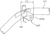
Therefore,, force down the height of framework, adopt the structure shown in Fig. 9~12 for obtaining necessary back buffer assembly length and being maintained specified value.
As Fig. 9, shown in Figure 10,101,101 of the left and right sides members that is made of tubing at the framework rear portion are setting up the transverse member 102 that is made of tubing; Welding carriage 103 at position near transverse member 102 1 sides; By this carriage 103, the upper end 104a with back buffer assembly 104 combines by bolt 105 grades.
The mounting portion of the upper end of posterior bumper 104 is placed high as far as possible position, for guaranteeing the length of back buffer assembly 104, as Figure 10, shown in Figure 11, with carriage 103 to oblique rear inclination welded joint on transverse member 102.
For carriage 103 and since with respect to the joint portion of transverse member 102, the bound fraction of back buffer parts 104 rearward has bigger biasing, so there is bigger twist moment to act on the carriage 103.Thereby, must thicken carriage 103 to guarantee high rigidity and high strength; Must set bigger bonding area to transverse member; For this reason, carriage 103 except the simple matrix 103a of portion of supporting back buffer assembly upper end, is to increase bonding area, must about wait big flange part 103b, 103b be set.
Therefore, above-mentioned existing structure, carriage 103 complex structures, material are thicker, complex-shaped, the relatively difficulty that therefore is shaped, cost is higher.
In addition, as as indicated in Figure 11, because carriage 103 fore-and-aft directions have certain-length, the fore-and-aft direction length L 1 of the frame sides installation portion of back buffer assembly 104 becomes big, the fore-and-aft direction length that is disposed at the helmet containing box 106 of this part is subjected to the restriction of this part, simultaneously, the space of the fore-and-aft direction at the rear of helmet containing box 106 diminishes, and is meeting difficulty aspect the configuration of the machine that is equipped on the rear.
Summary of the invention
The present invention promptly is to solve above-mentioned problem, the installation that its purpose is to provide such the small size motorcycle of back buffer assembly: simplify mounting structure of back buffer assembly; Simplify structure, making that part is installed; Reduce the part number; Cost-cutting; Simultaneously, reduce the length of the fore-and-aft direction of back buffer assembly installation portion as far as possible, make it to take in the width range of transverse member; Machine around the helmet containing box etc. there is not influence; Restriction lightens the carriage attenuation to the twist moment of carriage, and making may be more longways, to the framework length of setting back buffer assembly with exerting an influence.
For solving above-mentioned problem, the small size motorcycle that back buffer assembly has been installed provided by the present invention is, below pair of right and left framework member, supporting the power unit that can swing up and down with the trailing wheel one that constitutes by tabular component by back buffer assembly, it is characterized in that, setting up the transverse member that is made of tabular component between aforementioned pair of right and left framework member, the part of this transverse member is outstanding upward; Below the protrusion upward of aforementioned lateral member, be provided with carriage; Aforementioned protrusion is arranged on the part of a side of deflection aforementioned lateral member; The upper end of aforementioned back buffer assembly is installed on aforementioned bracket; The axis of aforementioned back buffer assembly disposes along the vertical direction.
According to the present invention, outstanding upward protrusion, the upper end of accommodating, supporting back buffer assembly on this part are set on a plate-like transverse member part; Can force down the height of framework left and right sides member, be disposed at the upper end support of back buffer assembly upper.The joint portion of transverse member and back buffer assembly upper end installation portion is each other in not biasing of fore-and-aft direction, so can not produce excessive twist moment to the carriage that connects both.In addition,, limited the length of the framework side bearing portion fore-and-aft direction of back buffer assembly, can set the capacity of helmet containing box etc. more greatly because the joint portion of installation portion on transverse member and the back buffer assembly does not produce configuration at fore-and-aft direction each other; And the space at back buffer assembly installation portion rear is also variable big, and this configuration to machine on every side is very favourable.
In addition, in the present invention, be to constitute transverse member with member with section channel form section that Open Side Down.
According to the present invention, be the channel form section that Open Side Down owing to constitute the tabular component of transverse member, as transverse member, replaced tubing with tabular component, can obtain the transverse member of high rigidity, the rigidity of back buffer assembly support is also high; And, owing to be downward open section, be actv. as the mounting base of back buffer assembly; In addition, owing to the upper end of back buffer assembly can be housed in the open section, and give prominence to upward, can guarantee the length of back buffer assembly.
In addition, the present invention is, between aforementioned pair of right and left framework, be equipped with helmet containing box in the position, the place ahead of aforementioned back buffer assembly, the rear portion is provided with the frame portion with aforementioned helmet containing box one above the upper end of aforementioned back buffer assembly, rear in aforementioned back buffer assembly sets fuel tank, simultaneously, the inlet of this fuel tank is opened in aforementioned portion.
According to the present invention, owing to can guarantee the space at back buffer assembly rear portion, so can be in its rear configuration fuel tank; In addition, because helmet containing box back space is big, can guarantee the fuel tank inlet is successfully placed this part.
Description of drawings
Fig. 1 is the outward appearance lateral plan of small size motorcycle; Fig. 2 is Fig. 1 small size motorcycle planar view; Fig. 3 is a mounting structure of back buffer assembly part outward appearance lateral plan of the present invention; Fig. 4 is the transverse member planar view; Fig. 5 is the arrow 5 direction views of Fig. 4; Fig. 6 is the 6-6 cutaway view of Fig. 4; Fig. 7 is that the supporting part that the back buffer assembly state has been installed amplifies sectional side view; Fig. 8 is that the arrow 8 of transverse member cross sectional drawing that the back buffer assembly state has been installed, Fig. 7 is to view; The existing mounting structure of back buffer assembly of small size motorcycle has been represented in Fig. 9~12, and Fig. 9 is the planar view that comprises the transverse member part of installation portion; Figure 10 is that the arrow 10 of Fig. 9 is to view; Figure 11 is that installation portion amplifies sectional side view; Figure 12 is that arrow 12 among Figure 11 is to view.
The specific embodiment
Bottom borrows accompanying drawing to be illustrated to example of the present invention.And drawing points to along symbol and watches.
Fig. 1 is a small size motorcycle outward appearance lateral plan; Fig. 2 is its planar view; Fig. 3 is the outward appearance lateral plan of installation constitution part of the present invention; Fig. 4 is the transverse member planar view; Fig. 5 is that the arrow 5 of Fig. 4 is to view; Fig. 6 is the 6-6 cutaway view of Fig. 4; Fig. 7 is installed with back buffer assembly state lower support partly to amplify sectional side view; Fig. 8 is installed with transverse member cross sectional drawing under the back buffer assembly state, is the figure that sees from the direction of the arrow 8 of Fig. 7.
Below, borrow Fig. 1, Fig. 2 that the outward appearance of small size motorcycle is described.In the drawings, the 1st, small size motorcycle; Shown in the dotted line among Fig. 1, the leading section at the low level front portion of framework 2 2a is being provided with steep corner and is managing 2b down to the front upper place bevelled; Support front fork 4 by the head pipe 2c that is located at its upper end, but supporting to steering front-wheel 3 on the front fork 4.On the steering clutch lever 4a that stretches out out above the head pipe 2c, the handlebar 5 of direction extension to the left and right is being set, front-wheel 3 travel directions are handled.
The pars intermedia 2d of framework 2 to the back upper place diagonally extending with steep corner from the back of the anterior 2a of framework 2; Rearward extend the rear portion 2e that constitutes seat rail obliquely to the back upper place gently from the upper end of pars intermedia 2d.Above-mentioned framework 2, except that the head pipe 2c of leading section, other all be from the beginning manage rearward by about 2 members constitute, though not shown among the figure, the appropriate location between the member of the left and right sides couples together with transverse member.
At the below an upper section of framework 2 pars intermedia 2d, supporting the power unit 6 that constitutes by driving engine 6a, drop-gear box 6b etc. swingably by connecting rod 6c, the trailing wheel 7 that constitutes drive wheel at the rear support of power unit 6; Clamping the back buffer assembly 8 that oleo gear etc. constitutes above the drop-gear box 6b rear portion and between the 2e of framework rear portion.Installation constitution about it will be told about in the back.
On the drop-gear box 6b of power unit 6, as shown in Figure 2, disposing the induction chamber 9 that extends along the overall width direction.This induction chamber 9, its air-breathing oral area 9a is disposed at a side of vehicle body, in illustrated embodiment, as shown in Figure 2, be disposed at the right side, and induction chamber body 9b and air-breathing oral area 9a picture are as shown in Figure 1, link up by ingress pipe 9c with auxiliary exhaust silencer 9d, induction chamber body 9b is communicated with airfilter 10, and this airfilter 10 is disposed at the opposite side of drop-gear box 6b, left side promptly shown in Figure 2 equally.Airfilter 10 is connected gasifier 11, and gasifier 11 is connected in the suction side of the cylinder head of driving engine by induction pipe 11a.
As shown in Figure 1 and Figure 2, between the left and right sides member of the anterior 2a of framework 2, be equipped with Fuel Tank 12; And for example shown in Figure 1, between 2e rear portion, the rear portion of framework 2, be equipped with fuel tank 13.Be equipped with storage battery 14 by a piping support in the place ahead of head pipe 2c.
The front of above-mentioned front part of vehicle head pipe 2c and about be covered with front shroud 15, also covered storage battery 14 simultaneously with this front shroud 15; At the rear of front shroud 15, be covered with steering clutch lever cover 16 in the back of head pipe 2c and the back of following pipe 2b.Be covered with by handlebar cover 17 around the handlebar 5; Be equipped with the lamp part 18 of head lamp, signal lamp etc. in the front of handlebar cover 17; Be equipped with metering unit 19 in the above.On front-wheel 3, be equipped with front fender apron 20.
Rearward extend low table pedal 21 from the bottom of front shroud 15, steering clutch lever cover 16, on pedal 21, constituted the leg rest portion of chaufeur.The upright upward seat post cover 22 that is provided with from the rear portion of pedal 21; Rear at this cover 22 is extending back cover 23 backward, by these the cover 22,23 whole be covered with framework pars intermedia 2d, rear portion 2e around.
Disposing seat 24 from seat post cover 22 tops to back cover 23, these seat 24 fore-and-aft directions are long, constitute the so-called tandem seat that two people take, and front stall 24a goes up and sits chaufeur, and back seat 24b goes up and sits with taking advantage of the people.
24 rear is equipped with tail-bracket 25 at the seat; On the front portion of tail-bracket 25, be provided with the handle 26 that the back seat occupant of a shape uses.
Below above-mentioned seat 24, setting helmet containing box 27.Helmet containing box 27 is covered around it by seat post cover 22, back cover 23.The rear portion of helmet containing box 27 as shown in Figure 7, these containing box 27 upward openings, but by seat 24 freely openables cover its opening above; The leading section at seat 24 becomes hinged so that lift, thereby constitutes the lid of helmet containing box 27.
Above trailing wheel 7, be covered with rear mudguard 28 with the rear.
As mentioned above, the rear portion 2e of aforesaid framework 2 as shown in Figure 1, becomes necessarily extension rearward obliquely to the back upper place; And for example Fig. 4, Fig. 5, shown in Figure 8, it is by with tubing 31,31 formations of left and right sides member along the a/s spacing distance configuration of overall width direction.
In Fig. 4, the upside of figure is a rear view of vehicle; Downside is a vehicle front.At left and right sides member 31, setting up transverse member 32 between 31 rear middle part, the profile of this transverse member has been shown among Fig. 4, Fig. 5, it is by the sheet material press forming, formation is to the channel form section of under shed, has last slice 32a, front and back sheet 32b, 32c, and, have respectively flange part 32d, the 32d of rear bending forward in the bottom of front and back sheet 32b, 32c.Thus, above-mentioned board member as transverse member, can be obtained high rigidity.Because sheet material is made trench section, also be shaped easily again.
At the two ends of transverse member 32, be integrally formed with arcuation joint fastener 32e, 32e, with the first half of the established part of this part and left and right sides member 31,31 overlap, weld together; Again as shown in Figure 3, Figure 4, at joint fastener 32e, the base portion of 32e is integrally formed with platform shape joint fastener 32f, 32f; This part is welded in the medial surface of left and right sides member 31,31 established parts.
In addition, at the pars intermedia of the overall width direction of transverse member 32, with the 32d of said flange portion, the part of 32d extends out along fore-and-aft direction installation sheet 32g, 32h is set; Mounting support the leading section of aforementioned rear mudguard 28 on installation sheet 32h, and the part of helmet containing box 27 bottoms by installation sheet 32g mounting support.
In the partisan part of the left and right sides of above-mentioned transverse member 32 member 31,31, promptly (among Fig. 5, see from the front to occupy the right side by vehicle left side part in the drawings; See on the left of the residence from the rear among Fig. 8), be provided with protrusion 33 upward.
The transverse member with protrusion 33 32 of top can be made of steel plate press forming spare, also can be made of aluminium alloy casting spare.
The bottom 8a of aforementioned back buffer assembly 8 combines with bracket piece 6d on the drop-gear box 6b rear portion that is located at aforementioned power unit 6; Back buffer assembly 8 is as Fig. 3, shown in Figure 7, by the body 8b that constitutes with oleo gear, bar 8d, recoil spring 8c, end towards formations such as Rubber Parts (バ Application Off ° ス ト Star Ha ° ラ バ-) 8e.The upper end of bar 8d has the hub of the installation 8f of portion, with aforementioned bracket 34 belows of this installation hub 8f of portion below one is engaged in the protrusion 33 of aforementioned lateral member 32, sandwich this carriage about 34 sheet 34b, between the 34b, pierce into bolt 35 from the side, make it to combine with nut 39.
In the side that the bolt 35 of the protrusion 33 of transverse member 32 inserts a side, as Fig. 4, shown in Figure 8, be provided with bolt hole 36, by this through hole 36 bolt 35 is inserted from vehicle left side, the two lateral plate 34b that hub 8f is held on carriage 34 are installed in the upper end of back buffer assembly 8, between the 34b, implement to install.
As shown in Figure 3, at the rear portion of the left and right sides member 31,31 that constitutes framework rear portion 2e, be provided with the strut member 37 of aforementioned tail-bracket 25.Part 38 in Fig. 4, Fig. 5 is wire clamps of supporting wirning harness.
From the above mentioned, the installation hub 8f of portion of back buffer assembly 8 upper ends, by carriage 34 mounting supports in be located at part by transverse member 32 1 sides, and outstanding upward protrusion 33 in.Because accommodating, carriage 34 is installed in the groove downward in the protrusion 33 that projects upwards, so not direction configuration forwards, backwards of carriage 34; And its height and position can be set in high as far as possible position.
Thereby the position that the hub 8f of portion is installed is positioned at above the projecting height part of outstanding upward protrusion 33, like this, can guarantee the specified length of back buffer assembly; And the whole height of the height of left and right sides member 31,31 and transverse member 32 can not uprise.
Owing to constitute the installation hub 8f of portion of back buffer assembly 8 upper end installation portions, can not produce the biasing of carriage 34 fore-and-aft directions and be positioned at transverse member 32 under, can not produce the back buffer assembly twist moment such to the existing structure of carriage 34; Thereby, to the burden of carriage 34 and existingly relatively diminished, compared with prior art, can make carriage 34 attenuation, structure is simplified, and is shaped easily, and welding is also simple easy on the transverse member 32.
As shown in Figure 7, the rear wall 27a of aforementioned helmet containing box 27 is positioned at the place ahead of the mounting portion of back buffer assembly 8, and since the length of the fore-and-aft direction of mounting portion shorten compared with the existing and be size L, thereby the length of the fore-and-aft direction of helmet containing box 27 can be set more greatly.
The space phase strain at rear, back buffer assembly mounting portion is big, thereby as mentioned above, such as under the situation of carrying 2 cycle engines, fuel tank 13 that can volume ratio is bigger is disposed at rear, back buffer assembly mounting portion; In addition, rear at the rear wall 27a of helmet containing box 27, be wholely set the matrix frame 27b of portion, the anterior filling tube 13a that is disposed at the fuel tank 13 at rear can be curved the bottom 27c of L type ground, can make the 13b of injection portion of upper end run through 27c ground, bottom in the face of the 27b of frame portion in the face of this part.
Thus, the inlet of fuel tank 13 can be located at the rear portion of helmet containing box 27, and can obtain the bigger space of inlet part.
As previously mentioned, helmet containing box 27 constitutes its lid by seat 24, thereby, start seat 24, open the fuel tank injection 13b of portion, uncover gets final product oiling.As previously mentioned, at this moment because this part space is strengthened, the oiling operation can be carried out at an easy rate.
In Fig. 7, on the rearward outstanding installation sheet 32h that the pars intermedia of the overall width direction of aforementioned lateral member 32 is provided with, the leading section installation sheet 28b of the anterior 28a of rear mudguard 28 is installed, is supporting with screw.
The present invention is made of above-mentioned, can bring into play following effect.
According to the present invention, between pair of right and left framework member, setting up the transverse member that constitutes by tabular component, make the part of this transverse member outstanding upward, below the outstanding upward part of transverse member, carriage is set, the bottom is installed, is supported on the upper end mounting support of the back buffer assembly on the oscillating type power unit on this carriage, therefore, the upper end installation portion of back buffer assembly can be accommodated and mounting support below the protrusion upward of transverse member; Force down the height of framework left and right sides member; The transverse member whole height that sets up is therebetween forced down and the same level of left and right sides member, and the upper end that can keep back buffer assembly is in a high position.
Thereby, on one side can must be lower with the height setting of framework; The length of back buffer assembly can be adapted to specified length necessary on the energy disperser that is maintained at rear wheel suspension on one side.Thereby the pooling feature that can be fully guaranteed, riding comfortable small size motorcycle.
In addition, the joint portion of transverse member and posterior bumper component upper ends installation portion, direction can not produce biasing forwards, backwards mutually, can not produce excessive twist moment to the carriage that connects both, the load of the installation bracket of back buffer assembly reduces, thereby, can be with thin material fabrication and installation carriage, can adopt the also simple member of simple shape, structure, and bonding area is also little than existing, carriage is made simple and easy, carriage engages also simple and easy, constituent part is also few, in a word, can obtain the installation constitution of light and cheap back buffer assembly.
According to the present invention, owing to constitute transverse member with the member with section channel form section that Open Side Down, as transverse member, the tabular component of the press forming spare of use steel plate sheet material or aluminum alloy system Casting Parts etc. replaces tubing; Can obtain the transverse member of high rigidity; Also improved the rigidity of back buffer assembly support.And owing to become downward open section, also be actv. as the mounting base of back buffer assembly; Mounting portion, upper end, the carriage of back buffer assembly can be contained in the recess of under shed, in addition, owing to the upper end of back buffer assembly can be contained in the open section, protrusion projects upwards in addition, can guarantee to obtain necessity of back buffer assembly and enough length.
According to the present invention, configuration helmet containing box between the pair of right and left framework.Owing in helmet containing box, in position, aforementioned back buffer assembly rear, be provided with the inlet of the fuel tank that is disposed at helmet containing box rear, at first, can guarantee to be disposed at the capacity of back buffer assembly the place ahead, helmet containing box on every side; Simultaneously, can fully guarantee the space at back buffer assembly rear portion; Therefore, can be at this rear configuration fuel tank; Simultaneously, the fuel tank inlet can be placed the bigger space at helmet containing box rear portion, guarantee that this part is easy to use.
Claims (3)
1. the small size motorcycle that back buffer assembly is installed below pair of right and left framework member, is supporting the power unit that can swing up and down with the trailing wheel one by back buffer assembly, it is characterized in that,
Setting up the transverse member that is made of tabular component between aforementioned pair of right and left framework member, the part of this transverse member is outstanding upward;
Below the protrusion upward of aforementioned lateral member, be provided with carriage;
Aforementioned protrusion is arranged on the part of a side of deflection aforementioned lateral member;
The upper end of aforementioned back buffer assembly is installed on aforementioned bracket;
The axis of aforementioned back buffer assembly disposes along the vertical direction.
The installation of recording and narrating by claim 1 small size motorcycle of back buffer assembly, it is characterized in that the aforementioned lateral member constitutes by having the member of section to the channel form section of under shed.
The installation of recording and narrating by claim 1 small size motorcycle of back buffer assembly, it is characterized in that, between aforementioned pair of right and left framework, be equipped with helmet containing box in the position, the place ahead of aforementioned back buffer assembly, the rear portion is provided with the frame portion with aforementioned helmet containing box one above the upper end of aforementioned back buffer assembly, rear in aforementioned back buffer assembly sets fuel tank, simultaneously, the inlet of this fuel tank is opened in aforementioned portion.
Applications Claiming Priority (3)
| Application Number | Priority Date | Filing Date | Title |
|---|---|---|---|
| JP355674/97 | 1997-12-24 | ||
| JP35567497A JP4153069B2 (en) | 1997-12-24 | 1997-12-24 | Rear cushion unit mounting structure for scooter type vehicles |
| JP355674/1997 | 1997-12-24 |
Publications (2)
| Publication Number | Publication Date |
|---|---|
| CN1220957A CN1220957A (en) | 1999-06-30 |
| CN1123476C true CN1123476C (en) | 2003-10-08 |
Family
ID=18445195
Family Applications (1)
| Application Number | Title | Priority Date | Filing Date |
|---|---|---|---|
| CN98125785A Expired - Fee Related CN1123476C (en) | 1997-12-24 | 1998-12-23 | Mounting structure of back buffer assembly for small-sized motorcycle-type vehicle |
Country Status (4)
| Country | Link |
|---|---|
| JP (1) | JP4153069B2 (en) |
| CN (1) | CN1123476C (en) |
| IT (1) | IT1303178B1 (en) |
| TW (1) | TW377323B (en) |
Families Citing this family (3)
| Publication number | Priority date | Publication date | Assignee | Title |
|---|---|---|---|---|
| DE602004004053T2 (en) * | 2003-12-25 | 2007-04-26 | Honda Motor Co., Ltd. | support element |
| JP5410238B2 (en) * | 2009-02-18 | 2014-02-05 | 本田技研工業株式会社 | Saddle riding vehicle |
| BR112014013199B1 (en) * | 2011-12-02 | 2021-02-02 | Honda Motor Co., Ltd. | vehicle frame structure |
Citations (5)
| Publication number | Priority date | Publication date | Assignee | Title |
|---|---|---|---|---|
| US5020847A (en) * | 1990-02-27 | 1991-06-04 | Shih Chun Jih | Scooter body open frame of loop form with a lateral beam joining longitudinal, laterally spaced side bars |
| JPH03197289A (en) * | 1989-12-26 | 1991-08-28 | Yamaha Motor Co Ltd | Rear wheel suspension device for scooter type motorcycle |
| CN1089553A (en) * | 1992-07-31 | 1994-07-20 | 雅马哈发动机株式会社 | The mounting structure of the integrated oscillating type driving engine of two-wheeled motor vehicle |
| EP0757951A2 (en) * | 1995-08-08 | 1997-02-12 | ITALJET S.p.A. | Rear shock absorbing device for scooters |
| JPH09323690A (en) * | 1996-06-05 | 1997-12-16 | Honda Motor Co Ltd | Body structure in scooter type vehicle |
-
1997
- 1997-12-24 JP JP35567497A patent/JP4153069B2/en not_active Expired - Fee Related
-
1998
- 1998-10-20 TW TW087117350A patent/TW377323B/en not_active IP Right Cessation
- 1998-11-25 IT IT000991 patent/IT1303178B1/en active IP Right Grant
- 1998-12-23 CN CN98125785A patent/CN1123476C/en not_active Expired - Fee Related
Patent Citations (5)
| Publication number | Priority date | Publication date | Assignee | Title |
|---|---|---|---|---|
| JPH03197289A (en) * | 1989-12-26 | 1991-08-28 | Yamaha Motor Co Ltd | Rear wheel suspension device for scooter type motorcycle |
| US5020847A (en) * | 1990-02-27 | 1991-06-04 | Shih Chun Jih | Scooter body open frame of loop form with a lateral beam joining longitudinal, laterally spaced side bars |
| CN1089553A (en) * | 1992-07-31 | 1994-07-20 | 雅马哈发动机株式会社 | The mounting structure of the integrated oscillating type driving engine of two-wheeled motor vehicle |
| EP0757951A2 (en) * | 1995-08-08 | 1997-02-12 | ITALJET S.p.A. | Rear shock absorbing device for scooters |
| JPH09323690A (en) * | 1996-06-05 | 1997-12-16 | Honda Motor Co Ltd | Body structure in scooter type vehicle |
Also Published As
| Publication number | Publication date |
|---|---|
| JP4153069B2 (en) | 2008-09-17 |
| ITTO980991A1 (en) | 2000-05-25 |
| CN1220957A (en) | 1999-06-30 |
| JPH11180368A (en) | 1999-07-06 |
| TW377323B (en) | 1999-12-21 |
| IT1303178B1 (en) | 2000-10-30 |
Similar Documents
| Publication | Publication Date | Title |
|---|---|---|
| CN1754754A (en) | Motorcycle | |
| CN1827459A (en) | Body frame of motorcycle | |
| US8281889B2 (en) | Seat structure for vehicle and vehicle incorporating same | |
| CN100349779C (en) | Wheeled vehicle with stand | |
| CN1317156C (en) | Bodywork structure of two-wheel motor | |
| CN1652964A (en) | Seat support structure for saddle-mounting type vehicles | |
| CN1096380C (en) | Mounting structure of bicycle body cover | |
| CN1223487C (en) | Windscreen device motor bicycle | |
| CN1269682C (en) | Front cover mounting mechanism of two-wheel motorcycle | |
| CN1840410A (en) | Body structure of automotive bicycle | |
| CN1976842A (en) | Motor vehicle | |
| CN1123476C (en) | Mounting structure of back buffer assembly for small-sized motorcycle-type vehicle | |
| CN1443677A (en) | Fuel tank supporting structure for motorcycle | |
| CN1079759C (en) | Small motorcycle body structure | |
| CN1259213C (en) | Seat structure for a saddle-type vehicle | |
| CN1597423A (en) | Luggage carrier device | |
| CN1903647A (en) | Low-floor vehicle | |
| CN1211247C (en) | Car body frame of small-sized motorcycle type vehicle | |
| CN1292953C (en) | Helmet accepting structure of saddle bearing vehicle | |
| CN1706705A (en) | Wheeled vehicle with foot guide | |
| CN1196622C (en) | Engine mounting structure of small-sized motorcycle type vehicle | |
| CN101898606B (en) | Motorcycle | |
| CN1116194C (en) | Installation structure of back buffer parts of small-sized motorcycle type vehicle | |
| CN1130297C (en) | Body structure for small motorcycle | |
| CN1145569C (en) | Small-size motor-cycle |
Legal Events
| Date | Code | Title | Description |
|---|---|---|---|
| C10 | Entry into substantive examination | ||
| SE01 | Entry into force of request for substantive examination | ||
| C06 | Publication | ||
| PB01 | Publication | ||
| C14 | Grant of patent or utility model | ||
| GR01 | Patent grant | ||
| CF01 | Termination of patent right due to non-payment of annual fee | ||
| CF01 | Termination of patent right due to non-payment of annual fee |
Granted publication date: 20031008 Termination date: 20171223 |