Disclosure of Invention
The invention aims to provide a rail grinding angle grouping method suitable for various types of grinding equipment so as to solve the problems in the background technology.
In order to achieve the purpose, the invention provides the following technical scheme: a rail grinding angle grouping method suitable for various types of grinding equipment comprises the following steps: the method comprises the following steps:
firstly, determining a grinding direction: no matter a rail grinding vehicle with multi-head marshalling is adopted or a grinding tool is manually adopted, the advancing direction is confirmed to be the basis for confirming the grindstone marshalling according to the condition of the rail and the required working edge;
second, the large angle always precedes: in order to reduce the edges and corners generated by angle staggering as much as possible, mode grouping of grinding stones is required to be carried out from large to small (inside and outside the steel rail) at the foremost end of the grinding direction, and the principle is still kept when the grinding stones on the inside and the outside are interacted; the angle end point of each module and the angle starting point of the next module are crossed, and the crossed degree refers to a table I;
thirdly, setting the recommended power: (in the case of a large machine in the form of a rail grinding wagon, the machine conditions are hydraulic drive and six-inch grinding stone, and under these conditions, PWM100 is 17kw and PWM0 is 2.5kw, and the output power of the grinding stone is slightly different for each machine condition, so that the output power of the same small machine is converted for reference only for the same small machine)
The recommended power starts at a minimum of 55(10.745kw) to a maximum of 90(15.55 kw);
the dust yield of PMW 60(11.2kw) (including) and the following PWM (pulse width modulation) is less than or equal to 60(11.2kw) is extremely low, and the following contents can be basically carried out only on a new rail: pre-polishing before opening, and derusting and deslagging a new rail;
the dust emission amount of PMW 60(11.2kw) (not included) to 75(13.375kw) (included) 60 < PWM ≦ 75 is shown in the following table, and the common daily rail grinding operation can be carried out, wherein the PWM is generally recommended to be set to about 70;
the dust output is high (corresponding special treatment should be carried out) due to PMW 75(13.375kw) (not included) and PWM (more than 75(13.375kw) < PWM is less than or equal to 90(15.55kw), the power selected in a special state is not recommended to be used, and the blue light phenomenon is easily generated on the steel rail;
fourth, weaving of module
[ Delta ] marshalling proposal under general conditions (general maintenance)
When the sanding angle exceeds-40 °, the sanding area is substantially in the vicinity of the same position as the angle increases, and sanding work in a non-special case is substantially meaningless, so that a general sanding pattern group is maintained in a range of-40 ° to 40 °.
When marshalling, the marshalling is generally decremented or incremented by reference to the following table: (watch one)
Note in the table:
A. when the distances between the grinding heads are-40 and 20, and the distances between the grinding heads are +40 and 20, the decreasing (increasing) number of the angles can be 3 degrees as the interval according to the situation, but 2 degrees is generally used as the standard, and 1 degree can also be used but only used as an angle compensation means when grouping;
B. when the-20 < s > < 10 and the +20 > < s > +10 ranges, the decreasing (increasing) number of the angle is generally based on 2 degrees, and 1 degree can also be used but only used as an angle compensation means when grouping;
C. when the-3 is less than or equal to the range of settings less than +3, the decreasing (increasing) number of the angle can be generally based on 1 degree, 0.5 degree is carefully used as an interval, and the 0.5 degree can be used as grouping when the light band is finely adjusted;
② Delta marshalling suggestion under general conditions (full face maintenance)
When the grinding work needs to perform full-face grinding, polishing and correction, the grinding range needs to extend the grinding angle to the non-working edge of the outer edge and the working edge of the inner side. The polishing angle range is more than minus 25 degrees and less than 45 degrees;
when marshalling, the marshalling is generally decremented or incremented by reference to the following table: (watch two)
Note in the table:
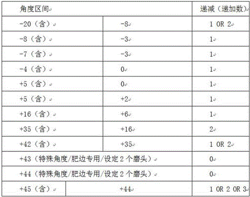
A. when the distances between the distances are-25 and not more than-7 and the distances between the distances are +45 and not less than +17, the decreasing (increasing) number of the angles is that 3 degrees are used as intervals according to stepwise decrease, then 2 degrees are used, and then 1 degree is used; larger decreasing (increasing) numbers of angles should be used in large angle variations and vice versa;
B. when the angle is within the range of +17 > settings ≧ 3, the decreasing (increasing) number of the angle is generally based on 2 degrees, and 1 degree can also be used but only used as an angle compensation means in grouping;
C. when the range of-7 < settings < -2, the decreasing (increasing) number of the angle can be generally based on 1 degree;
D. when the range of-2 < settings < +2.5, the decreasing (increasing) number of the angle is 0.5 degrees, which is a special use, but the light band made by the use is wider, and the convergence light band can be properly adjusted;
③ marshalling suggestion under delta general conditions (fat edge maintenance)
When the trimming is corrected and removed according to the grinding work requirement, according to the experience provided by the manufacturer:
aiming at larger fat edges; the function needs to work under 2 degrees of fixed angle of 44 degrees and 43 degrees, the root is eliminated, and the fat edge automatically falls off after the vehicle passes through the function for a plurality of times; the polishing angle range is more than minus 20 degrees and less than 45 degrees;
trimming aiming at slight fat edge/action edge; the module is generally carried out by using a larger angle, but is not commonly used; the reference set angle may be used from +75 ° to +45 °; however, this setting is only smeared out to fat edges, and different settings lead to widely differing effects depending on the degree of match between power/grinding speed, and may be accompanied by negative effects of rail damage;
when marshalling, the marshalling is generally decremented or incremented by reference to the following table: (watch III)
Note in the table:
A. when the steel rail is used at +44 and +43, the two angles are used for breaking the root of the steel rail fat edge, so that the fat edge automatically falls under the repeated action of the wheels.
B. The present reference formation does not take into account the correction amount of the optical band, and therefore does not correct the parameter setting of the optical band.
Reserved setting of delta light band
The space between-2.5 and +2.0 is not opened (not set), which is higher than the ground tread, and the light band is formed after the vehicle drives for many times. The specific reservation setting can be determined by the line condition.
Fifthly, recommended setting of power:
PWM is 65/60 the setting of the lightest weight, basically cannot see too big effect, but is enough for testing a new module, and belongs to the module test grinding;
the PWM is 75/70 common grinding power, and the power of the effect is basically ensured;
PWM 80/85 is not commonly used, but can handle ripple/fault power that is not easily removed;
sixthly, setting the grinding working speed and the grinding power in a matching way:
principle: suggested 4-6KM/H boost, with PWM75-85
75/70/65 PWM adapted to 5KM/H
6KM/H adaptive PWM 75/80/85
Seventhly, setting the number of the groups:
considering the requirements of field work (factors to be comprehensively considered include effective operation time, operation amount, driving speed and the like), a full-section coverage is proposed to be divided into 5 groups (20 heads in each group, 10 heads on each side and the like in other cases, and the like), and under the condition, the polishing operation of 1 kilometer can be generally completed within 2 hours of effective time.
The rail grinding wagon is generally large mechanical equipment for grinding by using a cup-shaped grinding stone (6 inches and below), and typical examples include, but are not limited to, Harsco rail RGH series (10C, 20C, 30C wagon) or Jinying heavy industry CMC series (10C, 20C, 30C wagon).
The hand-held rail refiner is typically a hand-held rail refiner that performs the grinding operation using a cup-shaped grindstone (6 inch and below), typically but not limited to SCHMIDT schhmidt, germany or similar equipment manufactured by Geismar, france.
Compared with the prior art, the invention has the beneficial effects that:
the invention has the advantages of safety, reliability, wide application range (suitable for 43Kg/m, 50Kg/m, 60Kg/m, 75Kg/m and other types of steel rails and various grinding devices), continuous grinding surface, less smooth small planes, filling a certain gap of field practice, and quick and simple deployment.
Detailed Description
The technical solutions in the embodiments of the present invention will be clearly and completely described below with reference to the drawings in the embodiments of the present invention, and it is obvious that the described embodiments are only a part of the embodiments of the present invention, and not all of the embodiments. All other embodiments, which can be derived by a person skilled in the art from the embodiments given herein without making any creative effort, shall fall within the protection scope of the present invention.
In the description of the present invention, it should be noted that the terms "vertical", "upper", "lower", "horizontal", and the like indicate orientations or positional relationships based on those shown in the drawings, and are only for convenience of describing the present invention and simplifying the description, but do not indicate or imply that the referred device or element must have a specific orientation, be constructed in a specific orientation, and be operated, and thus, should not be construed as limiting the present invention.
In the description of the present invention, it should also be noted that, unless otherwise explicitly stated or limited, the terms "disposed," "mounted," "connected," and "connected" are to be construed broadly and may be, for example, fixedly connected, detachably connected, or integrally connected; can be mechanically or electrically connected; they may be connected directly or indirectly through intervening media, or they may be interconnected between two elements. The specific meanings of the above terms in the present invention can be understood by those skilled in the art according to specific situations.
Referring to fig. 1 to 8, the present invention provides a technical solution:
a rail grinding angle grouping method suitable for various types of grinding equipment comprises the following steps: the method comprises the following steps:
firstly, determining a grinding direction: no matter a rail grinding vehicle with multi-head marshalling is adopted or a grinding tool is manually adopted, the advancing direction is confirmed to be the basis for confirming the grindstone marshalling according to the condition of the rail and the required working edge;
second, the large angle always precedes: in order to reduce the edges and corners generated by angle staggering as much as possible, mode grouping of grinding stones is required to be carried out from large to small (inside and outside the steel rail) at the foremost end of the grinding direction, and the principle is still kept when the grinding stones on the inside and the outside are interacted; the angle end point of each module and the angle starting point of the next module are crossed, and the crossed degree refers to a table I;
thirdly, setting the recommended power: (in the case of a large machine in the form of a rail grinding wagon, the machine conditions are hydraulic drive and six-inch grinding stone, and under these conditions, PWM100 is 17kw and PWM0 is 2.5kw, and the output power of the grinding stone is slightly different for each machine condition, so that the output power of the same small machine is converted for reference only for the same small machine)
The recommended power starts at a minimum of 55(10.745kw) to a maximum of 90(15.55 kw);
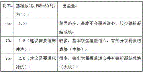
the dust yield of PMW 60(11.2kw) (including) and the following PWM (pulse width modulation) is less than or equal to 60(11.2kw) is extremely low, and the following contents can be basically carried out only on a new rail: pre-polishing before opening, and removing rust and slag of a new rail;
the dust emission amount of PMW 60(11.2kw) (not included) to 75(13.375kw) (included) 60 < PWM ≦ 75 is shown in the following table, and the common daily rail grinding operation can be carried out, wherein the PWM is generally recommended to be set to about 70;
the dust output is high (corresponding special treatment should be carried out) due to PMW 75(13.375kw) (not included) and PWM (more than 75(13.375kw) < PWM is less than or equal to 90(15.55kw), the power selected in a special state is not recommended to be used, and the blue light phenomenon is easily generated on the steel rail;
fourth, weaving of module
[ Delta ] marshalling proposal under general conditions (general maintenance)
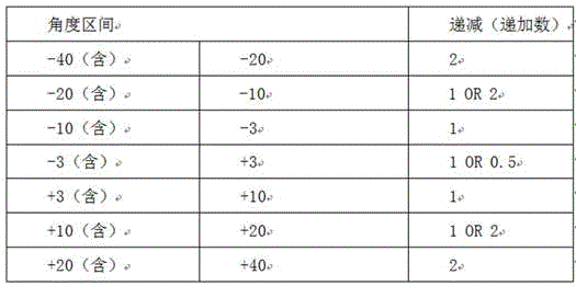
When the sanding angle exceeds-40 °, the sanding area is substantially in the vicinity of the same position as the angle increases, and sanding work in a non-special case is substantially meaningless, so that a general sanding pattern group is maintained in a range of-40 ° to 40 °.
When marshalling, the marshalling is generally decremented or incremented by reference to the following table: (watch one)
Note in the table:
A. when the distances between the grinding heads are-40 and 20, and the distances between the grinding heads are +40 and 20, the decreasing (increasing) number of the angles can be 3 degrees as the interval according to the situation, but 2 degrees is generally used as the standard, and 1 degree can also be used but only used as an angle compensation means when grouping;
B. when the-20 & ltor & gt, settings & lt-10 & gt and the +20 & gtsettings & gt, the decreasing (increasing) number of the angle is generally based on 2 degrees, and 1 degree can also be used but only used as an angle compensation means when grouping;
C. when the-3 is less than or equal to the range of settings less than +3, the decreasing (increasing) number of the angle can be generally based on 1 degree, 0.5 degree is carefully used as an interval, and the 0.5 degree can be used as grouping when the light band is finely adjusted;
② marshalling proposals under the general case (full-face maintenance)
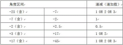
When the grinding work needs to carry out full-section grinding, polishing and correction, the grinding range needs to expand the grinding angle to the non-working edge of the outer edge and the working edge of the inner side. The polishing angle range is from-25 degrees to 45 degrees;
when marshalling, the marshalling is generally decremented or incremented by reference to the following table: (watch two)
Note in the table:
A. when the settings are more than or equal to-25 and less than-7 and more than +45 and more than or equal to +17, the decreasing (increasing) number of the angles is gradually decreased, and 3 degrees is used as an interval first, then 2 degrees is used, and then 1 degree is used; larger decreasing (increasing) numbers of angles should be used in large angle variations and vice versa;
B. when the angle is within the range of +17 > settings ≧ 3, the decreasing (increasing) number of the angle is generally based on 2 degrees, and 1 degree can also be used but only used as an angle compensation means in grouping;
C. when the range of-7 < settings < -2, the decreasing (increasing) number of the angle can be generally based on 1 degree;
D. when the range of-2 < settings < +2.5, the decreasing (increasing) number of the angle is 0.5 degrees, which is a special use, but the light band made by the use is wider, and the convergence light band can be properly adjusted;
③ marshalling suggestion under delta general conditions (fat edge maintenance)
When the dressing is corrected and removed according to the grinding work requirement, according to the experience provided by the manufacturer:
aiming at larger fat edges; the function needs to work under 2 fixed degrees of 44 degrees and 43 degrees to eliminate the root, and the fat edge automatically falls off after the vehicle passes through the function for a plurality of times; the polishing angle range is more than minus 20 degrees and less than 45 degrees;
trimming aiming at slight fat edge/action edge; the module is generally carried out by using a larger angle, but is not commonly used; the reference set angle may be used from +75 ° to +45 °; however, this setting is only smeared out to fat edges, and depending on the degree of match between power/sanding speed, different settings can lead to widely differing effects, possibly with the negative effect of damaging the rail;
when marshalling, the marshalling is generally decremented or incremented by reference to the following table: (watch III)
Note in the table:
A. when the steel rail is used at +44 and +43, the two angles are used for breaking the root of the steel rail fat edge, so that the fat edge automatically falls under the repeated action of the wheels.
B. The present reference formation does not take into account the correction amount of the optical band, and therefore does not correct the parameter setting of the optical band.
Reserved setting of delta light band
The space between-2.5 and +2.0 is not opened (not set), which is higher than the ground tread, and the light band is formed after the vehicle drives for many times. The specific reservation setting can be determined by the line condition.
Fifthly, recommended setting of power:
PWM is 65/60 the setting of the lightest weight, basically cannot see too big effect, but is enough for testing a new module, and belongs to the module test grinding;
the PWM is 75/70 common grinding power, and the power of the effect is basically ensured;
PWM 80/85 is not commonly used, but can handle ripple/fault power that is not easily removed;
sixthly, setting the grinding working speed and the grinding power in a matching way:
principle: suggested 4-6KM/H boost, with PWM75-85
75/70/65 PWM adapted to 5KM/H
6KM/H adaptive PWM 75/80/85
Seventhly, setting the number of the groups:
considering the requirements of field work (factors to be comprehensively considered include effective operation time, operation amount, driving speed and the like), a full section is proposed to be covered and divided into 5 groups (each group comprises 20 heads, each side comprises 10 machines, and other conditions can be automatically converted in an equal proportion), and under the condition, the grinding operation of 1 kilometer can be generally ensured to be completed within 2 hours of effective time.
Further, the rail grinding wagon is generally a large machine for grinding with a cup-shaped grinding stone (6 inches and below), and typical examples include, but are not limited to, the american hardco rail RGH series (10C, 20C, 30C wagon) or the eagle rework CMC series (10C, 20C, 30C wagon).
The hand-held rail refiner is typically a hand-held rail refiner that performs the grinding operation using a cup-shaped grindstone (6 inch and below), typically but not limited to SCHMIDT schhmidt, germany or similar equipment manufactured by Geismar, france.
The working principle is as follows: in actual work, the method is divided into manual operation and equipment (steel rail grinding wagon) operation, and the steps are different.
When using manual operation, (see fig. 2) first determine the grinding direction according to the track conditions (working edge to be ground, wear conditions, etc.), at least five workers of hand-held track refiner (the power of the machine is determined in advance according to the working requirements) are arranged in sequence along the working track, the machine interval of each worker is at least two meters, the worker closest to the grinding working area is numbered 1, and so on, the last worker is numbered 5. Secondly, according to the specific working condition, determining to polish back and forth for several times and the angle range of each polishing to perform module organization, for example: in general maintenance, referring to table one, the selected angle range of the first grinding is from +40 to +28 degrees, the grinding heads of the hand-held track refiner of five workers have a difference of 2-3 degrees, according to the principle that a large angle is in front, the grinding head angle of the worker No. 1 is 40 degrees, the grinding head angle of the worker No. 2 is 37 degrees, and the like, the grinding head angle of the worker No. 5 is 28 degrees; after the angle is determined, the workers advance (the speed is estimated according to the power of the machine), the No. 1 worker firstly reaches the end point of the working area, the grinding head is firstly lifted off the track, the rest is done in the same way, the No. 5 worker finally reaches the end point of the working area, the grinding head is finally lifted off the track, five workers turn to the direction, the No. 5 worker becomes the No. 1 worker, the No. 1 worker becomes the No. 5 worker, and the next grinding is prepared.
The grinding head angle of the worker 1 is-40 degrees, the grinding head angle of the worker 2 is-37 degrees, and the like, and the grinding head angle of the worker 5 is-28 degrees; after the angle is determined, the workers advance (the speed is estimated according to the power of the machine), the worker No. 1 firstly reaches the end point of the working area, the grinding head is firstly lifted away from the track, the rest is done in the same way, the worker No. 5 finally reaches the end point of the working area, the grinding head is finally lifted away from the track, five persons turn to the direction, the worker No. 5 becomes the worker No. 1, the worker No. 1 becomes the worker No. 5, and the next grinding is prepared.
By analogy, the selection angle range of the third grinding is between +30 and +18 degrees, the selection angle range of the fourth grinding is between-30 and-18 degrees, the selection angle range of the fifth grinding is between +20 and +8 degrees, the selection angle range of the sixth grinding is between-20 and-8 degrees, and the selection angle range of the seventh grinding is between +10 and-10 degrees.
According to the angle calculation, the whole working surface of the track can be covered only by going and returning about seven times, and at the moment, attention needs to be paid to the intersection between the angle end point of each module and the angle start point of the next module, and the intersection degree refers to a table I (see figure 3).
When the equipment (steel rail grinding wagon) is used, most domestic equipment adopts 10C/20C/30C vehicles of the American hardco rail RGH series, and the difference is that the 10C vehicle is provided with ten grinding heads and is arranged on two sides of the same wagon body, and 5 sides of each vehicle body are only used as one group; 20C has twenty abrasive heads arranged on both sides of the vehicle body with 10 abrasive heads on each side as a set, and 30C has thirty abrasive heads arranged on both sides of the vehicle body with 15 abrasive heads on each side as a set. This is explained here with the most common 20C example.
The first step is as follows: firstly, according to the track condition (working edge, abrasion condition and the like needing to be polished), determining the polishing direction, driving the steel rail polishing car to a preset position (see attached figure 4), and according to the specification parameters of the existing polishing car, combining the work needing to be done (light, medium and heavy), converting and determining the set power. For example, the mechanical equipment conditions are: a hydraulically driven, six inch stone grinder, under which conditions PWM100 ═ 17kw, PWM0 ═ 2.5 kw; the equipment is used for ordinary daily rail grinding operation, and the PWM is generally recommended to be set to about 70.
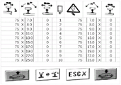
The second step is that: secondly, according to the specific working condition, determining to polish back and forth for several times and the angle range of each polishing to perform module organization, for example: for general maintenance, referring to table one, selecting +40 to +18 degrees for first grinding, wherein each difference is 2-3 degrees between a group of ten grinding heads of the track grinding wagon, and according to the principle that a large angle is in front, the angle of a grinding head No. 1 is +40 degrees, the angle of a grinding head No. 2 is +37 degrees, and so on, and the angle of a grinding head No. 10 is +18 degrees; all grinding heads are arranged on a grinding trolley device at the bottom of the trolley body, the angle of the grinding heads is controlled by a system of the trolley body, and the angle is specifically shown in the attached drawings of 5, 6, 7, 8 and 9, and the interface is a jupiter interface of a rail grinding trolley of the U.S. hardco rail RGH series 10C/20C/30C;
in the figure:
the first row and column icons are power, unit PWM;
the icons in the first row and the second column are angles, the unit is degrees, and X represents the deviation of the working surface (the inner side and the outer side of the track);
the icons in the first row and the third column are sideslip in mm, wherein X represents the working face deflection (inside and outside of the rail);
the icon of the first row and the fourth column is a grinding head, and the number below the column is the number of the grinding head;
the fifth, sixth and seventh columns of the first row represent the status of another set of grinding heads, here exemplified by a 20C vehicle, with two symmetrical sets of grinding heads, the number of grinding heads on each side depending on the number of grinding heads of the apparatus.
After the weaving is finished, the rail grinding wagon advances along the determined grinding direction, and the last grinding head stops when reaching the end point of the working area. The track grinding vehicle can run forwards and backwards, so that the track grinding vehicle can directly run backwards without steering to carry out secondary grinding, the grinding head No. 1 is changed into the grinding head No. 10, the grinding head No. 10 is changed into the grinding head No. 1, and the like, the working edge of the track grinding vehicle is certainly the other edge opposite to the first time, the angle is-40 to-18 degrees, the angle of the grinding head No. 1 is-40 degrees, the angle of the grinding head No. 2 is-37 degrees, and the like, and the angle of the grinding head No. 10 is-18 degrees; after the angle is determined, the rail grinding wagon advances along the second grinding direction, and the last grinding head stops when reaching the end point of the working area to prepare for the next grinding.
By analogy, the selection angle range of the third grinding is between +20 and +8 degrees, the selection angle range of the fourth grinding is between-20 and-8 degrees, and the selection angle range of the fifth grinding is between +10 and-10 degrees.
The third step: matched setting of grinding speed and power
Principle: suggested 4-6KM/H push, with PWM75-85
75/70/65 PWM adapted to 5KM/H
6KM/H adaptive PWM 75/80/85
The fourth step: setting of number of formation
Considering the requirements of field work (factors to be comprehensively considered include effective operation time, operation amount, traveling speed and the like), when the rail grinding vehicle is used, a full-section coverage is proposed to be divided into 5 groups (20 heads in each group, 10 heads on each side, and the like in other cases can be automatically converted in an equal proportion), and under the condition, the grinding operation of 1 kilometer can be generally completed within 2 hours of effective time. When man-hour is adopted, each hand-held refiner calculates a grinding head, and a group of five persons need time which is several times of that of a steel rail grinding wagon to finish the operation.
Although embodiments of the present invention have been shown and described, it will be appreciated by those skilled in the art that changes, modifications, substitutions and alterations can be made in these embodiments without departing from the principles and spirit of the invention, the scope of which is defined in the appended claims and their equivalents.