CN112303783A - Ventilation equipment with lighting panel and use method - Google Patents
Ventilation equipment with lighting panel and use method Download PDFInfo
- Publication number
- CN112303783A CN112303783A CN202011266253.5A CN202011266253A CN112303783A CN 112303783 A CN112303783 A CN 112303783A CN 202011266253 A CN202011266253 A CN 202011266253A CN 112303783 A CN112303783 A CN 112303783A
- Authority
- CN
- China
- Prior art keywords
- ventilation
- frame
- rod
- magnetic
- pull
- Prior art date
- Legal status (The legal status is an assumption and is not a legal conclusion. Google has not performed a legal analysis and makes no representation as to the accuracy of the status listed.)
- Withdrawn
Links
Images


Classifications
-
- F—MECHANICAL ENGINEERING; LIGHTING; HEATING; WEAPONS; BLASTING
- F24—HEATING; RANGES; VENTILATING
- F24F—AIR-CONDITIONING; AIR-HUMIDIFICATION; VENTILATION; USE OF AIR CURRENTS FOR SCREENING
- F24F7/00—Ventilation
- F24F7/04—Ventilation with ducting systems, e.g. by double walls; with natural circulation
- F24F7/06—Ventilation with ducting systems, e.g. by double walls; with natural circulation with forced air circulation, e.g. by fan positioning of a ventilator in or against a conduit
- F24F7/065—Ventilation with ducting systems, e.g. by double walls; with natural circulation with forced air circulation, e.g. by fan positioning of a ventilator in or against a conduit fan combined with single duct; mounting arrangements of a fan in a duct
-
- F—MECHANICAL ENGINEERING; LIGHTING; HEATING; WEAPONS; BLASTING
- F24—HEATING; RANGES; VENTILATING
- F24F—AIR-CONDITIONING; AIR-HUMIDIFICATION; VENTILATION; USE OF AIR CURRENTS FOR SCREENING
- F24F13/00—Details common to, or for air-conditioning, air-humidification, ventilation or use of air currents for screening
- F24F13/08—Air-flow control members, e.g. louvres, grilles, flaps or guide plates
- F24F13/10—Air-flow control members, e.g. louvres, grilles, flaps or guide plates movable, e.g. dampers
- F24F13/14—Air-flow control members, e.g. louvres, grilles, flaps or guide plates movable, e.g. dampers built up of tilting members, e.g. louvre
- F24F13/1426—Air-flow control members, e.g. louvres, grilles, flaps or guide plates movable, e.g. dampers built up of tilting members, e.g. louvre characterised by actuating means
-
- F—MECHANICAL ENGINEERING; LIGHTING; HEATING; WEAPONS; BLASTING
- F24—HEATING; RANGES; VENTILATING
- F24F—AIR-CONDITIONING; AIR-HUMIDIFICATION; VENTILATION; USE OF AIR CURRENTS FOR SCREENING
- F24F13/00—Details common to, or for air-conditioning, air-humidification, ventilation or use of air currents for screening
- F24F13/08—Air-flow control members, e.g. louvres, grilles, flaps or guide plates
- F24F13/10—Air-flow control members, e.g. louvres, grilles, flaps or guide plates movable, e.g. dampers
- F24F13/14—Air-flow control members, e.g. louvres, grilles, flaps or guide plates movable, e.g. dampers built up of tilting members, e.g. louvre
- F24F13/15—Air-flow control members, e.g. louvres, grilles, flaps or guide plates movable, e.g. dampers built up of tilting members, e.g. louvre with parallel simultaneously tiltable lamellae
-
- F—MECHANICAL ENGINEERING; LIGHTING; HEATING; WEAPONS; BLASTING
- F24—HEATING; RANGES; VENTILATING
- F24F—AIR-CONDITIONING; AIR-HUMIDIFICATION; VENTILATION; USE OF AIR CURRENTS FOR SCREENING
- F24F13/00—Details common to, or for air-conditioning, air-humidification, ventilation or use of air currents for screening
- F24F13/08—Air-flow control members, e.g. louvres, grilles, flaps or guide plates
- F24F13/10—Air-flow control members, e.g. louvres, grilles, flaps or guide plates movable, e.g. dampers
- F24F13/14—Air-flow control members, e.g. louvres, grilles, flaps or guide plates movable, e.g. dampers built up of tilting members, e.g. louvre
- F24F13/1426—Air-flow control members, e.g. louvres, grilles, flaps or guide plates movable, e.g. dampers built up of tilting members, e.g. louvre characterised by actuating means
- F24F2013/148—Air-flow control members, e.g. louvres, grilles, flaps or guide plates movable, e.g. dampers built up of tilting members, e.g. louvre characterised by actuating means with magnets
Abstract
The invention discloses ventilation equipment with an illumination panel, which belongs to the technical field of ventilation equipment and comprises a ventilation frame, wherein the left side of the ventilation frame is uniformly hinged with a wind shield, a cross fixing frame is longitudinally arranged in the inner cavity of the ventilation frame, a motor is arranged in the cross fixing frame, the output end of the motor is connected with a rotating shaft through a speed reducer, fan blades are arranged on the rotating shaft, a second fixing seat is arranged at the top end of the ventilation frame, a rotating rod is transversely arranged in the second fixing seat, a driving disc is arranged at one end of the left side of the rotating rod, a first fixing seat is arranged at the top end of the ventilation frame on the left side of the second fixing seat, a pull rod transversely penetrates through the first fixing seat, and a pull block is fixedly connected at one end of the left side of the pull rod. Thereby the size of the wind is balanced, and the condition that the wind is big to cause the indoor shade cold or the ventilation effect is not good when the wind is small is avoided.
Description
Technical Field
The invention relates to the technical field of ventilation equipment, in particular to ventilation equipment with an illumination panel and a using method of the ventilation equipment.
Background
Present house generally all needs to ventilate, so channel ventilation equipment, current ventilation equipment who has lighting panel is when ventilating, can not adjust the size of wind, thereby can cause the big time of wind the indoor cloudy cold or the not good condition of wind hour ventilation effect, in addition, when external wind is great, current ventilation equipment who has lighting panel can not be timely the vent of closing, wind can make the dust raise enter into the room through ventilation equipment, thereby lead to the condition of the interior a large amount of dusts of deposit, be difficult to the clearance. To this end, we propose a ventilation device with an illumination panel and a method of use.
Disclosure of Invention
The present invention is directed to a ventilation device with an illumination panel and a method of use to solve the problems set forth in the background art.
In order to achieve the purpose, the invention provides the following technical scheme: a ventilation device with an illumination panel comprises a ventilation frame, wherein a wind shield is uniformly hinged to the left side of the ventilation frame, a first spring is connected between the wind shield and the left side of the ventilation frame, a cross fixing frame is longitudinally installed in an inner cavity of the ventilation frame, a motor is installed in the cross fixing frame and is in linear connection with an external power supply, the output end of the motor is connected with a rotating shaft through a speed reducer, a fan blade is installed on the rotating shaft, a cross bearing frame is installed at the other end of the rotating shaft, a second fixing seat is installed at the top end of the ventilation frame, a rotating rod is transversely installed in the second fixing seat, a driving disc is installed at one end of the left side of the rotating rod, a driven belt pulley is sleeved on the periphery of the rotating rod, a main belt pulley is sleeved on the periphery of the rotating shaft, the, the utility model discloses a wind shield, including fixing base one, pull rod, fixing base one, pull rod left side one end fixedly connected with draw the piece, draw and lie in the peripheral cover of pull rod between piece and the fixing base one and have spring two, a fixing base left side lies in the ventilation frame top and installs the montant, the fixed pulley is installed on the montant top, the stay cord has connected gradually on the deep bead, the stay cord other end passes the fixed pulley and draws the piece to be connected.
Preferably, a driving mechanism is installed at the top end of the ventilation frame, an upper cross rod is connected to the driving mechanism, a buffering mechanism is installed at the bottom end of the ventilation frame, a lower cross rod is connected to the buffering mechanism, and the other ends of the upper cross rod and the lower cross rod are connected with the same sealing plate.
Preferably, actuating mechanism includes rack, lower rack and gear, it is in drawing a piece bottom to go up rack fixed connection, rack fixed connection is on last horizontal pole down, the gyro wheel is evenly installed to lower rack bottom, montant right side fixedly connected with dead lever, the gear is installed on the dead lever, the gear respectively with last rack and lower rack intermeshing.
Preferably, buffer gear includes fixing base three, the sheer pole runs through fixing base three, three right sides of fixing base are located the peripheral fixed cover of sheer pole and have connect the extrusion piece, it has spring three to lie in the peripheral cover of sheer pole between extrusion piece and the fixing base three, sheer pole left side one end fixedly connected with stopper.
Preferably, the periphery of the driving disc is uniformly provided with two magnetic discs, the two magnetic discs are symmetrical along a horizontal line, the magnetic discs are matched with the magnetic blocks, and the magnetism of the magnetic discs is opposite to that of the magnetic blocks.
Preferably, the use method of the ventilation device with the lighting panel comprises the following steps:
s1: when the ventilating fan is used, the motor is started, and the rotating shaft drives the fan blades to rotate by the motor, so that the aim of ventilation is fulfilled;
s2: the rotation of the rotating shaft drives the main belt pulley to rotate, the main belt pulley drives the rotating rod to rotate through the flat belt and the secondary belt pulley, the rotating rod rotates to enable the driving disc to rotate, the magnetic disc intermittent attraction magnetic blocks on the driving disc move rightwards, the pull rod moves leftwards and rightwards in a reciprocating mode under the action of the second spring, and therefore the pull rope intermittently pulls the wind shield, the wind shield can be intermittently opened and closed, and ventilation is uniform;
s3: when the outside wind is large, the motor is turned off, the magnetic block moves rightwards under the attraction of the magnetic disc and is attracted on the magnetic disc, the pull block pulls the pull rope to close the wind shield, the upper rack on the pull block moves rightwards at the same time, the lower rack drives the upper cross rod to move leftwards through the rotation of the gear, and therefore the upper cross rod drives the sealing plate to block the ventilation opening on the right side of the ventilation frame, and the effect of no ventilation is achieved.
Compared with the prior art, the invention has the beneficial effects that: the invention is provided with the magnetic block, the pull rod, the pull rope and the driving disc, the intermittent magnetic block is attracted by the rotation of the driving disc, so that the pull rod reciprocates left and right, the pull rod intermittently opens and closes the wind shield through the pull rope, the wind is balanced, and the condition that the indoor cold or small wind ventilation effect is poor due to large wind is avoided; be provided with the closing plate, the closing plate can be sealed with the ventilation frame on, has avoided can blowing into a large amount of dusts to the room when external wind is great to lead to the condition of a large amount of dusts of indoor deposit.
Drawings
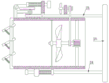
FIG. 1 is a schematic structural view of a front portion of the present invention;
FIG. 2 is a schematic front view of the present invention;
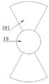
FIG. 3 is a side view of a driving disk according to the present invention;
FIG. 4 is a schematic view of the driving mechanism of the present invention;
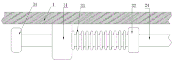
FIG. 5 is a schematic view of a buffering mechanism according to the present invention.
In the figure: 1. a ventilation frame; 2. a wind deflector; 3. a first spring; 4. a cross-shaped fixing frame; 5. a motor; 6. a rotating shaft; 7. a fan blade; 8. a cross bearing bracket; 9. a vertical rod; 10. a fixed pulley; 11. a first fixed seat; 12. a pull rod; 13. pulling the block; 14. a second spring; 15. a magnetic block; 16. pulling a rope; 17. a second fixed seat; 18. a rotating rod; 19. a drive disc; 191. a magnetic disk; 20. a primary pulley; 21. a secondary pulley; 22. a flat belt; 23. an upper cross bar; 24. a lower cross bar; 25. a sealing plate; 26. a lower rack; 27. a roller; 28. an upper rack; 29. fixing the rod; 30. a gear; 31. a third fixed seat; 32. extruding the block; 33. a third spring; 34. and a limiting block.
Detailed Description
The technical solutions in the embodiments of the present invention will be clearly and completely described below with reference to the drawings in the embodiments of the present invention, and it is obvious that the described embodiments are only a part of the embodiments of the present invention, and not all of the embodiments. All other embodiments, which can be derived by a person skilled in the art from the embodiments given herein without making any creative effort, shall fall within the protection scope of the present invention.
Referring to fig. 1, the present invention provides a technical solution: a ventilation device with an illumination panel comprises a ventilation frame 1, wherein a wind shield 2 is uniformly hinged on the left side of the ventilation frame 1, a first spring 3 is connected between the wind shield 2 and the left side of the ventilation frame 1, when the wind shield 2 inclines, the first spring 3 is in a normal state, a cross fixing frame 4 is longitudinally arranged in the inner cavity of the ventilation frame 1, a motor 5 is arranged in the cross fixing frame 4, the motor 5 is in linear connection with an external power supply, the output end of the motor 5 is connected with a rotating shaft 6 through a speed reducer, a fan blade 7 is arranged on the rotating shaft 6, a cross bearing frame 8 is arranged at the other end of the rotating shaft 6, a second fixing seat 17 is arranged at the top end of the ventilation frame 1, a rotating rod 18 is transversely arranged in the second fixing seat 17, a driving disc 19 is arranged at one end of the left side of the rotating rod 18, a driven belt pulley 21, two 17 left sides of fixing base are located the ventilation frame 1 top and install fixing base 11, transversely run through in the fixing base 11 and have pull rod 12, 12 right side one end fixedly connected with magnetic path 15 of pull rod, 12 left side one end fixedly connected with of pull rod draws piece 13, it has two springs 14 to draw the peripheral cover of 12 pull rods to lie in between piece 13 and the fixing base 11, two springs 14 play the recovery effect to pull rod 12, 11 left sides of fixing base are located ventilation frame 1 top and install montant 9, fixed pulley 10 is installed on montant 9 top, the deep bead has connected gradually stay cord 16 on 2, the stay cord 16 other end passes fixed pulley 10 and is connected with drawing piece 13, fixed pulley 10 makes more smooth and easy when 16 receipts of stay cord draw.
Referring to fig. 2, a driving mechanism is installed at the top end of the ventilation frame 1, an upper cross bar 23 is connected to the driving mechanism, a buffering mechanism is installed at the bottom end of the ventilation frame 1, a lower cross bar 24 is connected to the buffering mechanism, the other ends of the upper cross bar 23 and the lower cross bar 24 are connected to a same sealing plate 25, and the area of the sealing plate 25 is larger than the cross-sectional area of the ventilation frame 1.
Referring to fig. 4, the driving mechanism includes an upper rack 28, a lower rack 26 and a gear 30, the upper rack 28 is fixedly connected to the bottom end of the pull block 13, the lower rack 26 is fixedly connected to the upper cross bar 23, rollers 27 are uniformly installed at the bottom end of the lower rack 26, the rollers 27 make the lower rack 26 move more smoothly, a fixing rod 29 is fixedly connected to the right side of the vertical rod 9, the gear 30 is installed on the fixing rod 29, the gear 30 is respectively engaged with the upper rack 28 and the lower rack 26, when the upper rack 28 moves to the right, the gear 30 rotates clockwise, so that the lower rack 26 moves to the left, and when the upper rack 28 moves to the left, the gear 30 rotates counterclockwise, so that the lower rack 26 moves to the right.
Referring to fig. 5, the buffering mechanism includes a third fixing seat 31, the lower cross bar 24 penetrates through the third fixing seat 31, an extruding block 32 is fixedly sleeved on the right side of the third fixing seat 31 and located on the periphery of the lower cross bar 24, a third spring 33 is sleeved on the periphery of the lower cross bar 24 between the extruding block 32 and the third fixing seat 31, the third spring 33 plays a role in buffering when the lower cross bar 24 moves rightwards, and plays a role in recovering when the lower cross bar 24 moves leftwards, and a limit block 34 is fixedly connected to one end of the left side of the lower cross bar.
Referring to fig. 1 and 3, the magnetic discs 191 are uniformly installed on the periphery of the driving disk 19, two magnetic discs 191 are arranged, the two magnetic discs 191 are symmetrical along a horizontal line, the magnetic discs 191 are matched with the magnetic blocks 15, the magnetic properties of the magnetic discs 191 and the magnetic blocks 15 are strong, and the magnetic properties of the magnetic discs 191 are opposite to the magnetic properties of the magnetic blocks 15, so that the magnetic discs 191 can attract the magnetic blocks 15.
A use method of a ventilation device with an illumination panel comprises the following steps:
s1: when the ventilating fan is used, the motor 5 is started, and the motor 5 enables the rotating shaft 6 to drive the fan blades 7 to rotate, so that the aim of ventilation is fulfilled;
s2: the rotation of the rotating shaft 6 drives the main belt pulley 20 to rotate, the main belt pulley 20 drives the rotating rod 18 to rotate through the flat belt 22 and the secondary belt pulley 21, the rotating rod 18 rotates to enable the driving disc 19 to rotate, the magnetic disc 191 on the driving disc 19 intermittently attracts the magnetic block 15 to move rightwards, the pull rod 12 reciprocates leftwards and rightwards under the action of the second spring 14, and therefore the pull rope 16 intermittently pulls the wind shield 2, the wind shield 2 can be intermittently opened and closed, and ventilation is uniform;
s3: when the outside wind is large, the motor 5 is turned off, at this time, the magnetic block 15 moves rightwards under the attraction of the magnetic disc 191 and is attracted on the magnetic disc 191, the pull block 13 also pulls the pull rope 16 to close the wind shield 2, meanwhile, the upper rack 28 on the pull block 13 moves rightwards, the lower rack 26 drives the upper cross rod 23 to move leftwards through the rotation of the gear 30, and therefore the upper cross rod 23 drives the sealing plate 25 to block the ventilation opening on the right side of the ventilation frame 1, and the effect of no ventilation is achieved.
Although embodiments of the present invention have been shown and described, it will be appreciated by those skilled in the art that changes, modifications, substitutions and alterations can be made in these embodiments without departing from the principles and spirit of the invention, the scope of which is defined in the appended claims and their equivalents.
Claims (6)
1. A ventilation device with an illumination panel, comprising a ventilation frame (1), characterized in that: the ventilating frame is characterized in that a wind shield (2) is evenly hinged to the left side of the ventilating frame (1), a first spring (3) is connected between the wind shield (2) and the left side of the ventilating frame (1), a cross fixing frame (4) is longitudinally installed in an inner cavity of the ventilating frame (1), a motor (5) is installed in the cross fixing frame (4), the motor (5) is in linear connection with an external power supply, an output end of the motor (5) is connected with a rotating shaft (6) through a speed reducer, fan blades (7) are installed on the rotating shaft (6), a cross bearing frame (8) is installed at the other end of the rotating shaft (6), a second fixing seat (17) is installed at the top end of the ventilating frame (1), a rotating rod (18) is transversely installed in the second fixing seat (17), a driving disc (19) is installed at one end of the, a main belt pulley (20) is sleeved on the periphery of the rotating shaft (6), the main belt pulley (20) is in transmission connection with a driven belt pulley (21) through a flat belt (22), the left side of the second fixed seat (17) is positioned at the top end of the ventilation frame (1) and is provided with a first fixed seat (11), a pull rod (12) transversely penetrates through the first fixed seat (11), one end of the right side of the pull rod (12) is fixedly connected with a magnetic block (15), a pull block (13) is fixedly connected with one end of the left side of the pull rod (12), a second spring (14) is sleeved on the periphery of the pull rod (12) between the pull block (13) and the first fixing seat (11), a vertical rod (9) is arranged on the left side of the first fixed seat (11) and positioned at the top end of the ventilation frame (1), the top end of the vertical rod (9) is provided with a fixed pulley (10), the wind shield (2) is sequentially connected with a pull rope (16), the other end of the pull rope (16) penetrates through the fixed pulley (10) to be connected with the pull block (13).
2. A ventilating device with an illuminating panel according to claim 1, wherein: the ventilating frame is characterized in that a driving mechanism is installed at the top end of the ventilating frame (1), an upper cross rod (23) is connected to the driving mechanism, a buffering mechanism is installed at the bottom end of the ventilating frame (1), a lower cross rod (24) is connected to the buffering mechanism, and the other ends of the upper cross rod (23) and the lower cross rod (24) are connected with the same sealing plate (25).
3. A ventilating device with an illuminating panel according to claim 2, wherein: actuating mechanism includes rack (28), lower rack (26) and gear (30), go up rack (28) fixed connection and draw piece (13) bottom, lower rack (26) fixed connection is on last horizontal pole (23), gyro wheel (27) are evenly installed to lower rack (26) bottom, montant (9) right side fixedly connected with dead lever (29), install on dead lever (29) gear (30), gear (30) respectively with last rack (28) and lower rack (26) intermeshing.
4. A ventilating device with an illuminating panel according to claim 3, wherein: buffer gear includes fixing base three (31), fixing base three (31) are run through in sheer pole (24), the fixed cover that is located sheer pole (24) on fixing base three (31) right side has been cup jointed extrusion piece (32), it has spring three (33) to lie in sheer pole (24) peripheral cover between extrusion piece (32) and fixing base three (31), sheer pole (24) left side one end fixedly connected with stopper (34).
5. A ventilating device with an illuminating panel according to claim 4, wherein: the magnetic disc (191) is uniformly arranged on the periphery of the driving disc (19), two magnetic discs (191) are arranged, the two magnetic discs (191) are symmetrical along a horizontal line, the magnetic discs (191) are matched with the magnetic blocks (15), and the magnetism of the magnetic discs (191) is opposite to that of the magnetic blocks (15).
6. Use of a ventilation device with an illumination panel according to any one of claims 1 to 5, characterized in that:
s1: when the ventilating fan is used, the motor (5) is started, and the rotating shaft (6) drives the fan blades (7) to rotate by the motor (5), so that the aim of ventilation is fulfilled;
s2: the rotating shaft (6) rotates to drive the main belt pulley (20) to rotate, the main belt pulley (20) drives the rotating rod (18) to rotate through the flat belt (22) and the secondary belt pulley (21), the rotating rod (18) rotates to enable the driving disc (19) to rotate, the magnetic disc (191) on the driving disc (19) intermittently attracts the magnetic block (15) to move rightwards, the pull rod (12) reciprocates leftwards and rightwards under the action of the second spring (14), and therefore the pull rope (16) intermittently pulls the wind shield (2), the wind shield (2) can be intermittently opened and closed, and ventilation is uniform;
s3: when the external wind is large, the motor (5) is turned off, the magnetic block (15) moves rightwards under the attraction of the magnetic disc (191) and is attracted to the magnetic disc (191), the pull block (13) also pulls the pull rope (16) to close the wind shield (2), meanwhile, the upper rack (28) on the pull block (13) moves rightwards, the lower rack (26) drives the upper cross rod (23) to move leftwards through the rotation of the gear (30), and therefore the upper cross rod (23) drives the sealing plate (25) to block the ventilation opening on the right side of the ventilation frame (1), and the effect of no ventilation is achieved.
Priority Applications (1)
| Application Number | Priority Date | Filing Date | Title |
|---|---|---|---|
| CN202011266253.5A CN112303783A (en) | 2020-11-13 | 2020-11-13 | Ventilation equipment with lighting panel and use method |
Applications Claiming Priority (1)
| Application Number | Priority Date | Filing Date | Title |
|---|---|---|---|
| CN202011266253.5A CN112303783A (en) | 2020-11-13 | 2020-11-13 | Ventilation equipment with lighting panel and use method |
Publications (1)
| Publication Number | Publication Date |
|---|---|
| CN112303783A true CN112303783A (en) | 2021-02-02 |
Family
ID=74334289
Family Applications (1)
| Application Number | Title | Priority Date | Filing Date |
|---|---|---|---|
| CN202011266253.5A Withdrawn CN112303783A (en) | 2020-11-13 | 2020-11-13 | Ventilation equipment with lighting panel and use method |
Country Status (1)
| Country | Link |
|---|---|
| CN (1) | CN112303783A (en) |
Cited By (1)
| Publication number | Priority date | Publication date | Assignee | Title |
|---|---|---|---|---|
| CN114353174A (en) * | 2022-01-26 | 2022-04-15 | 德州市美达空调设备有限公司 | Noise reduction device for central air-conditioning fan coil |
-
2020
- 2020-11-13 CN CN202011266253.5A patent/CN112303783A/en not_active Withdrawn
Cited By (1)
| Publication number | Priority date | Publication date | Assignee | Title |
|---|---|---|---|---|
| CN114353174A (en) * | 2022-01-26 | 2022-04-15 | 德州市美达空调设备有限公司 | Noise reduction device for central air-conditioning fan coil |
Similar Documents
| Publication | Publication Date | Title |
|---|---|---|
| CN210422041U (en) | Sunshine room convenient to ventilate and sunshade | |
| CN201843456U (en) | Window capable of opening and closing at regular time | |
| CN201593354U (en) | Auto-controlled opening-closing type window | |
| CN112303783A (en) | Ventilation equipment with lighting panel and use method | |
| CN112593805A (en) | Household window capable of being automatically opened and closed according to weather conditions | |
| CN209145097U (en) | A kind of ventilation type curtain wall structure | |
| CN209369676U (en) | A kind of Novel rainproof vent shutter | |
| CN201704890U (en) | Automatically controlled opening and closing skylight | |
| CN209413701U (en) | A kind of projecting top-hung window according to room temperature automation opening and closing | |
| CN201588485U (en) | Concealed window capable of automatic control of opening/closing | |
| CN208251929U (en) | A kind of aluminum alloy doors and windows | |
| CN207212136U (en) | One kind lifting door and window | |
| CN204098744U (en) | Vent window ventilating mechanisms on a kind of grain depot | |
| CN203081134U (en) | Window capable of being automatically opened and closed | |
| CN201714275U (en) | Curtain capable of keeping out wind and rain | |
| CN113738681A (en) | Electric roller shutter window for shading and sealing heat preservation of fan and using method of electric roller shutter window | |
| CN211818884U (en) | Novel window | |
| CN2864048Y (en) | Electric exhausting window | |
| CN212154539U (en) | Ventilation window | |
| CN211900265U (en) | Outward opening sunshade window | |
| CN2890271Y (en) | Convenient energy-saving remotely-controlled window | |
| CN111810003A (en) | Formaldehyde detector capable of automatically opening and closing window | |
| CN202561947U (en) | Electric control bilayer shutter sound insulation and noise reduction curtain wall ventilator | |
| CN2538139Y (en) | Convection continuous ventilation lighting house for animals and poultry | |
| CN112282609A (en) | Door and window with fresh air ventilation function |
Legal Events
| Date | Code | Title | Description |
|---|---|---|---|
| PB01 | Publication | ||
| PB01 | Publication | ||
| SE01 | Entry into force of request for substantive examination | ||
| SE01 | Entry into force of request for substantive examination | ||
| WW01 | Invention patent application withdrawn after publication | ||
| WW01 | Invention patent application withdrawn after publication |
Application publication date: 20210202 |