CN1123021C - Energy accumulator for step switch - Google Patents
Energy accumulator for step switch Download PDFInfo
- Publication number
- CN1123021C CN1123021C CN99807730A CN99807730A CN1123021C CN 1123021 C CN1123021 C CN 1123021C CN 99807730 A CN99807730 A CN 99807730A CN 99807730 A CN99807730 A CN 99807730A CN 1123021 C CN1123021 C CN 1123021C
- Authority
- CN
- China
- Prior art keywords
- balladeur train
- switch
- guide
- accumulator
- tighten
- Prior art date
- Legal status (The legal status is an assumption and is not a legal conclusion. Google has not performed a legal analysis and makes no representation as to the accuracy of the status listed.)
- Expired - Fee Related
Links
Images


Classifications
-
- H—ELECTRICITY
- H01—ELECTRIC ELEMENTS
- H01H—ELECTRIC SWITCHES; RELAYS; SELECTORS; EMERGENCY PROTECTIVE DEVICES
- H01H9/00—Details of switching devices, not covered by groups H01H1/00 - H01H7/00
-
- H—ELECTRICITY
- H01—ELECTRIC ELEMENTS
- H01H—ELECTRIC SWITCHES; RELAYS; SELECTORS; EMERGENCY PROTECTIVE DEVICES
- H01H9/00—Details of switching devices, not covered by groups H01H1/00 - H01H7/00
- H01H9/0005—Tap change devices
- H01H9/0027—Operating mechanisms
-
- H—ELECTRICITY
- H01—ELECTRIC ELEMENTS
- H01H—ELECTRIC SWITCHES; RELAYS; SELECTORS; EMERGENCY PROTECTIVE DEVICES
- H01H3/00—Mechanisms for operating contacts
- H01H3/22—Power arrangements internal to the switch for operating the driving mechanism
- H01H3/30—Power arrangements internal to the switch for operating the driving mechanism using spring motor
- H01H3/3052—Linear spring motors
Abstract
The present invention relates to an energy accumulator for a step switch, comprising a slide which can be pulled upwards and a latchable switch slide that follows the movement of the pull-up slide in an elastic manner upon release. The pull-up slide and switch slide are can be respectively displaced in the longitudinal direction of a guide rod. The pull-up slide and the switch slide have a respective guide roller on one side and have a guide contour on the opposite side, whereby the guide roller of the pull-up slide is guided in the guide contour of the switch slide and vice versa.
Description
Technical field
The present invention relates to a kind of accumulator that is used for step switch.By DE-PS 19 56 369 known this accumulators.
Background technology
Step switch is used for switching without interruption also thereby being used for the voltage adjustment between the different tapping of stepping adjustable transformer.Real load is switched and must be realized as far as possible fast, so step switch or its load switch are established an accumulator usually.Continuous and slow drive shaft rotating tightens and discharges kinetic energy at it with being released the back phase step type subsequently accumulator by means of one.
Accumulator by DE-PS 19 56 369 known a kind of this type.It has a balladeur train that compresses that tightens a balladeur train and a breech locked; Between these two balladeur trains, be provided with the spring that is designed to compression spring.Tighten balladeur train and compress balladeur train and be provided with flange, their inboard builds up each other mutually can be at this compression spring of clamping between the flange that tightens balladeur train and the flange that compresses balladeur train.Tighten balladeur train in this case and handle by means of the eccentric disc on driving shaft, that is with respect to compressing the direction motion of balladeur train towards it.The compression spring that therefore will be between them clamps.Arrive its terminal location when tightening balladeur train, that is spring is when being clamped farthest, cancellation compressing the breech lock of balladeur train and making it implement rapid movement.This lengthwise movement fast converts the switch crank to by the roller pin of guiding in compressing a groove of balladeur train that is switch shaft is to rotatablely move fast equally, and itself then handles the load switch switch crank.
By the accumulator of DE-PS 28 06 282 known another kind of all fours, even it also is equipped with the attachment device that assurance also can reliably be switched when low temperature.
At last, by the also known a kind of accumulator of DE-PS 39 19 596, wherein, the eccentric wheel on driving shaft is in the same horizontal plane basically with the compression spring that is used for accumulation of energy, acts on to avoid strength asymmetricly.
But all these known accumulators all have a series of shortcomings.At first be their structure more complicated and form by numerous part.Tightening balladeur train and compressing balladeur train of particularly can vertically moving proposed high and the highest required precision by means of vertical guiding of parallel guide rod in both sides, and these both require at the depth of parallelism of guide rod itself and dimensional accuracy also at the supporting arrangement of these two balladeur trains on these guide rods.In addition, implement the dual conversion of the direction of motion in known accumulator: rotatablely moving of driving shaft converts the lengthwise movement of accumulator to, and its lengthwise movement transforms back into rotatablely moving so that handle step switch of switch shaft again after release.Do so very complicated, but and not only be not suitable for but also unnecessary for the step switch of original moving linearly and its load switch.It should be noted that in addition these known accumulator designs are used for working in the circuit-breaker oil of step switch.To this, people must know the common oiling of known step switch, not only play dielectric at switch inside oil in this case, and the function of the machine components of lubricated motion is arranged.Yet, also more known to recently air or gas step switch, therefore wherein lubricated in this way possibility as dielectric work.For these application scenarios, be unfavorable by above-mentioned desired high-precision vertical guiding of prior art and supporting arrangement.
Summary of the invention
The accumulator that the purpose of this invention is to provide a kind of the above-mentioned type, it simple in structure is even formed and also can be worked safely and reliably under the condition of air or gas by the least possible and part that be convenient to make.
This purpose reaches by the accumulator that is used for step switch that starts described type, and it comprises two parallel guide rod; Wherein tighten balladeur train and only on a guide rod, guide, and the switch balladeur train is only guided on another root guide rod; Described two guide rods are fixed on the independent base plate; In addition, establish two pawl bars on base plate, they can overcome the power deflection of a spring and open and the latch switch balladeur train.According to another feature of the present invention, when tightening balladeur train and arrive its new terminal location, can cancel the breech lock of switch balladeur train.According to another feature of the present invention, tightening balladeur train has first guide wheel and at opposite side a guide groove that extends along the direction of motion is arranged in a side; As the switch balladeur train.According to another feature of the present invention, the guide wheel that tightens balladeur train is guided in the guide groove of switch balladeur train, and the guide wheel of switch balladeur train is guided in tightening the guide groove of balladeur train.
By the outstanding advantage of accumulator of the present invention at first is that the mechanical structure of whole parts is very simple.The major part of this accumulator is three flat parts, that is base plate, tightens balladeur train and switch balladeur train, and the latter is equivalent to the balladeur train that compresses of prior art, and they all can particularly advantageously be designed to simple sheet member.Needed ammunition feed spring props up the backstop by usefulness, is designed to the plate tongue or the clamping plate of direct forming bending on corresponding part in a simple manner.Another advantage by accumulator of the present invention is that not only tightening balladeur train but also compressing balladeur train respectively is that a side is guided, and is in addition supported each other and guided by self on fixing guide rod.Simple mode tolerance balancing thus.In addition, whole device is for lubricating without any specific (special) requirements.At last, in this accumulator, directly spread out of as the motion of handling load switch or step switch by the lengthwise movement that switch coupling joint will compress balladeur train in simple mode.
Description of drawings
Illustrate in greater detail the present invention by accompanying drawing as example below.Wherein:
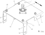
Fig. 1 is by accumulator perspective view of the present invention;
Fig. 2 represents the base plate of this accumulator separately, a) is vertical view b) be upward view;
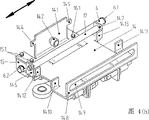
Fig. 3 represents the balladeur train that tightens of this accumulator separately, a) is vertical view b) be upward view; And
Fig. 4 represents the switch balladeur train of this accumulator separately, a) is vertical view b) be upward view.
Embodiment
Describing in detail by before the accumulator structure of the present invention, being also pointed out that among the whole Fig. 1 that install of expression does not have numbered full details, in order to avoid influence the clear understandable of view.Whole labels that but in Fig. 2 to 4 that is corresponding partial view, can find hereinafter unlimitedly to be spoken of.
Form by three primary clusterings by accumulator of the present invention, that is base plate 1, tighten balladeur train 7 and switch balladeur train 14.The switch balladeur train 14 here is with to be called the member that compresses balladeur train in prior art corresponding.
The material that base plate 1 usefulness approaches for example sheet metal is made.Respectively be formed with paired knuckle clamping plate 1.1 and 1.2 or 1.5 and 1.6 at two opposite sides.The clamping plate 1.1 and 1.2 of pairing respectively have an installing hole 1.3,1.4; Equally, the clamping plate 1.5,1.6 of pairing also respectively have an installing hole 1.7,1.8.These installing holes are used for installing respectively a guide rod 5,6, make two guide rods 5,6 parallel to each other but longitudinally extend by whole base plate 1 at various height.Each member vertically represents with a two-way arrow respectively in the drawings in this explanation.Guide rod 5,6 in the end respectively by catch 5.1,5.2 or 6.1,6.2 lockings.The function back of these guide rods 5,6 also will describe in detail.Also be formed separately a rest pad 1.9 or 1.10 on the clamping plate 1.5,1.6 that are shaped in couples, they are still knuckle.These rest pads 1.9,1.10 respectively have a fulcrum 1.11,1.12, wherein support pawl bar 3 or 4 swingably.Each root of two pawl bars 3,4 has a roller pin 3.1,4.1 at its another free end, respectively has a manipulation roller 3.2,4.2 to be contained on the roller pin.The function of handling roller 3.2,4.2 describes in detail in the back again.Respectively adorn a spring 3.3,4.3 between relevant pawl bar 3,4 and base plate 1, they rest on the spring base 1.13,1.14 of base plate 1 and guide whereby.Two pawl bars 3 or each root of 4 have a special section that is designed to handle track 3.4 or 4.4, the unlocking wheel 7.13 that the back also will further specify or 7.14 can act on this and handle on track, and thereby relevant pawl bar 3,4 is shown from its resting position.Whole base plate can be fixed on other members of step switch by means of some screws that just schematically illustrate 1.15, this accumulator structurally belongs to this step switch.Driving shaft end 2 passes base plate 1 to its upside from downside.There, on driving shaft end 2, adorn a drive rod 2.1, the driving wheel 2.2 of an eccentric job is arranged on the drive rod.This assembly is fixedlyed connected with base plate by the support plate 2.3 of screw.
Establish on base plate 1 and tighten balladeur train 7, it is designed to and can be along the longitudinal movement and further specifies below.Tighten balladeur train 7 its one of along side that the direction of motion is seen the upwards clamping plate 7.1 of knuckle that have been shaped, guide wheel 7.2 is fixed on these clamping plate by hold-down screw 7.3.At opposite side shaping one guiding clamping plate 7.4, it is along the total length extension and a guide groove 7.5 is arranged, and guide groove longitudinally that is along the direction of motion extends.As top explanation already, this direction is represented with double-head arrow.In addition, be provided with strap 7.6,7.7 respect to one another at the end face that tightens balladeur train 7, and the clamping plate as backstop 7.8,7.9 that in addition also respectively are shaped relative to one another.Also have, another backstop 7.10,7.17 respectively is shaped on each strap 7.6,7.7.In other words: two backstops are respectively arranged at each end face: 7.8 and 7.10 in a side and 7.9 and 7.17 at opposite side.Tightening two ends and to insert spring(-supported) mount 11,12 in the balladeur train, they outwards at one end rest on above-mentioned backstop 7.8 and 7.10 and at the other end respectively and rest on 7.9 and 7.17.Backstop 7.17 only schematically illustrates in Fig. 3; It is designed to identical with 7.10 and is formed on the strap 7.7.Between spring(-supported) mount 11,12, compression spring 13 is arranged.One of them is by spring guide 10 guidings, and spring guide 10 is fixed on strap 7.6 and 7.7 at two ends.Other clamping plate that are directed downwards 7.11,7.12 are arranged below tightening balladeur train 7, and each installs a unlocking wheel 7.13,7.14 by hold-down screw 7.15,7.16 on these clamping plate, also will describe in detail below their function.This whole balladeur train 7 that tightens can be guided on a guide rod 5 with hold-down screw 8.1,9.1 fixing vertical guiding devices 8 and 9 respectively by means of two in a side with being along the longitudinal movement therein.The guiding clamping plate 7.4 that the band guide groove 7.5 that has illustrated is arranged in the side back to this guide rod 5.Tighten balladeur train 7 below a lateral steering device 7.18 is arranged, be guided therein at the driving wheel 2.2 of confined state drive rod 2.1.
Now, in guide groove 7.5, insert another and be located at member above it: that is switch balladeur train 14.This switch balladeur train 14 still has clamping plate 14.1 in the one side, and its downward knuckle also is equipped with a guide wheel 14.2 of fixing by hold-down screw 14.3.Guide wheel 14.2 rolls in tightening the guide groove 7.5 that balladeur train illustrated.In addition clamping plate 14.1 also have side scotch 14.4,14.5.Still be provided with strap 14.6 or 14.7 at two end faces, between them, fixed another root spring guide 17.That side at above-mentioned clamping plate 14.1 places of switch balladeur train 14 is fixed other vertical guiding devices 15 or 16 by hold-down screw 15.1 or 16.1, switch balladeur train 14 by means of they equally can be along the longitudinal movement guiding on second guide rod 6.All vertical guiding devices 15,16 all are designed to known linear bearing.At opposite side, the switch balladeur train with tighten the guiding clamping plate 14.8 that still have a band guide groove 14.9 that extends along overall with like balladeur train 7 complete classes.The guide wheel that tightens balladeur train 7 7.2 of explanation rolls in this guide groove 14.9 already above.Also respectively be provided with backstop 14.10,14.12 at one end or 14.11,14.13 at the other end at two end faces.At last, also have paired knuckle 14.14...14.17 in the above, between them, adorn a U-shaped support 18.Being connected by above-mentioned knuckle 14.14...14.17 between switch balladeur train 14 and U-shaped support 18 realizes by means of damping device 20...23.The hinged coupling joint 19 in fulcrum 18.1 places on U-shaped support 18, it gives load switch or the relevant switching device of step switch that does not have expression here with the phase step type Motion Transmission that discharges back switch balladeur train.
The illustrated open side that tightens balladeur train 7 and switch balladeur train 14 is faced one another ground plug-in mounting each other.Not only tighten all guidings longitudinally on a guide rod 5 or 6 respectively of balladeur train 7 but also switch balladeur train 14 in its outside.In addition these two balladeur trains support each other.For this reason, each of two balladeur trains all has a guide groove 7.5 or 14.9, and always that guide wheel 14.2 or 7.2 of another balladeur train rolls in the other side's guide groove.Be specially: tightening balladeur train 7 has guide wheel 7.2, and it rolls in the guide groove 14.9 of switch balladeur train 14, and switch balladeur train 14 has guide wheel 14.2, and it rolls in the guide groove 7.5 that tightens balladeur train 7.Adopt such mechanism, make to tighten balladeur train 7 and switch balladeur train 14 is fixed their the relative position of each other, and in addition can be along the longitudinal movement single and independently of one another.
The type of action of this accumulator is as follows: at each operation step switch at the beginning, and from the terminal 2 driving shaft Rotate 180 degree angles that link to each other of motor driver and driving shaft.Therefore driving wheel 2.2 has also rotated 180 degree angles.Driving wheel 2.2 rolls in tightening the lateral steering device 7.18 of balladeur train 7 and thereby will tighten balladeur train certain distance that is along the longitudinal movement.So compression spring 13 is compacted.This compressing is to realize like this, promptly, tighten balladeur train 7 and see backstop at the rear side place along the direction of motion, that is in the backstop 7.8 of a side and 7.10 or in the backstop 7.9 and 7.17 of opposite side, drive corresponding spring(-supported) mount 11 or 12 in the wings, and meanwhile switch balladeur train 14 backstop 14.10 and 14.12 or 14.11 and 14.13 that remains in its resting position is fixed at that time forwardly spring(-supported) mount 11 or 12.That is to say that tightening balladeur train 7 is along the longitudinal movement, and during this period switch balladeur train 14 to remain on its position up to the present motionless.Why switch balladeur train 14 remains in its present position is that promptly handwheel rests on the corresponding scotch 14.4,14.5 at this moment because the handwheel 3.2 of the pawl bar 3 that it has been illustrated or 4 or 4.2 locks.After its lengthwise movement, arrived terminal location if tighten balladeur train 7, then on the corresponding manipulation track 3.4 or 4.4 of corresponding pawl bar 3 or 4, roll according to one of two unlocking wheels 7.13 of the direction of motion or 7.14, and the power that overcomes relevant spring 3.3 or 4.3 with corresponding pawl bar to pressing down.Consequently make relevant handwheel 3.2 or 4.2 successfully with relevant scotch 14.4 or 14.5 disengage from.Cancel the locking of switch balladeur train 14 thus and followed the motion that tightens balladeur train 7 with making switch balladeur train 14 phase step types, in this case the lax and handwheel 3.2 or 4.2 of compression spring 13 advance to again with the new terminal location of the switch balladeur train 14 of relevant scotch 14.4 or 14.5 engagements in, make the switch balladeur train again by locking.When handling step switch, finish identical process along opposite direction next time.That is to say tighten balladeur train 7 always in turn left or right motion and switch balladeur train 14 then after the locking of at first fixing it is cancelled, always following this motion.The lengthwise movement of this phase step type of switch balladeur train 14 is just directly given the switching device that will handle along this straight-line transmitting by coupling joint 19.
In a word, in by accumulator of the present invention, compare with prior art and have a series of advantage. At first, as top already explanation, in fact only there are three main members, their available letters Single mode is made by thin plate: base plate 1, tighten balladeur train 7 and switch balladeur train 14. All need Be used for installing guide wheel, rest on for the device that holds guide groove with for spring(-supported) mount 11,12 both sides Backstop on it all realizes by crooked that is clamping plate knuckle very simply. Another is excellent Point is, although lower to the required precision of above-mentioned member, but still can provide desirable tolerance compensating. As already described such, not only tighten balladeur train 7 but also switch balladeur train 14 respectively only two guide rods 5, Directly longitudinally guiding on one of 6, in addition they support and each other in fact also by self Guiding. At last, adopt the structure of this mutual intussusception tighten balladeur train 7 and switch balladeur train 14 can To realize a kind of compact structure mode. Be also pointed out that by accumulator of the present invention particularly well suitable Be combined in air or other gaseous state dielectrics and use, because illustrated always guide wheel 7.2 Or 14.2 guiding in a guide groove 14.9 or 7.5 for example for lubricated any spy do not proposed Other requirement.
Claims (8)
1. the accumulator of step switch wherein, is provided with one and can establishes at least one compression spring (13) between the two by the switch balladeur train (14) that tighten balladeur train (7) and a breech locked of driving shaft along an orbital steering; Be provided with two parallel guide rod (5,6); By tightening the lengthwise movement of balladeur train (7) with respect to switch balladeur train (14), can compress the compression spring (13) of at least one, make and still after release, followed the motion that tightens balladeur train (7) heretofore phase step type by the switch balladeur train (14) of breech lock,
It is characterized by: tighten balladeur train (7) and only go up guiding, and switch balladeur train (14) is only gone up guiding at another root guide rod (6) at a guide rod (5);
Described two guide rods (5,6) are fixed on the independent base plate (1);
Establish two pawl bars (3,4) on base plate (1), the power that they can be respectively overcome a spring (3.3,4.3) separately around a fulcrum (1.11,1.12) is opened from resting position deflection;
By pawl bar (3,4) breech locked switch balladeur trains (14); And, when handled tighten balladeur train (7) and arrive its new terminal location the time, by being located at two unlocking wheels (7.13,7.14) of tightening on the balladeur train (7) two pawl bars of deflection (3,4) respectively, thereby can cancel the breech lock of switch balladeur train (14);
Tightening balladeur train (7) has first guide wheel (7.2) and at opposite side first guide groove (7.5) that extends along the direction of motion is arranged in a side; Switch balladeur train (14) has second guide wheel (14.2) and at opposite side second guide groove (14.9) that extends along the direction of motion is arranged in a side equally; And first guide wheel (7.2) is guided with shape with first guide groove (7.5) is corresponding with second guide groove (14.9) and second guide wheel (14.2) sealedly.
2. according to the described accumulator of claim 1, it is characterized by: base plate (1) has paired knuckle clamping plate (1.1,1.2; 1.5,1.6), they install one of guide rod (5,6) respectively.
3. according to the described accumulator of claim 1, it is characterized by: relevant unlocking wheel (7.13,7.14) rolls in a manipulation track (3.4,4.4) of corresponding pawl bar (3,4) respectively.
4. according to the described accumulator of claim 1, it is characterized by: the breech lock of switch balladeur train (14) carries out in such a way, promptly, side clamping plate (14.1) are shaped on the switch balladeur train, it has two scotchs (14.4,14.5), according to the position, a handwheel (3.2,4.2) of one of two pawl bars (3,4) is stuck in the scotch.
5. according to the described accumulator of claim 1, it is characterized by: be set as right backstop (7.8,7.10 in each end that tightens balladeur train (7); 7.9,7.17), and on switch balladeur train (14), be set as right corresponding backstop (14.10,14.12 equally; 14.11,14.13), fixing spring frame between them (11,12), at least one compression spring (13) is bearing on the spring(-supported) mount.
6. according to the described accumulator of claim 5, it is characterized by: no matter tighten balladeur train (7) and switch balladeur train (14) is designed to whole sheet member respectively, be the backstop (7.8,7.10 that tightens balladeur train (7); 7.9,7.17) the still backstop (14.10,14.12 of switch balladeur train (14); 14.11,14.13) all make the clamping plate of knuckle.
7. according to the described accumulator of claim 1, it is characterized by: go up a hinged coupling joint (19) at switch balladeur train (14), make the lengthwise movement of switch balladeur train (14) phase step type can directly pass to the step switch that to handle.
8. according to the described accumulator of claim 7, it is characterized by: coupling joint (19) is connected with switch balladeur train (14) by at least one damping device along direction of motion effect (20,21,22,23).
Applications Claiming Priority (2)
| Application Number | Priority Date | Filing Date | Title |
|---|---|---|---|
| DE19855860.0 | 1998-12-03 | ||
| DE19855860A DE19855860C1 (en) | 1998-12-03 | 1998-12-03 | Mechanical energy store for transformer stepping switch has spring tensioning carriage and switch carriage mounted on parallel guide rods each provided with guide roller on one side and guide surface on opposite side |
Publications (2)
| Publication Number | Publication Date |
|---|---|
| CN1308765A CN1308765A (en) | 2001-08-15 |
| CN1123021C true CN1123021C (en) | 2003-10-01 |
Family
ID=7889894
Family Applications (1)
| Application Number | Title | Priority Date | Filing Date |
|---|---|---|---|
| CN99807730A Expired - Fee Related CN1123021C (en) | 1998-12-03 | 1999-09-14 | Energy accumulator for step switch |
Country Status (10)
| Country | Link |
|---|---|
| EP (1) | EP1138052B1 (en) |
| KR (1) | KR100603555B1 (en) |
| CN (1) | CN1123021C (en) |
| AT (1) | ATE219603T1 (en) |
| AU (1) | AU6190799A (en) |
| BG (1) | BG63837B1 (en) |
| DE (2) | DE19855860C1 (en) |
| ES (1) | ES2178476T3 (en) |
| HK (1) | HK1038826A1 (en) |
| WO (1) | WO2000033339A2 (en) |
Families Citing this family (10)
| Publication number | Priority date | Publication date | Assignee | Title |
|---|---|---|---|---|
| DE10016489C2 (en) * | 2000-04-01 | 2002-01-31 | Reinhausen Maschf Scheubeck | Method for controlling a motor drive for a tap changer and tap changer suitable for such a method |
| DE102005027527B3 (en) * | 2005-06-15 | 2006-08-17 | Maschinenfabrik Reinhausen Gmbh | Energy storage device e.g. for load-tap changer switch for transformer, has first and second rollers which are moved in stages by step-change slide |
| DE102005027524B3 (en) * | 2005-06-15 | 2006-10-12 | Maschinenfabrik Reinhausen Gmbh | Power accumulator for on-load tap changer, has lift and leaping carriages with three linear bearings, and cam follower coinciding with actuator such that leaping carriage is pushed into new final position by rotation of eccentric plate |
| JP5677163B2 (en) * | 2011-03-28 | 2015-02-25 | 株式会社東芝 | Accumulation mechanism with forcible input mechanism and tap switching device under load |
| EP2535910A1 (en) | 2011-06-15 | 2012-12-19 | ABB Research Ltd. | An energy accumulator for actuating a switching device, a tap changer and a transformer |
| DE202012101475U1 (en) | 2012-04-20 | 2013-07-23 | Maschinenfabrik Reinhausen Gmbh | OLTC |
| DE202012101476U1 (en) | 2012-04-20 | 2013-07-23 | Maschinenfabrik Reinhausen Gmbh | OLTC |
| DE102012103489B4 (en) | 2012-04-20 | 2015-11-12 | Maschinenfabrik Reinhausen Gmbh | On-load tap-changer and its use for voltage regulation in a distribution transformer |
| DE102012105152B4 (en) | 2012-06-14 | 2015-11-12 | Maschinenfabrik Reinhausen Gmbh | On-load tap-changer for uninterrupted switching between different winding taps of a tapped transformer |
| DE102013103360A1 (en) | 2013-04-04 | 2014-10-09 | Maschinenfabrik Reinhausen Gmbh | Method for performing a switching operation in an on-load tap-changer |
Family Cites Families (5)
| Publication number | Priority date | Publication date | Assignee | Title |
|---|---|---|---|---|
| DE1956369B2 (en) * | 1969-11-08 | 1971-10-21 | POWER STORAGE FOR LOAD CHANGEOVER FROM TAP SWITCHES FOR CONTROL TRANSFORMERS | |
| DE2806282C2 (en) * | 1978-02-15 | 1980-04-10 | Maschinenfabrik Reinhausen Gebrueder Scheubeck Gmbh & Co Kg, 8400 Regensburg | Diverter switch for step switches of step transformers |
| DE3919596A1 (en) * | 1988-06-15 | 1989-12-21 | Toshiba Kawasaki Kk | Load regulating switch |
| JPH0821507B2 (en) * | 1988-08-26 | 1996-03-04 | 愛知電機株式会社 | Accumulation mechanism of tap changer under load |
| DE4326127C1 (en) * | 1993-08-04 | 1994-11-03 | Reinhausen Maschf Scheubeck | Stepping switch for a tapped transformer |
-
1998
- 1998-12-03 DE DE19855860A patent/DE19855860C1/en not_active Expired - Fee Related
-
1999
- 1999-09-14 WO PCT/EP1999/006804 patent/WO2000033339A2/en active IP Right Grant
- 1999-09-14 DE DE59901826T patent/DE59901826D1/en not_active Expired - Lifetime
- 1999-09-14 EP EP99948751A patent/EP1138052B1/en not_active Expired - Lifetime
- 1999-09-14 KR KR1020017006871A patent/KR100603555B1/en not_active IP Right Cessation
- 1999-09-14 ES ES99948751T patent/ES2178476T3/en not_active Expired - Lifetime
- 1999-09-14 AT AT99948751T patent/ATE219603T1/en not_active IP Right Cessation
- 1999-09-14 CN CN99807730A patent/CN1123021C/en not_active Expired - Fee Related
- 1999-09-14 AU AU61907/99A patent/AU6190799A/en not_active Abandoned
-
2000
- 2000-10-10 BG BG104833A patent/BG63837B1/en unknown
-
2001
- 2001-11-09 HK HK01107902A patent/HK1038826A1/en not_active IP Right Cessation
Also Published As
| Publication number | Publication date |
|---|---|
| HK1038826A1 (en) | 2002-03-28 |
| BG63837B1 (en) | 2003-02-28 |
| KR20010080659A (en) | 2001-08-22 |
| WO2000033339A3 (en) | 2000-11-09 |
| ES2178476T3 (en) | 2002-12-16 |
| CN1308765A (en) | 2001-08-15 |
| EP1138052A2 (en) | 2001-10-04 |
| BG104833A (en) | 2001-05-31 |
| AU6190799A (en) | 2000-06-19 |
| ATE219603T1 (en) | 2002-07-15 |
| WO2000033339A2 (en) | 2000-06-08 |
| KR100603555B1 (en) | 2006-07-24 |
| DE59901826D1 (en) | 2002-07-25 |
| DE19855860C1 (en) | 2000-02-17 |
| EP1138052B1 (en) | 2002-06-19 |
Similar Documents
| Publication | Publication Date | Title |
|---|---|---|
| CN1123021C (en) | Energy accumulator for step switch | |
| CA2107923A1 (en) | Flash butt welding facility | |
| US4098161A (en) | Apparatus for performing sequential fabricating operations on a workpiece | |
| EP1174255A2 (en) | Slider link press | |
| US7069810B2 (en) | Pedal device wherein non-operated position of operating portion is adjustable | |
| CN209547381U (en) | A kind of Universal moving platform | |
| CA1116116A (en) | Pallet registry mechanism | |
| AT408023B (en) | DEVICE FOR CONVERTING PNEUMATIC ENERGY INTO HYDRAULIC ENERGY | |
| US3147695A (en) | Adjustable stroke mechanism | |
| WO1994002308A3 (en) | Articulated lever press | |
| CA2096868C (en) | Sequential pivot pin multiplier | |
| EP0370582B1 (en) | Device for bending the rim of a sheet | |
| EP0524290B1 (en) | Device for operating a conveyor-belt slew-out module | |
| DE102010021859B4 (en) | Braking and / or locking device of a slide movable on a rail | |
| CN114211428B (en) | Clamp | |
| DE102004008409B3 (en) | Advancing device for a tube bending machine comprises an auxiliary drive having a front end connected to the main part of the advancing device and a rear end connected to an anchoring part of the advancing device | |
| CN217968515U (en) | Automatic bar pressing machine | |
| US4468977A (en) | Power drive for electric switchgear in which driving power is elastically transmitted thereto | |
| CN220300991U (en) | Sewing device for labor protection clothing | |
| CN216067316U (en) | Spring mounting jig | |
| CN219378556U (en) | A prevent dark mould of bending that splits for aluminium alloy | |
| CN220092613U (en) | Automobile leaf spring alignment frock | |
| CN220178062U (en) | Automobile wire harness cutting device | |
| CN114394154B (en) | Collision energy absorption device with tension stretching mechanism | |
| CN115056182B (en) | Rack shell assembly press-fitting tool for electric power steering system of light commercial vehicle |
Legal Events
| Date | Code | Title | Description |
|---|---|---|---|
| C06 | Publication | ||
| PB01 | Publication | ||
| C10 | Entry into substantive examination | ||
| SE01 | Entry into force of request for substantive examination | ||
| C14 | Grant of patent or utility model | ||
| GR01 | Patent grant | ||
| C17 | Cessation of patent right | ||
| CF01 | Termination of patent right due to non-payment of annual fee |
Granted publication date: 20031001 Termination date: 20100914 |