CN112293383A - Self-propelled medicament broadcast seeder - Google Patents
Self-propelled medicament broadcast seeder Download PDFInfo
- Publication number
- CN112293383A CN112293383A CN202010761680.4A CN202010761680A CN112293383A CN 112293383 A CN112293383 A CN 112293383A CN 202010761680 A CN202010761680 A CN 202010761680A CN 112293383 A CN112293383 A CN 112293383A
- Authority
- CN
- China
- Prior art keywords
- self
- propelled
- valve
- opening
- accumulator
- Prior art date
- Legal status (The legal status is an assumption and is not a legal conclusion. Google has not performed a legal analysis and makes no representation as to the accuracy of the status listed.)
- Pending
Links
- 239000003814 drug Substances 0.000 title claims abstract description 44
- 239000000126 substance Substances 0.000 claims abstract description 30
- 230000008602 contraction Effects 0.000 claims abstract description 12
- 238000009331 sowing Methods 0.000 claims abstract description 4
- 238000004904 shortening Methods 0.000 claims description 4
- 239000012530 fluid Substances 0.000 claims description 2
- 239000007921 spray Substances 0.000 abstract description 17
- 238000013016 damping Methods 0.000 abstract description 11
- 230000007246 mechanism Effects 0.000 abstract description 2
- 239000003921 oil Substances 0.000 description 44
- 238000004891 communication Methods 0.000 description 13
- 239000010720 hydraulic oil Substances 0.000 description 11
- 230000007480 spreading Effects 0.000 description 10
- 238000003892 spreading Methods 0.000 description 10
- 238000000034 method Methods 0.000 description 8
- 230000008569 process Effects 0.000 description 5
- 230000004043 responsiveness Effects 0.000 description 5
- 230000009471 action Effects 0.000 description 4
- 230000000903 blocking effect Effects 0.000 description 4
- 238000010586 diagram Methods 0.000 description 4
- 239000007788 liquid Substances 0.000 description 4
- 238000012423 maintenance Methods 0.000 description 4
- 230000036544 posture Effects 0.000 description 3
- 230000004044 response Effects 0.000 description 3
- 239000003905 agrochemical Substances 0.000 description 2
- 239000000428 dust Substances 0.000 description 2
- 230000000694 effects Effects 0.000 description 2
- 239000003337 fertilizer Substances 0.000 description 2
- 238000009434 installation Methods 0.000 description 2
- 238000005507 spraying Methods 0.000 description 2
- 238000003860 storage Methods 0.000 description 2
- XLYOFNOQVPJJNP-UHFFFAOYSA-N water Substances O XLYOFNOQVPJJNP-UHFFFAOYSA-N 0.000 description 2
- 230000005540 biological transmission Effects 0.000 description 1
- 239000013043 chemical agent Substances 0.000 description 1
- 230000006835 compression Effects 0.000 description 1
- 238000007906 compression Methods 0.000 description 1
- 238000007796 conventional method Methods 0.000 description 1
- 238000009826 distribution Methods 0.000 description 1
- 230000006872 improvement Effects 0.000 description 1
- 239000003595 mist Substances 0.000 description 1
- 238000012986 modification Methods 0.000 description 1
- 230000004048 modification Effects 0.000 description 1
- 230000002093 peripheral effect Effects 0.000 description 1
- 230000009467 reduction Effects 0.000 description 1
- 239000007787 solid Substances 0.000 description 1
- 239000002904 solvent Substances 0.000 description 1
Images


Classifications
-
- A—HUMAN NECESSITIES
- A01—AGRICULTURE; FORESTRY; ANIMAL HUSBANDRY; HUNTING; TRAPPING; FISHING
- A01M—CATCHING, TRAPPING OR SCARING OF ANIMALS; APPARATUS FOR THE DESTRUCTION OF NOXIOUS ANIMALS OR NOXIOUS PLANTS
- A01M7/00—Special adaptations or arrangements of liquid-spraying apparatus for purposes covered by this subclass
- A01M7/0003—Atomisers or mist blowers
- A01M7/0014—Field atomisers, e.g. orchard atomisers, self-propelled, drawn or tractor-mounted
-
- A—HUMAN NECESSITIES
- A01—AGRICULTURE; FORESTRY; ANIMAL HUSBANDRY; HUNTING; TRAPPING; FISHING
- A01M—CATCHING, TRAPPING OR SCARING OF ANIMALS; APPARATUS FOR THE DESTRUCTION OF NOXIOUS ANIMALS OR NOXIOUS PLANTS
- A01M7/00—Special adaptations or arrangements of liquid-spraying apparatus for purposes covered by this subclass
- A01M7/0025—Mechanical sprayers
- A01M7/0032—Pressure sprayers
- A01M7/0042—Field sprayers, e.g. self-propelled, drawn or tractor-mounted
-
- A—HUMAN NECESSITIES
- A01—AGRICULTURE; FORESTRY; ANIMAL HUSBANDRY; HUNTING; TRAPPING; FISHING
- A01M—CATCHING, TRAPPING OR SCARING OF ANIMALS; APPARATUS FOR THE DESTRUCTION OF NOXIOUS ANIMALS OR NOXIOUS PLANTS
- A01M7/00—Special adaptations or arrangements of liquid-spraying apparatus for purposes covered by this subclass
- A01M7/005—Special arrangements or adaptations of the spraying or distributing parts, e.g. adaptations or mounting of the spray booms, mounting of the nozzles, protection shields
-
- A—HUMAN NECESSITIES
- A01—AGRICULTURE; FORESTRY; ANIMAL HUSBANDRY; HUNTING; TRAPPING; FISHING
- A01M—CATCHING, TRAPPING OR SCARING OF ANIMALS; APPARATUS FOR THE DESTRUCTION OF NOXIOUS ANIMALS OR NOXIOUS PLANTS
- A01M7/00—Special adaptations or arrangements of liquid-spraying apparatus for purposes covered by this subclass
- A01M7/0082—Undercarriages, frames, mountings, couplings, tanks
-
- A—HUMAN NECESSITIES
- A01—AGRICULTURE; FORESTRY; ANIMAL HUSBANDRY; HUNTING; TRAPPING; FISHING
- A01M—CATCHING, TRAPPING OR SCARING OF ANIMALS; APPARATUS FOR THE DESTRUCTION OF NOXIOUS ANIMALS OR NOXIOUS PLANTS
- A01M7/00—Special adaptations or arrangements of liquid-spraying apparatus for purposes covered by this subclass
- A01M7/0089—Regulating or controlling systems
-
- A—HUMAN NECESSITIES
- A01—AGRICULTURE; FORESTRY; ANIMAL HUSBANDRY; HUNTING; TRAPPING; FISHING
- A01M—CATCHING, TRAPPING OR SCARING OF ANIMALS; APPARATUS FOR THE DESTRUCTION OF NOXIOUS ANIMALS OR NOXIOUS PLANTS
- A01M2200/00—Kind of animal
- A01M2200/01—Insects
-
- Y—GENERAL TAGGING OF NEW TECHNOLOGICAL DEVELOPMENTS; GENERAL TAGGING OF CROSS-SECTIONAL TECHNOLOGIES SPANNING OVER SEVERAL SECTIONS OF THE IPC; TECHNICAL SUBJECTS COVERED BY FORMER USPC CROSS-REFERENCE ART COLLECTIONS [XRACs] AND DIGESTS
- Y10—TECHNICAL SUBJECTS COVERED BY FORMER USPC
- Y10S—TECHNICAL SUBJECTS COVERED BY FORMER USPC CROSS-REFERENCE ART COLLECTIONS [XRACs] AND DIGESTS
- Y10S43/00—Fishing, trapping, and vermin destroying
Landscapes
- Life Sciences & Earth Sciences (AREA)
- Engineering & Computer Science (AREA)
- Insects & Arthropods (AREA)
- Pest Control & Pesticides (AREA)
- Wood Science & Technology (AREA)
- Zoology (AREA)
- Environmental Sciences (AREA)
- Mechanical Engineering (AREA)
- Catching Or Destruction (AREA)
Abstract
The invention provides a self-propelled medicament broadcasting machine which improves the convenience and safety of a vibration damping mechanism of a broadcasting spray rod. The self-propelled chemical broadcast sowing machine is characterized by comprising: a running vehicle body (A); an operation unit (a 6); a medicine dispensing section (b1) configured to be able to be lifted and lowered by extension and contraction of a lift cylinder (b 21); an accumulator (U) connected to the lift cylinder (b 21); an opening/closing valve (u1) that opens and closes a passage that communicates the two; and a control unit (C) configured to acquire operation information of the operation unit (a6) and control the extension or contraction of the lift cylinder (b21) and the opening and closing of the on-off valve (u1), wherein the operation unit (a6) is provided with a key switch for turning on the power supply of the self-propelled medicine broadcast device, and the control unit (C) controls the opening and closing of the on-off valve (u1) under the condition that the key switch is on and controls the closing and closing of the on-off valve (u1) under the condition that the key switch is off.
Description
Technical Field
The present invention relates to a self-propelled chemical distributor for distributing a chemical.
Background
Conventionally, there is known a self-propelled chemical distributor in which a chemical distributor having a distribution boom for spraying and distributing a chemical such as a plant liquid is mounted on a front portion of a traveling vehicle body.
For example, patent document 1 discloses a self-propelled medicine broadcasting machine: a lift frame is provided to a lift link moving up and down by extension or contraction of a lift cylinder, and a broadcast spray bar is mounted to the lift frame.
Here, since the spreading lance is supported by a cantilever such that one end is supported by the traveling vehicle body and the other end is a free end, when the traveling vehicle body vibrates due to unevenness of the farm during work, the vibration is transmitted to the spreading lance and causes severe vibration. As a result, uneven spreading of the medicine occurs, which leads to a reduction in work efficiency and medicine spreading efficiency, and it has been a conventional problem to suppress vibration of the spreading spray rod.
Therefore, patent document 2 discloses the following technique: an accumulator for absorbing pressure variation in the lift cylinder is connected to the lift cylinder, and the accumulator exerts a spring action on the lift cylinder, thereby reducing vibration of the lift frame and suppressing vibration of the broadcast spray boom during work. Patent document 3 discloses the following technique: the opening and closing valve is provided in the working oil supply and discharge passage of the lift cylinder and the accumulator, and when the lift frame moves up and down, the opening and closing valve is closed to temporarily cut off the supply and discharge of the working oil to and from the lift cylinder and the accumulator, thereby improving the responsiveness of the spreading boom to the lifting operation.
Documents of the prior art
Patent document
Patent document 1: japanese patent laid-open publication No. 2019-17310
Patent document 2: japanese patent laid-open publication No. 2013-102
Patent document 3: japanese patent laid-open publication No. 2017-23041
Disclosure of Invention
Problems to be solved by the invention
Here, according to the self-propelled chemical applicator to which the conventional techniques disclosed in patent documents 2 and 3 are applied, when the accumulator absorbs pressure fluctuations in the lift cylinder and exerts a spring action, the application nozzle is not fixed but is vertically swingable with respect to the traveling vehicle body of the self-propelled chemical applicator.
However, it is sometimes desirable to close the spring action of the accumulator and fix the spray boom to the traveling vehicle body during non-operation. For example, when a self-propelled chemical applicator is transported, if the applicator is vertically swingable, there is a problem that the applicator contacts an external obstacle due to the swing. Therefore, in such a case, conventionally, it was necessary for an operator to manually close an on-off valve provided in a supply/discharge passage of the hydraulic oil between the lift cylinder and the accumulator, which was inconvenient. Moreover, there are the following problems: after closing the opening/closing valve, the operator forgets to perform the opening operation again during the operation.
Further, according to this configuration, the on-off valve of the supply/discharge passage of the working oil provided in the lift cylinder and the accumulator is closed during the raising and lowering operation of the broadcast nozzle, and the on-off valve is opened after the raising and lowering operation of the broadcast nozzle is completed and stopped, and when the on-off valve is opened, the working oil rapidly flows into the accumulator side from the lift cylinder due to the pressure difference between the working oil in the lift cylinder and the accumulator, and as a result, there is a problem as follows: the lift cylinder is rapidly shortened, the broadcast spray rod is descended from the stop position, and the operation becomes unstable.
Therefore, the conventional self-propelled chemical applicator has room for improvement in terms of convenience and stability in the vibration damping function of the application nozzle using the accumulator. Accordingly, an object of the present invention is to provide a self-propelled chemical applicator in which the convenience and safety of the vibration damping function of the application boom using an accumulator are improved, thereby eliminating such conventional problems.
Means for solving the problems
In order to achieve the above object, the invention according to claim 1 is a self-propelled chemical broadcast apparatus including: a traveling vehicle body a that causes the machine body to travel; an operation unit a6 for receiving an operation by an operator; a medicine dispensing portion b1 configured to be able to be lifted and lowered by extension and contraction of a lift cylinder b 21; an accumulator U connected to the lift cylinder b21 and storing the pressurized working fluid; an on-off valve U1 for opening and closing a passage for communicating the lift cylinder b21 and the accumulator U; and a control unit C configured to be able to acquire operation information of the operation unit a6 and to control extension or contraction of the lift cylinder b21 and opening and closing of the on-off valve u1, wherein the operation unit a6 includes a key switch for turning on power of the self-propelled medicine broadcast device, and the control unit C controls opening and closing of the on-off valve u1 on the condition that the key switch is operated and power of the self-propelled medicine broadcast device is turned on and controls closing of the on-off valve u1 on the condition that the key switch is operated and power of the self-propelled medicine broadcast device is turned off.
The self-propelled medicine broadcasting machine according to claim 1 of claim 2, wherein the controller C is configured to perform the opening control after closing control of the open/close valve u1 for a predetermined set time t when the operation unit a6 performs the operation of extending or shortening the lift cylinder b 21.
Scheme 3 the self-propelled chemical agent spreader according to scheme 2, wherein the set time t is in the range of 0.5 seconds to 1 second.
The self-propelled medicine broadcasting device according to claim 2 of claim 4 is characterized in that the set time t can be adjusted by operating the operating unit a 6.
According to the invention of claim 1, the control unit controls the opening/closing valve to open/close on condition that the push switch is operated to turn on the power supply of the self-propelled chemical applicator, and controls the opening/closing valve to close on condition that the push switch is operated to turn off the power supply of the self-propelled chemical applicator. In this way, according to the configuration in which the open/close valve is opened/closed in conjunction with the on/off operation of the push switch by the operator, the open/close valve is opened only when the engine is stopped, or the engine is operating, or during operation, by connecting the power source, and therefore, the process in which the operator manually opens the open/close valve as in the conventional case is omitted, and the convenience is improved. Further, the damper function of the accumulator is automatically turned off in conjunction with the key switch being turned off during non-operation, so that, for example, during non-operation such as conveyance of the self-propelled chemical broadcast, the problem that the broadcast boom swings up and down and comes into contact with an external obstacle can be prevented, and safety is improved.
According to the inventions described in claim 2 and claim 3, in addition to the effect of the invention described in claim 1, good responsiveness is ensured at the time of the raising and lowering operation of the broadcast nozzle, and the vibration damping function of the accumulator can be satisfactorily exhibited even during the raising and lowering operation of the broadcast nozzle after the start of the raising and lowering operation, so that the broadcast nozzle is smoothly raised and lowered, and the operation of the broadcast nozzle is stabilized.
According to the invention described in claim 4, in addition to the effect of the invention described in claim 2, it is possible to cope with detailed demands for the weight of the spreading lance and the responsiveness of the operator.
Drawings
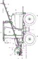
Fig. 1 is a perspective view of a self-propelled medicine applicator according to a preferred embodiment of the present invention.
Fig. 2 is a left side view of the self-propelled medicament dispenser of fig. 1.
Fig. 3 is a top view of the self-propelled medicament dispenser of fig. 1.
Fig. 4 is a front view of the self-propelled medicament dispenser of fig. 1.
Fig. 5 is a circuit diagram showing a part of a hydraulic circuit of the self-propelled medicine applicator of fig. 1.
Fig. 6 is an enlarged front main portion view of the self-propelled chemical applicator of fig. 1.
Fig. 7 is a flowchart showing the steps of control of the controller of fig. 5.
Fig. 8 is a flowchart showing a controller-based sequence of the broadcast boom raising and lowering process of fig. 7.
Fig. 9 is a timing chart showing the operation of the accumulator of fig. 5.
Fig. 10 is a front view of a self-propelled medicine spreader according to another embodiment of the present invention.
Fig. 11 is a circuit diagram showing a part of a hydraulic circuit of the self-propelled medicine applicator of fig. 10.
In the figure:
a-a traveling vehicle body, a 1-a main frame, a 2-a driver seat, a 3-a steering wheel, a 4-a front wheel, a 5-a rear wheel, a 6-an operation panel, a 7-an engine hood, B-a chemical spreading device, bn-a nozzle, B1-a spreading boom, B2-a bracket device, B20-a lifting link, B21-a lifting cylinder, B22-a mounting bracket, B23-a lifting bracket, B23-an opening and closing cylinder, B23-a single-acting roller cylinder, K-a cab, K23-a cab frame, K23-a cab, K3 23-an opening and closing door, a T-working oil tank, a U-an accumulator, a U23-a roller accumulator, P23-a first pump, P23-a second pump, U23-a switching valve, a first flow dividing valve, a second flow dividing valve, a switching valve, a.
Detailed Description
Hereinafter, preferred embodiments of the present invention will be described in detail with reference to the accompanying drawings. In the description of the embodiments, the left and right directions toward the forward direction of the machine body are referred to as the left and right directions, respectively, the forward direction is referred to as the front direction, and the backward direction is referred to as the rear direction, but the configuration of the present invention is not limited thereto.
(Overall Structure)
The overall configuration example of the self-propelled chemical applicator 1 will be specifically described.
As shown in a perspective view in fig. 1, a left side view in fig. 2, a plan view in fig. 3, and a front view in fig. 4, the self-propelled medicine broadcast device 1 is configured to include a self-propelled traveling vehicle body a, a cab K provided on the traveling vehicle body a, a medicine tank M for storing medicine, and a medicine broadcast device B having a broadcast nozzle B1 for broadcasting medicine supplied from the medicine tank M to a farm.
The traveling vehicle body a includes a main frame a1, a driver seat a2, a steering wheel a3, front wheels a4, and rear wheels a 5. The main frame a1 is formed to extend in the front-rear direction of the running vehicle body a. The driver seat a2 is suitable for a seat on which an operator sits when performing a driving operation of the passenger plant protection machine 1. An operation panel a6 is disposed at an appropriate position around the driver seat a2, and an operation switch, a push switch, and the like for controlling operations such as opening and closing of the broadcast nozzle b1 and broadcast of medicine are disposed on the operation panel a 6.
The steering wheel a3, which is provided upright in front of the driver seat a2, changes the direction of travel of the self-propelled medicine broadcast device 1 by at least steering the left front wheels a4, a4 by the turning operation of the operator. That is, the front wheels a4, a4 are at least steered wheels that are steered by a turning operation of the steering wheel a 3.
The engine ID power in the engine cover a7 is appropriately shifted in a transmission (not shown), and the front wheel a4 and the rear wheel a5 are rotationally driven by the power having been shifted.
The cab K forms a member room by surrounding the operator's seat a2 and peripheral equipment, a steering wheel, and the like. The cab K is disposed between the medicine tank M and the broadcast spray bar b 1. The cab K is constituted by a cab frame K1, a cab ceiling K2, left and right opening and closing doors K3L, K3R, and the like.
The medicine tank M is a container for storing medicine. The medicine canister M is disposed on the rear side of the cab K as shown in fig. 3 in a plan view, is formed in a コ shape so as to surround both the left and right sides and the rear side of the operator's seat a2, and is detachably mounted on the main frame a 1. The chemical stored in the chemical tank M is a liquid such as a liquid in which a fertilizer, an agricultural chemical, or the like is dissolved in a solvent (e.g., water), or a liquid (e.g., water) containing a solid component such as a fertilizer, an agricultural chemical, or the like.
(means for spreading medicine)
The chemical dispensing device B includes a dispensing nozzle B1 for dispensing to a farm, and a holder device B2 for holding the dispensing nozzle B1 on the carriage body a.
The broadcast spray lance b1 is composed of a center spray lance b1F located in front of the traveling vehicle body 2 and sub spray lances b1L and b1R located on both sides.
The center boom b1F extends horizontally in the vehicle width direction of the running vehicle body 2. Further, a plurality of nozzles bn for ejecting the medicine in the form of mist are arranged at intervals on the center nozzle bar b 1F.
The sub-booms b1L, b1R are rotatably disposed on the left and right sides of the center boom b 1F. A plurality of nozzles bn for spraying a medicine are arranged at intervals in the sub-spray bars b1L and b 1R. By the rotation of the sub booms b1L, b1R, the broadcast boom b1 can switch between a broadcast attitude in which the entire broadcast boom b1L, b1R is substantially straight and a storage attitude in which the sub booms b1L, b1R are stored in both the left and right sides of the running vehicle body 2 so as to extend in the vehicle width direction (left-right direction) of the running vehicle body a. The broadcast lance b1 configured in this way can broadcast a medicine to the front side of the self-propelled medicine broadcast machine 1 in a wide width in the right and left directions in the broadcast posture.
As shown in fig. 2 and 3, the stand device b2 is a device for supporting the broadcast spray lance b1 to the traveling vehicle body a so as to be able to ascend and descend, and is configured to include: a lift link b20 rotated by extension or contraction of the lift cylinder b 21; an installation frame b21 connected with the front end of the lifting connecting rod b 20; a lifter frame b23 mounted to the mounting frame b22 and moving up and down by the rotation of the lifter link b 20; and an opening/closing cylinder b24 for opening and closing the sub booms b1L, b1R on both sides by rotating substantially horizontally. As shown in fig. 4, the mount b22 has a rectangular frame shape in plan view, and is configured such that the lifter frame b23 is pivotally supported by a yaw axis Y provided at a lower portion so as to be rotatable about the yaw axis Y.
A center boom b1(b1F) is attached to the front portion of the lifter frame b23, and sub booms b1L and b1R are rotatably attached to the left and right sides of the lifter frame b23 so as to be extendable in the vehicle width direction. With this configuration, when the elevator frame b23 is lifted, the broadcast nozzle b1 is also lifted.
The opening/closing cylinder b24 can switch between a broadcast posture extending in the vehicle width direction of the running vehicle body a and storage postures at both left and right sides of the running vehicle body a by extending or shortening, and is connected to the lifter frame b23 and the sub booms b1L, b1R, and is configured such that when the opening/closing cylinder b24 extends or shortens, the sub booms b1L, b1R at both sides rotate. The expansion and contraction of the opening/closing cylinder b24 are controlled by a controller C described later.
(vibration damping device of broadcast sowing spray rod)
As shown in fig. 4, the lifter frame b23 is provided with an accumulator U that absorbs pressure fluctuations in the lift cylinder b 24.
Fig. 5 is a circuit diagram showing a part of the hydraulic circuit of the self-propelled chemical applicator 1.
As shown in fig. 5, the damper mechanism of the broadcast nozzle b1 includes an accumulator U, an on-off valve U1 provided in a supply/discharge passage of the hydraulic oil that communicates between the lift cylinder b21 and the accumulator U, and a controller C that controls opening and closing of the on-off valve U1.
The first to second pumps P1, P2 as hydraulic pumps are constituted by constant capacity type gear pumps driven by power of an engine. A discharge oil passage 100 through which the working oil discharged from the first to second pumps P1, P2 flows is connected to a first constant flow rate dividing valve u2 that divides a constant flow rate. The first constant flow diverter valve u2 is connected to the second constant flow diverter valve u3 via the first oil passage 101. The second fixed/divided valve u3 is connected to a discharge oil passage 100a through which discharge oil (pilot oil) discharged from the third pump P3 flows, and is connected to the vertical movement switching valve u4 through a second oil passage 102.
The up-down switching valve u4 is an electromagnetic switching valve and is switchable between an extension position u41 which is an operating position for extending the lift cylinder b21, a contraction position u42 which is an operating position for contracting the lift cylinder b21, and a stop position u43 for stopping the lift cylinder b 24.
The vertical movement switching valve u4 is connected to a third oil passage 103 communicating with the left and right lift cylinders b21 and the on-off valve u1, and a discharge oil passage 104 returning the hydraulic oil to the hydraulic oil tank T, in addition to the second oil passage 102. A relief valve u5 is provided between the second oil passage 102 and the discharge oil passage 104, and opens when the hydraulic pressure in the second oil passage 102 exceeds a set value, thereby draining the hydraulic pressure to the discharge oil passage 104.
When the up-down movement switching valve u4 is switched to the extended position u41, the second oil passage 102 and the third oil passage 103 communicate with each other, and the hydraulic oil discharged from the first to second pumps P1 and P2 flows into the piston side chamber b211 of the lift cylinder b21 through the discharge oil passage 100, the first oil passage 101, the second oil passage 102, and the third oil passage 103. Accordingly, the lift cylinder b21 extends, and accordingly, the lift link b20 rotates upward, the lift frame b23 moves upward, and the broadcast nozzle b1 rises together with the lift frame relative to the traveling vehicle body 2.
When the up-down movement switching valve u4 is switched to the contraction position u42, the discharge oil passage 104 and the third oil passage 103 communicate. Accordingly, the hydraulic oil in the piston side chamber b211 of the lift cylinder b21 passes through the third oil passage 103 and the discharge oil passage 104 and returns to the hydraulic oil tank T. Accordingly, the lift cylinder b21 contracts, and therefore the lift link b20 rotates downward, the lift frame b23 moves downward, and the broadcast nozzle b1 descends together with the lift frame b23 with respect to the running vehicle body a.
When the up-down movement switching valve u4 is switched to the stop position u43, the third oil passage 103 is blocked. Thereby, the hydraulic oil that has passed through the third oil passage 103 and entered and exited the piston side chamber b211 is cut off, and the height of the spray lance b1 with respect to the running vehicle body a is maintained.
The opening/closing valve U1 is an electromagnetic switching valve that can switch between a communication position U11 at which the piston side chamber b211 of the lift cylinder b21 communicates with the accumulator U and a blocking position U12 at which communication is blocked.
When the opening and closing valve U1 is switched to the communication position U11 (open control of the opening and closing valve U1), the third oil passage 103 and the accumulator U communicate, whereby the piston-side chamber b211 of the lift cylinder b21 and the accumulator U communicate. Accordingly, the hydraulic oil flows in and out of the accumulator U, and the accumulator U absorbs pressure fluctuations in the lift cylinder b21 and exerts a spring action, so that vibration of the broadcast spray lance b1 is suppressed and a vibration damping function is exerted.
When the opening/closing valve U1 is switched to the blocking position U12 (closing control of the opening/closing valve U1), the communication between the third oil passage 103 and the accumulator U is blocked, and the communication between the piston side chamber b211 of the lift cylinder b21 and the accumulator U is thereby blocked. This stops the vibration damping function of the accumulator U, and improves the response when the broadcast nozzle b1 is raised and lowered. In detail, the responsiveness is rapidity from when the boom up switch or the boom down switch is operated to when the boom up switch or the boom down switch starts the up-down operation of the broadcast boom b 1.
The controller C is a control device that can control the vertical movement switching valve u4 and the opening/closing valve u1, and includes a CPU, a ROM, a RAM, and the like, and stores a predetermined control program. The vertical movement switching valve u4 and the opening/closing valve u1 are electrically connected to the controller C, and are controlled by the controller C to be switchable between states. The controller C may be configured to control the states of the vertical movement switching valve u4 and the opening/closing valve u1 by using a timer, a relay, or the like, without using a CPU, a ROM, a RAM, or the like.
The controller C is electrically connected to the operation panel a6, and can acquire operations of various operation switches provided on the operation panel a6 as signals. That is, the operation information of the operator on the operation panel a6 can be acquired. The operation panel a6 is provided with at least a boom raising switch, not shown, which is operated when raising the broadcast boom b1 with respect to the traveling vehicle body a, a boom lowering switch, which is operated when lowering the broadcast boom b1 with respect to the traveling vehicle body a, and a push switch, which is operated when power is supplied to the self-propelled medicine broadcast device 1. The push switch is an operation switch that can be switched on and off, and the condition for operating the engine of the self-propelled chemical applicator 1 is set when the push switch is off. Therefore, the operator can operate the engine of the self-propelled chemical applicator 1 by a predetermined operation after turning on the key switch. The controller C executes control described later based on a signal from the operation panel a6, and switches the states of the up-down switching valve u4 and the opening/closing valve u 1. Further, a timer C1 as a timer unit and a relay C2 for detecting an operation of a key switch to switch contacts in a circuit are connected to the controller C.
Fig. 6 is an enlarged front view of the self-propelled chemical applicator 1.
As shown in fig. 6, the accumulator U is disposed at the substantially right and left center of the lifter frame b23 in front of the cab K and is located on the substantially center line in the vehicle width direction of the running vehicle body 2. Thus, the accumulator U disposed substantially at the center of the traveling vehicle body a is marked as a center, and the operator can easily perform the linear travel operation of the self-propelled chemical applicator 1. In addition, the fault of the accumulator U is easy to be visually confirmed, and the maintainability is improved.
The opening/closing valve U1 is housed in a case X1 disposed below the accumulator U shown in fig. 6, and the vertical movement switching valve U4 is housed in a case X2 disposed near the side of the case X1. The accumulator U may be detachably mounted to the case X1. As shown in fig. 6, the casing X1 and the casing X2 are fixed to the lifter frame b23 in close proximity, and the on-off valve u1 and the vertical switching valve u4 are disposed in close proximity. Further, the case X1 and the case X2 may be constituted by one case, and the on-off valve u1 and the vertical movement switching valve u4 may be accommodated in the one case. With the above-described structure in which the opening/closing valve u1 and the vertical movement switching valve u4 are directly and integrally attached, the ease of assembly can be improved, the number of assembly steps can be reduced, and the installation space can be made compact.
The accumulator U, the case X1, and the case X2 are provided at the front of the body of the traveling vehicle body 2. Specifically, the structure is provided at the forefront of the machine body. This facilitates maintenance. The broadcast nozzle b1 to which the nozzle bn is attached is configured to be able to be raised and lowered to an arbitrary position by raising and lowering the lift frame b 23. The accumulator U, the casing X1, and the casing X2 are attached to the elevator frame b 23.
Accordingly, the accumulator U, the casing X1, and the casing X2 can be lifted and lowered to an arbitrary position while maintaining their positional relationships, and therefore, the maintenance is facilitated without affecting the piping.
(opening/closing control of opening/closing valve)
Fig. 7 is a flowchart showing the steps of control by the controller C.
The controller C controls the opening/closing valve u1 and the up-down switching valve u4 in the order shown in the flowchart of fig. 7. Further, as an initial condition, the key switch is turned off, and the opening/closing valve u1 is switched to the cutoff position u 12.
When the controller C receives a signal indicating that the push switch has been turned on (step S101), it controls the on-off valve u1 to be switched to the communication position u11 (step S102). This exerts the vibration damping function of the accumulator U, and suppresses the vibration of the broadcast lance b 1. Therefore, according to the configuration in which the opening/closing valve u1 is opened in conjunction with the on operation of the key switch by the operator, the opening/closing valve u1 is reliably opened only by the power supply being turned on when the engine is stopped, when the engine is in operation, or during operation. This eliminates the need for the operator to manually open the opening/closing valve u1, which is a conventional procedure, and improves convenience. Further, there is no operation in which the operator forgets to open the opening/closing valve u1 by manual operation during the work. Further, a switch for turning on the opening/closing valve u1 is not necessary.
Then, when the controller C receives a signal indicating that the boom up switch has been turned on or that the boom down switch has been turned on (step S103), the controller C performs a process of raising and lowering the broadcast boom b1 (step S104), which will be described later.
After the on-off valve u1 is switched to the communication position u11 in step S102, the controller C acquires a signal indicating that the push switch is turned off (step S105), and then switches the on-off valve u1 to the cutoff position u12 (step S106). As a result, the vibration damping function of the accumulator U is stopped in conjunction with the key switch being turned off. Thus, the vibration damping function of the accumulator U is automatically turned off at the non-operation time, and the broadcast spray bar b1 is fixed to the traveling vehicle body a, and with this configuration, for example, at the non-operation time such as when the self-propelled medicine broadcast device 1 is transported, the problem that the broadcast spray bar b1 swings up and down and contacts an external obstacle can be prevented. Further, when the accumulator U is removed for maintenance, the on-off valve U1 is switched to the blocking position U12, so that dust and the like can be prevented from entering the hydraulic circuit.
Fig. 8 is a flowchart showing a sequence of the broadcast boom raising and lowering process (step S104) of fig. 7 by the controller C. When a signal indicating that the boom up switch is turned on or the boom down switch is turned on is obtained in step S103, the controller C switches the up/down switching valve u4 to the extended position u41 to raise the broadcast boom b1 when a signal indicating that the boom up switch is turned on is obtained. When a signal indicating that the boom lowering switch has been turned on is received, the up-down switching valve u4 is switched to the retracted position u42, and the broadcast boom b1 is lowered (step S201).
At the same time, the opening and closing valve u1 is immediately switched to the cutoff position u12 (step S202). This can improve the response of the subsequent raising and lowering of the broadcast nozzle b 1.
Here, the controller C starts the timer C1 to count the set time t at the same time as the start of the raising and lowering of the broadcast nozzle b1 (step S203). The set time t is set to a predetermined short time, for example, about 1 second.
Then, the controller C switches the opening-closing valve u1 to the communication position u11 when the set time t elapses (step S204). That is, the controller C switches the on-off valve u1 to the cutoff position u12 immediately only in a short time immediately after the start of the raising and lowering operation of the broadcast nozzle b1, and switches the on-off valve u1 to the communication position u11 during the raising and lowering operation of the broadcast nozzle b1 after the start of the raising and lowering operation. This ensures quick response during the raising and lowering operation of the broadcast nozzle b1, and also reduces vibration of the broadcast nozzle b1 by exerting the vibration damping function of the accumulator U during the raising and lowering operation of the broadcast nozzle b1 after the next raising and lowering operation is started. As a result, the operation of the broadcast lance b1 can be stabilized, and safety can be improved. That is, according to the structure in which the opening control of the opening/closing valve U1 is performed after the completion of the lifting operation of the broadcast nozzle b1, as in the conventional case, when the opening/closing valve U1 is opened, the working oil rapidly flows from the lift cylinder b21 to the accumulator U side due to the pressure difference between the lift cylinder b21 and the working oil of the accumulator U, and as a result, the lift cylinder b21 expands or contracts and the broadcast nozzle b1 descends from the stop position, which causes a problem of unstable operation, but by performing the opening control of the opening/closing valve U1 during the lifting operation of the broadcast nozzle b1, the pressure difference between the lift cylinder b21 and the working oil of the accumulator U can be eliminated, and the stable operation of the broadcast nozzle b1 can be realized. Here, the set time t is preferably set to be within 0.5 to 3 seconds, and more preferably within 0.5 to 1 second.
Next, when the controller C receives a signal that the boom up switch or the boom down switch is turned off (step S205), the controller C controls the up-down switching valve u4 to be switched to the stop position u43 (step S206). Thereby, the raising and lowering of the broadcast nozzle b1 is stopped, and the process of raising and lowering the broadcast nozzle b1 of fig. 7 is completed (step S104).
Although not shown in fig. 7 and 8, when the boom up switch or the boom down switch is continuously operated for a predetermined time (about 0.5 to 1 second), the opening/closing valve u1 is manually closed without raising/lowering the broadcast boom b 1. In this case, other switches and levers may be provided instead of the boom up switch and boom down switch. Thus, the operation of the accumulator U can be easily stopped by the judgment of the operator in a situation where the accumulator U is not required to be operated (for example, a situation where irregularities on the road surface are small). Further, in the case of operating the accumulator U again, the boom up switch or the boom down switch is continuously operated for a predetermined time (about 0.5 seconds to about 1 second). Thus, a switch for turning on or off the opening/closing valve u1 is not required.
Further, a vibration sensor may be provided in the machine body, and when the vibration of the machine body reaches a value within a predetermined range and continues for a predetermined time or more, the on-off valve U1 may be automatically closed to stop the operation of the accumulator U. However, the accumulator is configured to be operated by automatically opening the on-off valve u1 at least when the vibration value equal to or greater than the predetermined value continues several times.
Further, the boom up switch and the boom down switch are provided at positions operable in a state of being seated on the operator's seat a2 in the cab K, but may be configured to be provided outside the cab K. As shown in fig. 2, the sub-boom b1L passes through the side of the opening/closing door k3L, and therefore can be lowered and raised below the sub-boom b1L during raising and lowering, but the sub-boom b1L is raised and lowered during raising and lowering, which makes it easier to raise and lower. Therefore, the sub-boom b1L can be raised and lowered by operating a boom raising switch or a boom lowering switch provided outside the cab K.
The sub-booms b1L, b1R are configured to be independently movable up and down with respect to the lift frame b23, and are configured to be movable up and down by an electric hydraulic cylinder ES independent of the hydraulic circuit of fig. 5. In this case, even when the hydraulic pressure is not operated due to the engine stop, the sub-booms b1L and b1R can be raised and lowered by driving the electric hydraulic cylinder ES using the power supply of the battery by operating the boom raising switch and the boom lowering switch outside the cab K. This facilitates the movement up and down into the cab K.
Fig. 9 is a timing chart showing the operation of the accumulator U of fig. 5. In fig. 9, the on-off valve U1 is in the communication position U11 when the accumulator U is on, and is in the cutoff position U12 when the accumulator U is off. As shown in fig. 9, normally, the accumulator U is normally turned on when the push switch is turned on, but after the boom up switch is turned on or the boom down switch is turned on, the accumulator U is turned off for a set time t. As described above, the set time t is set to a short time (for example, about 1 second), but can be adjusted within a predetermined range (for example, about 0.5 to 3 seconds) by operating the operation panel a6 in order to achieve the responsiveness of raising and lowering the broadcast nozzle b1 in accordance with the weight of the broadcast nozzle b1 and the needs of the operator.
The present invention is not limited to the above embodiments, and various modifications can be made within the scope of the invention described in the claims, and it goes without saying that they also fall within the scope of the invention.
For example, in the above embodiment, as shown in fig. 4, the lift frame b23 is pivotally supported rotatably about the yaw axis Y by the yaw axis Y provided at the lower portion of the mount bracket b22, but as shown in fig. 10, the single-acting roller cylinder b25 may be disposed on one of the left and right end sides of the lift frame b23, the damper b26 may be disposed on the other of the left and right end sides, and the yaw control may be performed on the lift frame b23 by extending or shortening the single-acting roller cylinder b 25. At this time, the return operation of the single-acting roller cylinder b25 is performed by the damper b26 disposed on the other end side of the left and right sides, whereby the yaw vibration in the yaw direction of the elevator frame can be suppressed as compared with the case of using an elastic body such as a compression spring, and stable yaw control can be performed.
Fig. 11 is a circuit diagram showing a part of a hydraulic circuit of a self-propelled medicine applicator 1 according to another embodiment. In the hydraulic circuit of the self-propelled medicine broadcasting device 1 according to the other embodiment, in addition to the configuration of the hydraulic circuit shown in fig. 5, the fourth oil passage 105 is connected to the first constant pressure bypass valve u2, the single-acting roller cylinder switching valve u5 as an electromagnetic switching valve is connected to the fourth oil passage 105, and the single-acting roller cylinder switching valve u5 is switchable to an extension position u51 as an operating position for extending the single-acting roller cylinder b25, a contraction position u52 as an operating position for contracting the single-acting roller cylinder b25, and a stop position u53 for stopping the single-acting roller cylinder b 25. The lifter frame b23 is pivotally supported so as to be rotatable about the yaw axis Y, and is configured to damp the yaw direction of the lifter frame b23 by the accumulator U2.
As shown in fig. 11, the single-acting roller cylinder switching valve U5 is connected to the fifth oil passage 106, the fifth oil passage 106 is connected to the second opening/closing valve U7, and the second opening/closing valve U7 can switch between a communication position U71 at which the piston-side chamber b251 of the single-acting roller cylinder b25 and the roller accumulator U2 communicate with each other and a blocking position U72 at which the communication is blocked. The controller C controls the on/off valve u7 to be switched to the communication position u71 when a signal indicating that the key switch is turned on is received. This allows the damper function of the accumulator U2 to be exhibited, and the vibration in the yaw direction of the lift frame b23 to be suppressed. Further, when the accumulator U2 is removed for maintenance, the on-off valve U7 is switched to the cutoff position U72, and therefore, dust and the like can be prevented from entering the hydraulic circuit.
The single-acting roller cylinder switching valve u5 is connected to the second discharge oil passage 107 for returning the hydraulic oil to the hydraulic oil tank T, and a relief valve u6 is provided between the fourth oil passage 105 and the second discharge oil passage 107. Further, although not shown, the single-acting roller cylinder switching valve u5 and the second opening/closing valve u7 are connected to the controller C, and the state can be controlled by the controller C. Further, the cylinder switching valve u5 for single-acting roller and the second opening/closing valve u7 are housed in a casing X3 shown in fig. 10.
Here, the accumulator U, U2 may be disposed on either the left or right side with respect to the center line in the traveling direction of the machine body, and the hydraulic valve may be disposed on the other side, in a plan view of the machine body. In this way, the accumulator and the hydraulic valve, which are heavy in weight, are disposed on the left and right sides with respect to the center line in the traveling direction of the machine body, so that the left and right balance of the machine body can be improved.
Further, the on-off valve to the accumulator U, U2 may be opened, and a display lamp for notifying the operable state of the accumulator U, U2 may be provided near the push switch or around the handle of the operation unit. This allows the operator to easily check the operating state of the accumulator U, U2 while the vehicle is stopped or traveling (working or moving). Such a configuration is effective particularly in the case where there is no on switch for operating the accumulator U, U2 (a configuration in which the operation of the accumulator U, U2 is automatically performed in conjunction with the on operation of the key switch).
Claims (4)
1. A self-propelled chemical broadcast sowing machine is provided with:
a traveling vehicle body (A) that travels the machine body;
an operation unit (a6) that receives an operation by an operator;
a medicine dispensing section (b1) configured to be able to be lifted and lowered by extension and contraction of a lift cylinder (b 21);
an accumulator (U) which is connected to the lift cylinder (b21) and stores the pressurized working fluid;
an on-off valve (U1) that opens and closes a passage that communicates the lift cylinder (b21) and the accumulator (U); and
a control unit (C) configured to be able to acquire operation information of the operation unit (a6) and to control the extension or contraction of the lift cylinder (b21) and the opening/closing of the on-off valve (u1),
the self-propelled chemical broadcast sowing machine is characterized in that,
the operation part (a6) is provided with a key switch for connecting the power supply of the self-propelled medicine spreader,
in the case of the control unit (C),
the opening/closing valve (u1) is controlled to be opened under the condition that the push switch is operated to turn on the power of the self-propelled chemical applicator,
the open/close valve (u1) is closed under the condition that the power supply of the self-propelled chemical applicator is cut off by the operation of the push switch.
2. The self-propelled pharmaceutical spreader of claim 1,
the control unit (C) is configured to perform opening control after closing control of the opening/closing valve (u1) for a predetermined set time (t) when the operation unit (a6) performs an operation of extending or shortening the lift cylinder (b 21).
3. The self-propelled pharmaceutical spreader of claim 2,
the set time (t) is in the range of 0.5 seconds to 1 second.
4. The self-propelled pharmaceutical spreader of claim 2,
the set time (t) can be adjusted by the operation of the operation unit (a 6).
Applications Claiming Priority (2)
| Application Number | Priority Date | Filing Date | Title |
|---|---|---|---|
| JP2019-141750 | 2019-07-31 | ||
| JP2019141750A JP7221165B2 (en) | 2019-07-31 | 2019-07-31 | Self-propelled chemical sprayer |
Publications (1)
| Publication Number | Publication Date |
|---|---|
| CN112293383A true CN112293383A (en) | 2021-02-02 |
Family
ID=74483212
Family Applications (1)
| Application Number | Title | Priority Date | Filing Date |
|---|---|---|---|
| CN202010761680.4A Pending CN112293383A (en) | 2019-07-31 | 2020-07-31 | Self-propelled medicament broadcast seeder |
Country Status (3)
| Country | Link |
|---|---|
| JP (1) | JP7221165B2 (en) |
| KR (1) | KR20210015666A (en) |
| CN (1) | CN112293383A (en) |
Cited By (1)
| Publication number | Priority date | Publication date | Assignee | Title |
|---|---|---|---|---|
| CN112438242A (en) * | 2019-08-29 | 2021-03-05 | 井关农机株式会社 | Self-propelled plant protection machinery |
Families Citing this family (2)
| Publication number | Priority date | Publication date | Assignee | Title |
|---|---|---|---|---|
| DE102018107135A1 (en) | 2018-03-26 | 2019-09-26 | Aixtron Se | Provided with an individual identifier component of a CVD device and method for transmitting information |
| KR102484410B1 (en) * | 2020-07-07 | 2023-01-03 | 주식회사 한아 | Pest control apparatus for multi-direction with a automatic switching function |
Family Cites Families (9)
| Publication number | Priority date | Publication date | Assignee | Title |
|---|---|---|---|---|
| JPS62163610A (en) * | 1986-01-14 | 1987-07-20 | 株式会社クボタ | Rising and falling operation structure of earth working apparatus of working vehicle |
| DE102007047886A1 (en) * | 2007-11-28 | 2009-06-04 | John Deere Fabriek Horst B.V. | spray boom |
| JP5801618B2 (en) | 2011-06-21 | 2015-10-28 | カヤバ工業株式会社 | Boom sprayer and boom damping device |
| JP6220697B2 (en) * | 2014-02-19 | 2017-10-25 | Kyb株式会社 | Spraying device and boom damping device |
| US10280948B2 (en) * | 2014-04-04 | 2019-05-07 | Volvo Construction Equipment Ab | Hydraulic system and method for controlling an implement of a working machine |
| JP6514594B2 (en) * | 2015-07-21 | 2019-05-15 | Kyb株式会社 | Boom lifting device and boom sprayer |
| JP2017131179A (en) * | 2016-01-29 | 2017-08-03 | Kyb株式会社 | Boom displacement device and boom sprayer |
| JP6637369B2 (en) * | 2016-04-08 | 2020-01-29 | Kyb株式会社 | Boom damper and boom sprayer |
| JP2019017310A (en) | 2017-07-18 | 2019-02-07 | 井関農機株式会社 | Self-travel type pest control machine |
-
2019
- 2019-07-31 JP JP2019141750A patent/JP7221165B2/en active Active
-
2020
- 2020-07-24 KR KR1020200092059A patent/KR20210015666A/en active Search and Examination
- 2020-07-31 CN CN202010761680.4A patent/CN112293383A/en active Pending
Cited By (1)
| Publication number | Priority date | Publication date | Assignee | Title |
|---|---|---|---|---|
| CN112438242A (en) * | 2019-08-29 | 2021-03-05 | 井关农机株式会社 | Self-propelled plant protection machinery |
Also Published As
| Publication number | Publication date |
|---|---|
| KR20210015666A (en) | 2021-02-10 |
| JP7221165B2 (en) | 2023-02-13 |
| JP2021023160A (en) | 2021-02-22 |
Similar Documents
| Publication | Publication Date | Title |
|---|---|---|
| CN112293383A (en) | Self-propelled medicament broadcast seeder | |
| JP7192729B2 (en) | chemical sprayer | |
| JP4143861B2 (en) | Drug spraying work vehicle | |
| JP2003009750A (en) | Chemical spraying work vehicle | |
| JP7322942B2 (en) | Self-propelled chemical sprayer | |
| JP2020150914A (en) | Sulky management machine | |
| JP2023133388A5 (en) | ||
| JP4259207B2 (en) | Scatter boom storage device for spray vehicle | |
| JP6079690B2 (en) | Chemical spraying work vehicle | |
| JP5783069B2 (en) | Multipurpose farm vehicle | |
| JP2000078945A (en) | Riding self-propelled spray device | |
| JP4655549B2 (en) | Scatter work vehicle | |
| JP5560762B2 (en) | Work vehicle | |
| JP5255863B2 (en) | Sprinkler | |
| JP2014226094A (en) | Working vehicle | |
| JP2020202803A (en) | Riding management machine | |
| JP2012029654A (en) | Chemical sprayer implement | |
| JP4192474B2 (en) | Tractor | |
| JP2002331261A (en) | Liquid sprayer | |
| JP2005138043A (en) | Liquid chemical spraying work vehicle | |
| KR102305669B1 (en) | Tilting device of fan blower for pest control machine | |
| JP2011250697A (en) | Working vehicle | |
| JP3971494B2 (en) | Cabin control vehicle with cabin | |
| JP2008295343A (en) | Herbicide applying machine | |
| JP2002034422A (en) | Horizontal controller of chemical spray device |
Legal Events
| Date | Code | Title | Description |
|---|---|---|---|
| PB01 | Publication | ||
| PB01 | Publication | ||
| SE01 | Entry into force of request for substantive examination | ||
| SE01 | Entry into force of request for substantive examination |