KR20210015666A - Self-propelled medication spreader - Google Patents
Self-propelled medication spreader Download PDFInfo
- Publication number
- KR20210015666A KR20210015666A KR1020200092059A KR20200092059A KR20210015666A KR 20210015666 A KR20210015666 A KR 20210015666A KR 1020200092059 A KR1020200092059 A KR 1020200092059A KR 20200092059 A KR20200092059 A KR 20200092059A KR 20210015666 A KR20210015666 A KR 20210015666A
- Authority
- KR
- South Korea
- Prior art keywords
- valve
- self
- boom
- accumulator
- propelled
- Prior art date
Links
Images


Classifications
-
- A—HUMAN NECESSITIES
- A01—AGRICULTURE; FORESTRY; ANIMAL HUSBANDRY; HUNTING; TRAPPING; FISHING
- A01M—CATCHING, TRAPPING OR SCARING OF ANIMALS; APPARATUS FOR THE DESTRUCTION OF NOXIOUS ANIMALS OR NOXIOUS PLANTS
- A01M7/00—Special adaptations or arrangements of liquid-spraying apparatus for purposes covered by this subclass
- A01M7/0003—Atomisers or mist blowers
- A01M7/0014—Field atomisers, e.g. orchard atomisers, self-propelled, drawn or tractor-mounted
-
- A—HUMAN NECESSITIES
- A01—AGRICULTURE; FORESTRY; ANIMAL HUSBANDRY; HUNTING; TRAPPING; FISHING
- A01M—CATCHING, TRAPPING OR SCARING OF ANIMALS; APPARATUS FOR THE DESTRUCTION OF NOXIOUS ANIMALS OR NOXIOUS PLANTS
- A01M7/00—Special adaptations or arrangements of liquid-spraying apparatus for purposes covered by this subclass
- A01M7/0025—Mechanical sprayers
- A01M7/0032—Pressure sprayers
- A01M7/0042—Field sprayers, e.g. self-propelled, drawn or tractor-mounted
-
- A—HUMAN NECESSITIES
- A01—AGRICULTURE; FORESTRY; ANIMAL HUSBANDRY; HUNTING; TRAPPING; FISHING
- A01M—CATCHING, TRAPPING OR SCARING OF ANIMALS; APPARATUS FOR THE DESTRUCTION OF NOXIOUS ANIMALS OR NOXIOUS PLANTS
- A01M7/00—Special adaptations or arrangements of liquid-spraying apparatus for purposes covered by this subclass
- A01M7/005—Special arrangements or adaptations of the spraying or distributing parts, e.g. adaptations or mounting of the spray booms, mounting of the nozzles, protection shields
-
- A—HUMAN NECESSITIES
- A01—AGRICULTURE; FORESTRY; ANIMAL HUSBANDRY; HUNTING; TRAPPING; FISHING
- A01M—CATCHING, TRAPPING OR SCARING OF ANIMALS; APPARATUS FOR THE DESTRUCTION OF NOXIOUS ANIMALS OR NOXIOUS PLANTS
- A01M7/00—Special adaptations or arrangements of liquid-spraying apparatus for purposes covered by this subclass
- A01M7/0082—Undercarriages, frames, mountings, couplings, tanks
-
- A—HUMAN NECESSITIES
- A01—AGRICULTURE; FORESTRY; ANIMAL HUSBANDRY; HUNTING; TRAPPING; FISHING
- A01M—CATCHING, TRAPPING OR SCARING OF ANIMALS; APPARATUS FOR THE DESTRUCTION OF NOXIOUS ANIMALS OR NOXIOUS PLANTS
- A01M7/00—Special adaptations or arrangements of liquid-spraying apparatus for purposes covered by this subclass
- A01M7/0089—Regulating or controlling systems
-
- A—HUMAN NECESSITIES
- A01—AGRICULTURE; FORESTRY; ANIMAL HUSBANDRY; HUNTING; TRAPPING; FISHING
- A01M—CATCHING, TRAPPING OR SCARING OF ANIMALS; APPARATUS FOR THE DESTRUCTION OF NOXIOUS ANIMALS OR NOXIOUS PLANTS
- A01M2200/00—Kind of animal
- A01M2200/01—Insects
-
- Y—GENERAL TAGGING OF NEW TECHNOLOGICAL DEVELOPMENTS; GENERAL TAGGING OF CROSS-SECTIONAL TECHNOLOGIES SPANNING OVER SEVERAL SECTIONS OF THE IPC; TECHNICAL SUBJECTS COVERED BY FORMER USPC CROSS-REFERENCE ART COLLECTIONS [XRACs] AND DIGESTS
- Y10—TECHNICAL SUBJECTS COVERED BY FORMER USPC
- Y10S—TECHNICAL SUBJECTS COVERED BY FORMER USPC CROSS-REFERENCE ART COLLECTIONS [XRACs] AND DIGESTS
- Y10S43/00—Fishing, trapping, and vermin destroying
Landscapes
- Life Sciences & Earth Sciences (AREA)
- Engineering & Computer Science (AREA)
- Insects & Arthropods (AREA)
- Pest Control & Pesticides (AREA)
- Wood Science & Technology (AREA)
- Zoology (AREA)
- Environmental Sciences (AREA)
- Mechanical Engineering (AREA)
- Catching Or Destruction (AREA)
Abstract
Description
본 발명은 약제의 산포를 행하는 자주식 약제 산포기에 관한 것이다.The present invention relates to a self-propelled drug spreader for dispersing drugs.
종래, 방제액 등의 약제를 분무 산포하는 산포 붐을 구비한 약제 산포 장치를 주행 차체 전방부에 탑재한 자주식 약제 산포기가 알려져 있다.BACKGROUND ART Conventionally, a self-propelled medicament dispersing machine is known in which a drug dispersing device having a dispersing boom for spraying and dispersing drugs such as a control solution is mounted on the front of a traveling vehicle.
예를 들면, 특허문헌 1에는 승강 실린더의 신장 또는 단축에 의해 상하 이동하는 승강 링크에 승강 프레임이 설치되고, 이 승강 프레임에 산포 붐이 장착된 자주식 약제 산포기 개시되어 있다.For example, Patent Document 1 discloses a self-propelled drug dispersing machine in which an elevating frame is provided on an elevating link that moves up and down by elongation or shortening of an elevating cylinder, and a scattering boom is attached to the elevating frame.
여기에서 산포 붐은 주행 차체에 대해서 일단이 지지되고, 타단이 자유단이 되도록 편측 지지되어 있기 때문에 작업 시에 포장의 요철에 의해 주행 차체가 진동하면 그 진동이 산포 붐에 전달되어 격렬하게 진동해버린다. 그 결과, 약제의 산포에 불균일이 발생하여 작업 능률 및 약제 산포 효율의 저하를 초래하게 되기 때문에 산포 붐의 진동을 억지하는 것은 종래로부터의 과제이었다.Here, the scatter boom is supported on one side so that one end is supported with respect to the traveling vehicle body and the other end becomes a free end, so if the traveling vehicle body vibrates due to irregularities in the pavement during work, the vibration is transmitted to the scatter boom and vibrates violently. Discard it. As a result, it has been a conventional problem to suppress the vibration of the dispersing boom because unevenness occurs in the dispersing of the drug, leading to a decrease in work efficiency and drug dispersing efficiency.
그래서 특허문헌 2에는 승강 실린더에 승강 실린더 내의 압력 변동을 흡수하는 어큐뮬레이터를 연결함으로써 어큐뮬레이터에 의해 승강 실린더에 스프링 작용을 발휘시키고, 이에 따라 승강 프레임의 진동을 저감함으로써 작업 시에 있어서의 산포 붐의 진동를 억제하는 기술이 개시되어 있다. 또한, 특허문헌 3에는 승강 실린더와 어큐뮬레이터의 작동유의 급배 통로에 개폐 밸브를 설치하고, 승강 프레임의 상하 이동 시에 있어서는 개폐 밸브를 폐쇄하여 승강 실린더와 어큐뮬레이터의 작동유의 급배를 일시적으로 차단하고, 이것에 의해 산포 붐의 승강 조작에 대한 응답성을 향상하는 기술이 개시되어 있다.Therefore, in Patent Document 2, by connecting an accumulator that absorbs pressure fluctuations in the lifting cylinder to the lifting cylinder, a spring action is exerted on the lifting cylinder by the accumulator, thereby reducing the vibration of the lifting frame, thereby reducing the vibration of the scattering boom during work. A technique for suppressing is disclosed. In addition, in Patent Document 3, an on-off valve is provided in the supply/discharge passage of the hydraulic oil of the lifting cylinder and the accumulator, and when the lifting frame is moved up and down, the opening/closing valve is closed to temporarily cut off the supply and discharge of hydraulic oil to the lifting cylinder and the accumulator. As a result, a technique for improving the responsiveness to the lifting operation of the scattering boom is disclosed.
여기에서 특허문헌 2 및 특허문헌 3에 개시된 선행 기술을 적용한 자주식 약제 산포기에 의하면 어큐뮬레이터가 승강 실린더 내의 압력 변동을 흡수해서 스프링 작용을 발휘할 때 자주식 약제 산포기의 주행 차체에 대하여 산포 붐은 고정되지 않고 상하로 요동 가능하게 되어 있다.Here, according to the self-propelled drug spreader to which the prior art disclosed in Patent Document 2 and Patent Document 3 is applied, when the accumulator absorbs pressure fluctuations in the lifting cylinder and exerts a spring action, the dispersion boom is not fixed with respect to the traveling body of the self-propelled drug spreader. It is made to be able to swing up and down without doing it.
그러나 비작업 시에 있어서는 어큐뮬레이터에 의한 스프링 작용을 오프로 하고, 주행 차체에 대하여 산포 붐을 고정하는 것이 바람직한 경우도 있다. 예를 들면, 자주식 약제 산포기를 수송할 때 등 산포 붐이 상하로 요동 가능하게 되어 있으면 회전에 의해 외부의 장해물에 접촉할 우려가 있다. 따라서, 이러한 경우에 있어서는 종래 작업자가 승강 실린더와 어큐뮬레이터의 작동유의 급배 통로에 설치된 개폐 밸브를 수동으로 폐쇄 조작할 필요가 있으며, 불편했다. 또한, 개폐 밸브를 폐쇄 조작한 후 작업 시에 다시 개방 조작하는 것을 작업자가 실념할 우려도 존재했다.However, in some cases, it is desirable to turn off the spring action by the accumulator during non-working and to fix the spreading boom to the traveling vehicle body. For example, when a self-propelled drug spreader is transported or the like, if the spreading boom is able to swing up and down, there is a fear of contacting an external obstacle by rotation. Therefore, in this case, it is necessary for a conventional operator to manually close the on/off valve provided in the hydraulic oil supply/discharge passage of the lifting cylinder and the accumulator, which is inconvenient. In addition, there was also a concern that the operator would be discouraged from closing the on/off valve and then opening it again during work.
또한, 산포 붐의 승강 동작 중에 있어서 승강 실린더와 어큐뮬레이터의 작동유의 급배 통로에 설치된 개폐 밸브를 폐쇄하고, 산포 붐의 승강 동작이 완료되어 정지한 후 개폐 밸브를 개방하는 구성에 의하면 개폐 밸브를 개방했을 때에 승강 실린더와 어큐뮬레이터의 작동유의 압력차에 의해 승강 실린더로부터 어큐뮬레이터측으로 급속하게 작동유가 흘러 들어오고, 그 결과 승강 실린더가 급속하게 단축되어 산포 붐이 정지 위치보다 하강해서 동작이 불안정해지는 문제가 있었다.In addition, according to the configuration of closing the on/off valve installed in the supply/discharge passage of the hydraulic oil of the lifting cylinder and the accumulator during the raising and lowering of the dispersion boom, and opening the opening/closing valve after the raising and lowering of the dispersion boom is completed and stopped, At this time, hydraulic oil rapidly flows from the lifting cylinder to the accumulator side due to a pressure difference between the lifting cylinder and the accumulator, and as a result, the lifting cylinder rapidly shortens, causing the scatter boom to descend from the stop position, resulting in a problem that the operation becomes unstable.
이렇게 종래의 자주식 약제 산포기는 어큐뮬레이터를 이용한 산포 붐의 제진 기능에 있어서 편리성이나 안정성의 면에서 개량의 여지가 존재했다. 그래서 본 발명은 어큐뮬레이터를 이용한 산포 붐의 제진 기능의 편리성이나 안전성을 향상하도록 한 자주식 약제 산포기를 제공함으로써 이러한 종래의 문제점을 해소하는 것을 목적으로 한다.As such, the conventional self-propelled drug spreader has room for improvement in terms of convenience and stability in the vibration suppression function of the dispersion boom using an accumulator. Accordingly, an object of the present invention is to solve such a conventional problem by providing a self-propelled drug spreader that improves the convenience and safety of the vibration suppression function of the dispersion boom using an accumulator.
상기 목적을 달성하기 위해서 청구항 1의 발명은 기체를 주행시키는 주행 차체(A)와, 작업자의 조작을 받아들이는 조작부(a6)와, 승강 실린더(b21)의 신장 또는 단축에 의해 승강 가능하게 구성된 약제 산포부(b1)와, 승강 실린더(b21)와 접속되어 가압된 작동 유체를 저장하는 어큐뮬레이터(U)와, 승강 실린더(b21)와 어큐뮬레이터(U)를 연통하는 통로를 개폐하는 개폐 밸브(u1)와, 조작부(a6)의 조작 정보를 취득 가능하게 구성되고, 승강 실린더(b21)의 신장 또는 단축 및 개폐 밸브(u1)의 개폐를 제어 가능하게 구성된 제어부(C)를 구비하는 자주식 약제 산포기이며, 조작부(a6)는 자주식 약제 산포기의 전원을 온하는 키 스위치를 구비하고, 제어부(C)는 키 스위치가 조작되어 자주식 약제 산포기의 전원을 온된 것을 조건으로 하여 개폐 밸브(u1)를 개방 제어하고, 또한 키 스위치가 조작되어 자주식 약제 산포기의 전원이 오프된 것을 조건으로 하여 개폐 밸브(u1)를 폐쇄 제어하는 것을 특징으로 한다.In order to achieve the above object, the invention of claim 1 is a drug configured to be elevated by elongation or shortening of a traveling vehicle body (A) for running the aircraft, an operation unit (a6) for accepting an operator's operation, and an elevating cylinder (b21). An on-off valve (u1) that opens and closes a passage connecting the dispersing part (b1), the accumulator (U) connected to the lifting cylinder (b21) to store pressurized working fluid, and the lifting cylinder (b21) and the accumulator (U) Wow, a self-propelled drug spreader having a control unit (C) configured to be able to acquire operation information of the operation unit (a6), and to control the elongation or shortening of the lifting cylinder (b21) and opening and closing of the on/off valve (u1). , The operation unit (a6) is provided with a key switch to turn on the power of the self-propelled drug spreader, and the control unit (C) opens the on-off valve (u1) under the condition that the key switch is operated to turn on the power of the self-propelled drug spreader. It is characterized in that the on-off valve u1 is closed and controlled under the condition that the power of the self-propelled drug spreader is turned off by a key switch being operated.
청구항 2의 발명은 청구항 1에 기재된 자주식 약제 산포기에 있어서, 제어부(C)는 조작부(a6)에 있어서 승강 실린더(b21)를 신장 또는 수축하는 조작이 이루어지면 소정 설정 시간(t) 동안 개폐 밸브(u1)를 폐쇄 제어한 후 개방 제어하도록 구성된 것을 특징으로 한다.In the invention of claim 2, in the self-propelled drug spreader according to claim 1, the control unit (C) is the opening/closing valve for a predetermined set time (t) when an operation of extending or contracting the lifting cylinder (b21) is performed in the operation unit (a6). It characterized in that the (u1) is configured to control the opening after closing control.
청구항 3의 발명은 청구항 2에 기재된 자주식 약제 산포기에 있어서, 설정 시간(t)이 0.5초부터 1초의 범위 내인 것을 특징으로 한다.The invention of claim 3 is characterized in that, in the self-propelled drug spreader according to claim 2, the set time (t) is within a range of 0.5 seconds to 1 second.
청구항 4의 발명은 청구항 2에 기재된 자주식 약제 산포기에 있어서, 조작부(a6)의 조작에 의해 설정 시간(t)을 조절 가능하게 한 것을 특징으로 한다.The invention of claim 4 is characterized in that, in the self-propelled drug spreader according to claim 2, the set time (t) can be adjusted by the operation of the operation unit (a6).
청구항 1에 기재된 발명에 의하면 제어부가 키 스위치가 조작되어 자주식 약제 산포기의 전원을 온된 것을 조건으로 하여 개폐 밸브를 개방 제어하고, 또한 키 스위치가 조작되어 자주식 약제 산포기의 전원이 오프된 것을 조건으로 하여 개폐 밸브를 폐쇄 제어한다. 이렇게 작업자에 의한 키 스위치의 온오프 조작과 연동해서 개폐 밸브를 개폐하는 구성에 의하면 전원 온만으로 엔진 정지 중 또는 엔진 작동 중이나 작업 시에 확실하게 개폐 밸브가 개방 상태가 되기 때문에 종래와 같이 작업자가 수동 조작에 의해 개폐 밸브를 개방하는 수고가 생략되기 때문에 편리성이 향상된다. 또한, 비작업 시에 있어서는 키 스위치 오프와 연동해서 어큐뮬레이터에 의한 제진 기능을 자동으로 오프로 함으로써, 예를 들면 자주식 약제 산포기를 수송할 때 등의 비작업 시에 산포 붐이 상하로 요동해서 외부의 장해물에 접촉할 우려를 방지할 수 있고, 안전성이 향상된다.According to the invention described in claim 1, the control unit controls the opening of the on-off valve under the condition that the power of the self-propelled drug spreader is turned on by the operation of the key switch, and the power of the self-propelled drug spreader is turned off by the operation of the key switch. The on-off valve is closed and controlled. According to the configuration in which the on-off valve is opened and closed in conjunction with the on-off operation of the key switch by the operator, the on-off valve is reliably opened while the engine is stopped or during engine operation or during operation only by turning on the power. Convenience is improved because the trouble of opening the on-off valve by operation is omitted. In addition, when not working, the vibration suppression function by the accumulator is automatically turned off in conjunction with the key switch off, so that the dispersion boom swings up and down during non-work, such as when transporting a self-propelled drug spreader. It can prevent the possibility of contact with obstacles and improve safety.
청구항 2 및 청구항 3에 기재된 발명에 의하면 청구항 1에 기재된 발명의 효과에 추가하여 산포 붐의 승강 조작 시에 양호한 응답성을 확보하면서 승강 개시 후의 산포 붐의 승강 동작 중에 있어서도 어큐뮬레이터에 의한 제진 기능을 양호하게 발휘하여 산포 붐을 매끄럽게 승강할 수 있고, 산포 붐의 동작이 안정된다.According to the inventions described in claims 2 and 3, in addition to the effects of the invention described in claim 1, while securing good responsiveness during the lifting operation of the spreading boom, the vibration suppression function by the accumulator is good even during the lifting operation of the spreading boom after the start of the lift. The scatter boom can be raised and lowered smoothly, and the motion of the scatter boom is stabilized.
청구항 4에 기재된 발명에 의하면 청구항 2에 기재된 발명의 효과에 추가하여 산포 붐의 중량이나 작업자의 응답성에 대한 자세한 니즈에 대응할 수 있다.According to the invention described in claim 4, in addition to the effect of the invention described in claim 2, it is possible to respond to detailed needs for the weight of the scattering boom and the responsiveness of the operator.
도 1은 본 발명의 바람직한 실시형태에 의한 자주식 약제 산포기의 사시도이다.
도 2는 도 1의 자주식 약제 산포기의 좌측면도이다.
도 3은 도 1의 자주식 약제 산포기의 평면도이다.
도 4는 도 1의 자주식 약제 산포기의 정면도이다.
도 5는 도 1의 자주식 약제 산포기의 유압 회로의 일부를 나타내는 회로도이다.
도 6은 도 1의 자주식 약제 산포기의 정면 요부 확대도이다.
도 7은 도 5의 컨트롤러에 의한 제어의 순서를 나타내는 플로우 차트이다.
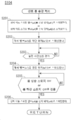
도 8은 도 7의 산포 붐 승강 처리의 컨트롤러에 의한 순서를 나타내는 플로우 차트이다.
도 9는 도 5의 어큐뮬레이터의 작동을 나타내는 타임 차트이다.
도 10은 본 발명의 다른 실시형태에 의한 자주식 약제 산포기의 정면도이다.
도 11은 도 10의 자주식 약제 산포기의 유압 회로의 일부를 나타내는 회로도이다.1 is a perspective view of a self-propelled drug spreader according to a preferred embodiment of the present invention.
Figure 2 is a left side view of the self-propelled drug spreader of Figure 1;
3 is a plan view of the self-propelled drug spreader of FIG. 1.
Figure 4 is a front view of the self-propelled drug spreader of Figure 1;
5 is a circuit diagram showing a part of the hydraulic circuit of the self-propelled drug spreader of FIG. 1.
6 is an enlarged view of a main part of the self-propelled drug spreader of FIG. 1.
7 is a flow chart showing the procedure of control by the controller of FIG. 5.
FIG. 8 is a flowchart showing a procedure performed by the controller of the scattering boom lifting process of FIG. 7.
9 is a time chart showing the operation of the accumulator of FIG. 5.
Fig. 10 is a front view of a self-propelled drug spreader according to another embodiment of the present invention.
11 is a circuit diagram showing a part of the hydraulic circuit of the self-propelled drug spreader of FIG. 10.
이하, 첨부된 도면을 참조해서 본 발명의 바람직한 실시형태에 대해 상세하게 설명한다. 또한, 실시예의 설명에 있어서는 기체의 전진 방향을 향해서 좌우 방향을 각각 좌, 우라고 하고, 전진 방향을 전방, 후진 방향을 후방이라고 하지만, 본 발명의 구성을 한정하는 것은 아니다.Hereinafter, preferred embodiments of the present invention will be described in detail with reference to the accompanying drawings. In addition, in the description of the embodiments, the left and right directions are referred to as left and right, respectively, toward the forward direction of the aircraft, and the forward direction is referred to as forward and the backward direction is referred to as rear, but the configuration of the present invention is not limited.
(전체 구성)(Full configuration)
자주식 약제 산포기(1)의 전체 구성예를 구체적으로 설명한다.An example of the entire configuration of the self-propelled drug disperser 1 will be described in detail.
자주식 약제 산포기(1)는 도 1에 사시도, 도 2에 좌측면도, 도 3에 평면도, 도 4에 정면도를 각각 나타내는 바와 같이 자주식의 주행 차체(A)와, 상기 주행 차체(A) 상에 설치된 캐빈(K)과, 약제를 저류하는 약제 탱크(M)와, 상기 약제 탱크(M)로부터 공급된 약제를 포장에 산포하는 산포 붐(b1)을 갖는 약제 산포 장치(B)를 구비해서 구성되어 있다.The self-propelled drug spreader 1 is on the self-propelled traveling vehicle body A and the traveling vehicle body A as shown in a perspective view in Fig. 1, a left side view in Fig. 2, a plan view in Fig. 3, and a front view in Fig. 4, respectively. A drug dispersing device (B) having an installed cabin (K), a drug tank (M) for storing drugs, and a dispersing boom (b1) for distributing drugs supplied from the drug tank (M) onto the packaging. Has been.
주행 차체(A)는 메인 프레임(a1)과, 운전 좌석(a2)과, 스티어링 핸들(a3)과, 전륜(a4)과 후륜(a5)을 포함하는 구성이다. 메인 프레임(a1)은 주행 차체(A)의 전후로 연장되어 형성되어 있다. 운전 좌석(a2)은 오퍼레이터가 승용 방제기(1)의 운전 조작을 할 때에 착좌하기 위한 좌석이다. 운전 좌석(a2)의 주위의 적절한 위치에는 산포 붐(b1)의 개폐나 약제의 산포 등의 동작을 제어하기 위한 조작 스위치나 키 스위치 등을 배합한 조작반(a6)이 배치되어 있다.The running vehicle body A has a structure including a main frame a1, a driver's seat a2, a steering handle a3, and a front wheel a4 and a rear wheel a5. The main frame a1 is formed to extend in front of and behind the traveling vehicle body A. The driver's seat a2 is a seat for seating when the operator performs a driving operation of the passenger control device 1. At an appropriate position around the driver's seat a2, an operation panel a6 incorporating an operation switch or key switch for controlling operations such as opening and closing of the dispersing boom b1 or dispersing of drugs is disposed.
운전 좌석(a2) 전방에 세워서 설치하는 스티어링 핸들(a3)은 오퍼레이터에 의한 회동 조작에 의해 적어도 좌우의 전륜(a4, a4)을 조타함으로써 자주식 약제 산포기(1)의 진행 방향을 변경한다. 즉, 전륜(a4, a4)은 적어도 스티어링 핸들(a3)의 회동 조작에 의해 조타되는 조타륜이다.The steering handle a3 installed upright in front of the driver's seat a2 changes the traveling direction of the self-propelled drug spreader 1 by steering at least the left and right front wheels a4 and a4 by a rotation operation by an operator. That is, the front wheels a4 and a4 are steering wheels that are steered by at least a rotation operation of the steering handle a3.
전륜(a4)과 후륜(a5)은 보닛(a7) 내의 엔진의 동력이 트랜스미션 케이스 내(도시하지 않음)에서 적당히 변속되고, 변속된 동력이 전달되어서 회전 구동한다.In the front wheel a4 and the rear wheel a5, the power of the engine in the bonnet a7 is suitably shifted in the transmission case (not shown), and the shifted power is transmitted to rotate and drive.
캐빈(K)은 운전 좌석(a2) 및 그 주변의 기기류, 스티어링 핸들 등을 둘러쌈으로써 승원실을 형성하는 것이다. 캐빈(K)은 약제 탱크(M)와 산포 붐(b1) 사이에 배치되어 있다. 캐빈(K)은 캐빈 프레임(k1), 캐빈 루프(k2), 좌우의 개폐 도어(k3L, k3R) 등으로 구성되어 있다.The cabin K forms a passenger compartment by enclosing the driver's seat a2 and surrounding equipment, steering handles, and the like. The cabin K is arranged between the medicine tank M and the dispersion boom b1. The cabin K is composed of a cabin frame k1, a cabin roof k2, and left and right opening and closing doors k3L and k3R.
약제 탱크(M)는 약제를 저류하는 용기이다. 약제 탱크(M)는 평면으로부터 볼 때에 도 3에 나타내는 바와 같이 캐빈(K)의 후방측에 배치되어 있으며, 운전 좌석(a2)의 좌우 양측 및 후방측을 둘러싸도록 コ자상으로 형성되고, 메인 프레임(a1) 상에 착탈 가능하게 탑재되어 있다. 또한, 약제 탱크(M)에 저장되는 약제는 비료, 농약 등을 용매(예를 들면, 물)에 용해시킨 액체 및 비료, 농약 등의 고형분을 포함하는 액체(예를 들면, 물) 등의 액상물이다.The medicine tank M is a container for storing medicines. When viewed from the top, the medicine tank M is disposed on the rear side of the cabin K as shown in Fig. 3, and is formed in a U shape so as to surround both left and right sides and the rear side of the driver's seat a2, and the main frame It is mounted detachably on (a1). In addition, the drugs stored in the drug tank (M) are liquids in which fertilizers, pesticides, etc. are dissolved in a solvent (e.g., water), and liquids (e.g., water) containing solids such as fertilizers and pesticides. It's water.
(약제 산포 장치)(Pharmaceutical dispersion device)
약제 산포 장치(B)는 포장에 산포하는 산포 붐(b1)과, 상기 산포 붐(b1)을 주행 차체(A)에 지가(支架)하는 지가 장치(b2)를 구비해서 구성되어 있다.The drug dispersing device (B) is configured to include a dispersing boom (b1) to disperse on a pavement, and a distributing device (b2) for distributing the dispersing boom (b1) to the traveling vehicle body (A).
산포 붐(b1)은 주행 차체(2)의 전방에 위치하는 센터 붐(b1F)과, 양측방에 위치하는 사이드 붐(b1L, b1R)으로 구성되어 있다.The scatter boom b1 is composed of a center boom b1F located in front of the traveling body 2 and side booms b1L and b1R located in both sides.
센터 붐(b1F)은 주행 차체(2)의 차폭 방향에 수평으로 연장되어 있다. 또한, 센터 붐(b1F)에는 약제를 안개형상으로 분사하는 노즐(bn)이 간격을 두고 복수 배치되어 있다.The center boom b1F extends horizontally in the vehicle width direction of the traveling vehicle body 2. Further, on the center boom b1F, a plurality of nozzles bn for spraying drugs in the form of fog are disposed at intervals.
사이드 붐(b1L, b1R)은 센터 붐(b1F)의 좌우 양측에 회동 가능하게 배치된다. 사이드 붐(b1L, b1R)에는 약제를 안개형상으로 산포하는 노즐(bn)이 간격을 두고 복수 배치되어 있다. 사이드 붐(b1L, b1R)의 회동에 의해 산포 붐(b1)은 주행 차체(A)의 차폭 방향(좌우 방향)으로 연장되도록 전체가 대략 일직선상이 되는 산포 자세와, 사이드 붐(b1L, b1R)이 주행 차체(2)의 좌우 양측을 따르는 수납 자세로 스위칭 가능하게 되어 있다. 이렇게 구성된 산포 붐(b1)은 산포 자세에 있어서는 자주식 약제 산포기(1) 전방측의 좌우로 폭 넓게 약제를 산포할 수 있다.The side booms b1L and b1R are arranged to be rotatable on both left and right sides of the center boom b1F. On the side booms b1L and b1R, a plurality of nozzles bn for dispersing drugs in a mist shape are arranged at intervals. With the rotation of the side booms b1L and b1R, the scattering boom b1 extends in the width direction (left and right direction) of the traveling body A so that the entire spreading posture and side booms b1L and b1R are in a straight line. It is possible to switch to the storage posture along the left and right sides of the traveling body 2. The dispersing boom b1 configured in this way can disperse the drugs widely to the left and right of the front side of the self-propelled drug disperser 1 in the dispersing posture.
지가 장치(b2)는 도 2 및 도 3에 나타내어지는 바와 같이 주행 차체(A)에 산포 붐(b1)을 승강 가능하게 지지하는 장치이며, 승강 실린더(b21)의 신장 또는 단축에 의해 회동하는 승강 링크(b20)와, 승강 링크(b20)의 전단과 연결된 부착 프레임(b21)과, 부착 프레임(b22)에 부착되어 승강 링크(b20)의 회동에 의해 상하 이동하는 승강 프레임(b23)과, 양측방의 사이드 붐(b1L, b1R)을 대략 수평으로 회동해서 개폐하는 개폐 실린더(b24, b24)를 구비하여 구성되어 있다. 부착 프레임(b22)은 도 4에 나타내어지는 바와 같이 정면으로부터 볼 때 직사각형의 프레임형상을 이루고, 하부에 형성된 롤링 축(Y)에 의해 승강 프레임(b23)을 롤링 축(Y)을 중심으로 하여 회동 가능하게 피봇팅하도록 구성되어 있다.The land price device (b2) is a device that supports the scattering boom (b1) on the traveling vehicle body (A) so as to be elevated and lowered as shown in Figs. 2 and 3, and is rotated by elongation or shortening of the lifting cylinder (b21). The link b20, the attachment frame b21 connected to the front end of the elevating link b20, the elevating frame b23 attached to the attachment frame b22 and moving up and down by the rotation of the elevating link b20, and both sides It is constituted by including the opening and closing cylinders b24 and b24 for opening and closing the side booms b1L and b1R of the room by rotating substantially horizontally. As shown in FIG. 4, the attachment frame (b22) forms a rectangular frame shape when viewed from the front, and the lifting frame (b23) is rotated around the rolling axis (Y) by the rolling axis (Y) formed at the bottom. It is configured to pivot possible.
승강 프레임(b23)의 전방부에는 센터 붐(b1)(b1F)이 부착되고, 승강 프레임(b23)의 좌우 양측에는 각각 사이드 붐(b1L, b1R)이 차폭 방향으로 전개할 수 있도록 회동 가능하게 부착되어 있다. 이러한 구성에 의해 승강 프레임(b23)이 승강하면 산포 붐(b1)도 승강하도록 구성되어 있다.Center booms (b1) (b1F) are attached to the front part of the lifting frame (b23), and side booms (b1L, b1R) are pivotably attached to the left and right sides of the lifting frame (b23) so that they can be deployed in the vehicle width direction. Has been. With this configuration, when the lifting frame b23 is raised and lowered, the scattering boom b1 is also configured to be raised and lowered.
개폐 실린더(b24, b24)는 신장 또는 단축에 의해 주행 차체(A)의 차폭 방향으로 연장되는 산포 자세와, 주행 차체(A)의 좌우 양측을 따르는 수납 자세로 스위칭 가능하게 하는 것이며, 승강 프레임(b23) 및 사이드 붐(b1L, b1R)과 연결되고, 개폐 실린더(b24, b24)가 신장 또는 단축되면 양측방의 사이드 붐(b1L, b1R)이 회동하도록 구성되어 있다. 또한, 개폐 실린더(b24, b24)의 신장 또는 단축은 후술하는 컨트롤러(C)에 의해 제어된다.The opening/closing cylinders b24 and b24 are capable of switching to a dispersion posture extending in the vehicle width direction of the traveling body A by extension or shortening, and a storage posture along both left and right sides of the traveling body A, and the lifting frame ( b23) and the side booms b1L and b1R, and when the opening/closing cylinders b24 and b24 are extended or shortened, the side booms b1L and b1R on both sides are configured to rotate. Further, the extension or shortening of the opening/closing cylinders b24 and b24 is controlled by a controller C described later.
(산포 붐 제진 장치)(Scatter boom vibration suppression device)
도 4에 나타내어지는 바와 같이 승강 프레임(b23) 상에는 승강 실린더(b24) 내의 압력 변동을 흡수하는 어큐뮬레이터(U)가 부착되어 있다.As shown in FIG. 4, on the lifting frame b23, the accumulator U which absorbs pressure fluctuations in the lifting cylinder b24 is attached.
도 5는 자주식 약제 산포기(1)의 유압 회로의 일부를 나타내는 회로도이다.5 is a circuit diagram showing a part of the hydraulic circuit of the self-propelled drug spreader 1.
도 5에 나타내어지는 바와 같이 산포 붐(b1)의 제진 기구는 어큐뮬레이터(U)와, 승강 실린더(b21)와 어큐뮬레이터(U)를 연통하는 작동유의 급배 통로에 설치된 개폐 밸브(u1)와, 개폐 밸브(u1)의 개폐를 제어 가능한 컨트롤러(C)를 구비해서 구성된다.As shown in Fig. 5, the vibration suppression mechanism of the scattering boom b1 includes an on/off valve u1 provided in the supply/discharge passage of hydraulic oil that communicates the accumulator U, the lifting cylinder b21 and the accumulator U, and an on/off valve. It is comprised with the controller C which can control the opening and closing of (u1).
유압 펌프인 제 1~2 펌프(P1, P2)는 엔진의 동력에 의해 구동되는 정용량형의 기어 펌프에 의해 구성되어 있다. 제 1~2 펌프(P1, P2)로부터 토출되는 작동유를 유통시키는 토출 유로(100)는 일정 유량을 분류하는 제 1 정분류 밸브(u2)와 접속되어 있다. 제 1 정분류 밸브(u2)는 제 1 유로(101)에 의해 제 2 정분류 밸브(u3)와 접속되어 있다. 제 2 정분류 밸브(u3)는 제 3 펌프(P3)로부터 토출되는 토출유(파일럿유)를 유통시키는 토출 유로(100a)가 접속되어 있다. 제 2 유로(102)에 의해 상하 이동 스위칭 밸브(u4)와 접속되어 있다.The first to second pumps P1 and P2, which are hydraulic pumps, are constituted by constant displacement gear pumps driven by the power of the engine. The
상하 이동 스위칭 밸브(u4)는 전자 스위칭 밸브이며, 승강 실린더(b21)를 신장시키는 작동 위치로서의 신장 위치(u41)와, 승강 실린더(b21)를 수축시키는 작동 위치로서의 수축 위치(u42)와, 승강 실린더(b24)를 정지시키는 정지 위치(u43)로 스위칭 가능하게 되어 있다.The vertical movement switching valve u4 is an electromagnetic switching valve, an extended position u41 as an operating position for extending the lifting cylinder b21, a contracted position u42 as an operating position for contracting the lifting cylinder b21, and lifting Switching to the stop position u43 for stopping the cylinder b24 is enabled.
상하 이동 스위칭 밸브(u4)는 제 2 유로(102) 외 좌우의 승강 실린더(b21, b21) 및 개폐 밸브(u1)와 연통하는 제 3 유로(103)와, 작동유 탱크(T)에 작동유를 되돌리는 배출 유로(104)와 연결되어 있다. 제 2 유로(102)와 배출 유로(104) 사이에는 릴리프 밸브(u5)가 설치되어 있으며, 제 2 유로(102)의 유압이 설정값을 초과했을 경우에 개변되어 배출 유로(104)로 유압을 배출하도록 되어 있다.The vertical movement switching valve u4 supplies hydraulic oil to the hydraulic oil tank T and the
상하 이동 스위칭 밸브(u4)가 신장 위치(u41)로 스위칭되면 제 2 유로(102) 및 제 3 유로(103)가 연통되고, 이에 따라 제 1~2 펌프(P1, P2)로부터 토출되는 작동유는 토출 유로(100), 제 1 유로(101), 제 2 유로(102), 및 제 3 유로(103)를 통해 승강 실린더(b21, b21)의 피스톤측실(b211, b211)로 유입된다. 이에 따라 승강 실린더(b21, b21)가 신장되기 때문에 이것에 따라 승강 링크(b20)가 상방으로 회동되어 승강 프레임(b23)이 상방으로 이동하고, 산포 붐(b1)은 승강 프레임과 함께 주행 차체(2)에 대해서 상승한다.When the vertical movement switching valve u4 is switched to the extended position u41, the
상하 이동 스위칭 밸브(u4)가 수축 위치(u42)로 스위칭되면 배출 유로(104)와 제 3 유로(103)가 연통된다. 이에 따라 승강 실린더(b21, b21)의 피스톤측실(b211, b211)의 작동유가 제 3 유로(103)와 배출 유로(104)를 통해서 작동유 탱크(T)로 되돌려진다. 이에 따라 승강 실린더(b21)가 수축되기 때문에 승강 링크(b20)가 하방으로 회동되어 승강 프레임(b23)이 하방으로 이동하고, 산포 붐(b1)은 승강 프레임(b23)과 함께 주행 차체(A)에 대하여 하강한다.When the vertical movement switching valve u4 is switched to the retracted position u42, the
상하 이동 스위칭 밸브(u4)가 정지 위치(u43)로 스위칭되면 제 3 유로(103)가 폐쇄된다. 이에 따라 제 3 유로(103)를 통해 피스톤측실(b211, b211)에 출입하는 작동유가 차단되어 주행 차체(A)에 대한 산포 붐(b1)의 높이가 유지된다.When the vertical movement switching valve u4 is switched to the stop position u43, the
개폐 밸브(u1)는 전자 스위칭 밸브이며, 승강 실린더(b21)의 피스톤측실(b211)과, 어큐뮬레이터(U)를 연통하는 연통 위치(u11)와, 연통을 차단하는 차단 위치(u12)를 스위칭 가능하게 되어 있다.The on-off valve (u1) is an electromagnetic switching valve, and the communication position (u11) for communicating the piston side chamber (b211) of the lifting cylinder (b21) and the accumulator (U), and the shut-off position (u12) for blocking communication can be switched. It is supposed to be done.
개폐 밸브(u1)가 연통 위치(u11)로 스위칭되면(개폐 밸브(u1)의 개방 제어) 제 3 유로(103)와 어큐뮬레이터(U)가 연통되고, 이에 따라 승강 실린더(b21)의 피스톤측실(b211)과, 어큐뮬레이터(U)가 연통된다. 이에 따라 작동유가 양자를 오고 감으로써 어큐뮬레이터(U)가 승강 실린더(b21) 내의 압력 변동을 흡수하고, 스프링 작용을 발휘하기 때문에 산포 붐(b1)의 진동이 억제되어 제진 기능이 발휘된다.When the opening/closing valve u1 is switched to the communication position u11 (open control of the opening/closing valve u1), the
개폐 밸브(u1)가 차단 위치(u12)로 스위칭되면(개폐 밸브(u1)의 폐쇄 제어) 제 3 유로(103)와 어큐뮬레이터(U)의 연통이 차단되고, 이에 따라 승강 실린더(b21)의 피스톤측실(b211)과, 어큐뮬레이터(U)의 연통이 차단된다. 이에 따라 어큐뮬레이터(U)에 의한 제진 기능을 정지하고, 산포 붐(b1)을 승강시킬 때의 응답성을 향상할 수 있다. 또한, 응답성이란 상세하게는 붐 상승 스위치 또는 붐 하강 스위치가 조작되고 나서 산포 붐(b1)의 승강 동작이 개시될 때까지의 신속성을 말한다.When the on/off valve u1 is switched to the shut-off position u12 (close control of the on/off valve u1), communication between the
컨트롤러(C)는 상하 이동 스위칭 밸브(u4) 및 개폐 밸브(u1)를 제어 가능한 제어 장치이며, CPU, ROM, RAM 등을 포함해서 구성되어 소정 제어용 프로그램이 기억되어 있다. 또한, 상하 이동 스위칭 밸브(u4) 및 개폐 밸브(u1)는 컨트롤러(C)와 전기적으로 접속되고, 컨트롤러(C)로 제어되어 포지션이 스위칭 가능하게 되어 있다. 또한, 컨트롤러(C)는 CPU, ROM, RAM 등을 사용하지 않고, 타이머, 릴레이 등을 사용하여 상하 이동 스위칭 밸브(u4) 및 개폐 밸브(u1)의 포지션을 제어 가능한 구성으로 해도 좋다.The controller C is a control device capable of controlling the vertical movement switching valve u4 and the on/off valve u1, and includes a CPU, ROM, RAM, etc., and stores a predetermined control program. Further, the vertical movement switching valve u4 and the on-off valve u1 are electrically connected to the controller C, and are controlled by the controller C, so that the positions can be switched. Further, the controller C may have a configuration capable of controlling the positions of the vertical movement switching valve u4 and the on-off valve u1 using a timer, a relay, or the like, without using a CPU, ROM, RAM, or the like.
컨트롤러(C)는 조작반(a6)과 전기적으로 접속되어 있으며, 조작반(a6)에 설치된 각종 조작 스위치의 조작을 신호로서 취득 가능하게 되어 있다. 즉, 작업자에 의한 조작반(a6)의 조작 정보를 취득 가능하게 되어 있다. 조작반(a6)에는 적어도 주행 차체(A)에 대하여 산포 붐(b1)을 상승시킬 때에 조작되는 도시하지 않은 붐 상승 스위치 및 주행 차체(A)에 대하여 산포 붐(b1)을 상승시킬 때에 조작되는 붐 하강 스위치, 자주식 약제 산포기(1)에 전원을 온할 때에 조작되는 키 스위치가 설치된다. 또한, 키 스위치는 온과 오프가 스위칭 가능한 조작 스위치이며, 키 스위치가 온 상태인 것이 자주식 약제 산포기(1)의 엔진 작동의 조건으로 되어 있다. 따라서, 작업자는 키 스위치를 온 조작한 후 소정 조작을 함으로써 자주식 약제 산포기(1)의 엔진을 작동시킬 수 있다. 컨트롤러(C)는 조작반(a6)으로부터의 신호에 의거하여 후술하는 제어를 실행하고, 상하 이동 스위칭 밸브(u4) 및 개폐 밸브(u1)의 포지션을 스위칭한다. 또한, 컨트롤러(C)에는 계시 수단으로서 타이머(c1)와, 키 스위치의 조작을 검지하여 회로 중의 접점 스위칭을 행하는 릴레이(c2)가 접속되어 있다.The controller C is electrically connected to the operation panel a6, and is capable of acquiring operations of various operation switches provided on the operation panel a6 as signals. That is, it is possible to acquire operation information of the operation panel a6 by an operator. The operation panel (a6) includes at least a boom lift switch (not shown) operated when raising the dispersion boom (b1) with respect to the traveling vehicle body (A) and a boom operated when raising the dispersion boom (b1) with respect to the traveling vehicle body (A). The descending switch and the self-propelled drug spreader 1 are provided with a key switch operated when the power is turned on. In addition, the key switch is an operation switch capable of switching on and off, and that the key switch is in the ON state is a condition for the engine operation of the self-propelled drug spreader 1. Therefore, the operator can operate the engine of the self-propelled drug spreader 1 by performing a predetermined operation after turning on the key switch. The controller C executes control to be described later based on a signal from the operation panel a6, and switches the positions of the vertical movement switching valve u4 and the on-off valve u1. Further, to the controller C, a timer c1 as a timing means and a relay c2 which detects an operation of a key switch and performs contact switching in a circuit are connected.
도 6은 자주식 약제 산포기(1)의 정면 요부 확대도이다.6 is an enlarged view of a main part of the self-propelled drug spreader 1 in front.
어큐뮬레이터(U)는 도 6에 나타내어지는 바와 같이 캐빈(K)의 전방의 승강 프레임(b23)의 좌우 대략 중앙에 배치되고, 주행 차체(2)의 차폭 방향에 있어서의 대략 중앙선 상에 위치하고 있다. 이에 따라 주행 차체(A)의 대략 중앙에 배치된 어큐뮬레이터(U)가 센터 마커가 되어 작업자는 자주식 약제 산포기(1)의 직진 조작이 용이해진다. 또한, 어큐뮬레이터(U)의 고장의 시인이 용이해지며, 유지보수성도 향상된다.As shown in FIG. 6, the accumulator U is disposed at the approximately center left and right of the lifting frame b23 in front of the cabin K, and is located on the approximately center line in the vehicle width direction of the traveling vehicle body 2. Accordingly, the accumulator U disposed approximately in the center of the traveling vehicle body A becomes a center marker, so that the operator can easily operate the self-propelled drug spreader 1 to go straight. In addition, it becomes easy to recognize a failure of the accumulator U, and maintainability is improved.
또한, 개폐 밸브(u1)는 도 6에 나타내어지는 어큐뮬레이터(U)의 하부에 배치된 하우징(X1)에 수용되어 있으며, 상하 이동 스위칭 밸브(u4)는 하우징(X1)의 측방에 근접해서 배치된 하우징(X2)에 수용되어 있다. 또한, 어큐뮬레이터(U)는 하우징(X1)에 착탈 가능하게 구성해도 좋다. 도 6에 나타내어지는 바와 같이 하우징(X1) 및 하우징(X2)은 승강 프레임(b23) 상에 근접해서 부착되어 고정되어 있으며, 개폐 밸브(u1) 및 상하 이동 스위칭 밸브(u4)는 근접해서 배치되어 있다. 또한, 하우징(X1) 및 하우징(X2)을 하나의 하우징으로 구성하고, 이 하나의 하우징에 개폐 밸브(u1)와 상하 이동 스위칭 밸브(u4)를 수용하도록 구성해도 좋다. 이렇게 개폐 밸브(u1) 및 상하 이동 스위칭 밸브(u4)를 일체적으로 직접 장착하는 구성에 의하면 조립성도 양호하며, 조립공 수를 삭감할 수 있음과 아울러, 배치 스페이스를 콤팩트하게 할 수 있다.In addition, the on-off valve u1 is accommodated in the housing X1 disposed under the accumulator U shown in FIG. 6, and the vertically moving switching valve u4 is disposed close to the side of the housing X1. It is accommodated in the housing X2. Further, the accumulator U may be configured to be detachable from the housing X1. As shown in Fig. 6, the housing X1 and the housing X2 are closely attached and fixed on the elevating frame b23, and the on/off valve u1 and the vertically moving switching valve u4 are arranged in close proximity. have. Further, the housing X1 and the housing X2 may be configured as one housing, and the on-off valve u1 and the vertical movement switching valve u4 may be accommodated in one housing. Thus, according to the configuration in which the on-off valve u1 and the vertical movement switching valve u4 are directly mounted integrally, the assembling property is good, the number of assembling labor can be reduced, and the arrangement space can be made compact.
이 어큐뮬레이터(U)와, 하우징(X1)과, 하우징(X2)은 주행 차체(2)의 기체의 전방부에 설치하는 구성으로 하고 있다. 구체적으로는 기체의 최전방부에 설치하는 구성으로 하고 있다. 이에 따라, 보수 관리가 용이해진다. 또한, 노즐(bn)이 부착된 산포 붐(b1)은 승강 프레임(b23)을 승강시킴으로써 임의의 위치로 승강할 수 있는 구성으로 하고 있다. 이 승강 프레임(b23)에 대해서 어큐뮬레이터(U)와, 하우징(X1)과, 하우징(X2)을 부착하는 구성으로 하고 있다.The accumulator U, the housing X1, and the housing X2 are configured to be installed in the front portion of the body of the traveling vehicle body 2. Specifically, it is configured to be installed in the foremost part of the body. Accordingly, maintenance management becomes easy. Further, the scattering boom b1 to which the nozzle bn is attached is configured to be able to move up and down to an arbitrary position by raising and lowering the lifting frame b23. The accumulator U, the housing X1, and the housing X2 are attached to the lifting frame b23.
이에 따라 어큐뮬레이터(U)와, 하우징(X1)과, 하우징(X2)은 각각의 위치 관계를 유지한 상태에서 임의의 위치로 승강시킬 수 있으므로 배관에 영향을 주는 일이 없고, 또한 보수 관리가 용이해진다.Accordingly, the accumulator (U), the housing (X1), and the housing (X2) can be moved up and down to an arbitrary position while maintaining their respective positional relationship, so there is no effect on the piping, and maintenance is easy. It becomes.
(개폐 밸브의 개폐 제어)(Open/close control of open/close valve)
도 7은 컨트롤러(C)에 의한 제어의 순서를 나타내는 플로우 차트이다.7 is a flow chart showing the procedure of control by the controller C.
컨트롤러(C)는 도 7의 플로우 차트에 나타내어지는 순서에 따라 개폐 밸브(u1) 및 상하 이동 스위칭 밸브(u4)를 제어한다. 또한, 초기 조건으로 하여 키 스위치는 오프 조작되어 있으며, 개폐 밸브(u1)는 차단 위치(u12)로 스위칭되어 있다.The controller C controls the on-off valve u1 and the vertical movement switching valve u4 according to the sequence shown in the flow chart of FIG. 7. Further, the key switch is operated off as an initial condition, and the on-off valve u1 is switched to the cut-off position u12.
컨트롤러(C)는 키 스위치가 온 조작된 신호를 취득하면(스텝 S101) 개폐 밸브(u1)를 연통 위치(u11)로 스위칭하도록 제어한다(스텝 S102). 이것에 의해 어큐뮬레이터(U)에 의한 제진 기능이 발휘되어 산포 붐(b1)의 진동이 억제된다. 이렇게 작업자에 의한 키 스위치의 온 조작과 연동해서 개폐 밸브(u1)를 개방하는 구성에 의하면 전원 온만으로 엔진 정지 중의 상태 또는 엔진 작동 중의 상태, 또는 작업 시에 있어서 확실하게 개폐 밸브(u1)가 개방 상태가 된다. 이에 따라, 종래와 같이 작업자가 수동 조작에 의해 개폐 밸브(u1)를 개방하는 시간이 생략되기 때문에 편리성이 향상된다. 또한, 작업 시에 작업자가 수동 조작에 의해 개폐 밸브(u1)를 개방하는 조작을 실념할 일도 없다. 또한, 개폐 밸브(u1)를 온오프하기 위한 스위치가 불필요해진다.The controller C controls to switch the on/off valve u1 to the communication position u11 when acquiring the signal in which the key switch is turned on (step S101) (step S102). Thereby, the vibration suppression function by the accumulator U is exhibited, and the vibration of the scattering boom b1 is suppressed. According to the configuration in which the on-off valve (u1) is opened in conjunction with the operator's ON operation of the key switch, the on-off valve (u1) is reliably opened in a state in which the engine is stopped or in operation, or during operation only by turning on the power. State. Accordingly, since the time for the operator to open the on-off valve u1 by manual operation as in the prior art is omitted, convenience is improved. In addition, there is no need for an operator to lose sight of the operation of opening the on-off valve u1 by manual operation during work. Further, a switch for turning on/off the on-off valve u1 becomes unnecessary.
이어서, 컨트롤러(C)는 붐 상승 스위치가 온 조작 또는 붐 하강 스위치가 온 조작된 신호를 취득하면(스텝 S103) 후술하는 산포 붐(b1)의 승강 처리를 실행한다(스텝 S104).Subsequently, when the controller C acquires a signal in which the boom raising switch is turned on or the boom lowering switch is turned on (step S103), it executes the raising and lowering processing of the spreading boom b1 to be described later (step S104).
또한, 컨트롤러(C)는 스텝 S102에 있어서 개폐 밸브(u1)를 연통 위치(u11)로 스위칭하도록 제어한 후 키 스위치가 오프 조작된 신호를 취득하면(스텝 S105) 개폐 밸브(u1)를 차단 위치(u12)로 스위칭하도록 제어한다(스텝 S106). 이에 따라 키 스위치가 오프 조작과 연동해서 어큐뮬레이터(U)에 의한 제진 기능이 정지된다. 이렇게 해서 비작업 시에 있어서는 어큐뮬레이터(U)에 의한 제진 기능을 자동으로 오프로 함으로써 주행 차체(A)에 대하여 산포 붐(b1)을 고정하는 구성에 의하면, 예를 들어 자주식 약제 산포기(1)를 수송할 때 등의 비작업 시에 산포 붐(b1)이 상하로 요동해서 외부의 장해물에 접촉할 우려를 방지할 수 있다. 또한, 어큐뮬레이터(U)를 분리하여 보수 관리를 행할 때 개폐 밸브(u1)는 차단 위치(u12)로 스위칭되어 있기 때문에 진애 등이 유압 회로 내에 침입하는 것을 방지할 수 있다.Further, the controller C controls the on-off valve u1 to switch to the communication position u11 in step S102, and then acquires a signal in which the key switch is turned off (step S105), the on-off valve u1 is turned off. Control is performed to switch to (u12) (step S106). Accordingly, the vibration suppression function by the accumulator U is stopped in conjunction with the off operation of the key switch. In this way, according to the configuration in which the dispersion boom b1 is fixed to the traveling vehicle body A by automatically turning off the vibration suppression function by the accumulator U at the time of non-work, for example, the self-propelled drug sprayer 1 It is possible to prevent the possibility of contact with external obstacles by the scattering boom (b1) swinging up and down during non-work, such as when transporting. In addition, since the on-off valve u1 is switched to the cut-off position u12 when the accumulator U is separated and maintenance is performed, dust or the like can be prevented from entering the hydraulic circuit.
도 8은 도 7의 산포 붐 승강 처리(스텝 S104)의 컨트롤러(C)에 의한 순서를 나타내는 플로우 차트이다. 컨트롤러(C)는 스텝 S103에 있어서 붐 상승 스위치가 온 조작 또는 붐 하강 스위치가 온 조작된 신호를 취득하면 붐 상승 스위치가 온 조작된 신호를 취득한 경우에는 상하 이동 스위칭 밸브(u4)를 신장 위치(u41)로 스위칭하여 산포 붐(b1)을 상승시킨다. 붐 하방 스위치가 온 조작된 신호를 취득한 경우에는 상하 이동 스위칭 밸브(u4)를 수축 위치(u42)로 스위칭하고, 산포 붐(b1)을 하강시킨다(스텝 S201).Fig. 8 is a flow chart showing a procedure performed by the controller C of the scattering boom lifting process (step S104) of Fig. 7. When the controller C acquires a signal in which the boom up switch is turned on or the boom down switch is turned on in step S103, and acquires the signal in which the boom up switch is turned on, the vertical movement switching valve u4 is moved to the extended position ( Switch to u41) and raise the scatter boom (b1). When a signal in which the boom lower switch is turned on is acquired, the vertical movement switching valve u4 is switched to the retracted position u42, and the scattering boom b1 is lowered (step S201).
동시에 개폐 밸브(u1)를 차단 위치(u12)로 바로 스위칭한다(스텝 S202). 이것에 의해 계속되는 산포 붐(b1)의 승강의 응답성을 향상시킬 수 있다.At the same time, the on-off valve u1 is immediately switched to the shut-off position u12 (step S202). Thereby, the responsiveness of the continuing elevation of the scattering boom b1 can be improved.
여기에서 컨트롤러(C)는 산포 붐(b1)의 승강 개시와 동시에 타이머(c1)를 기동하여 설정 시간(t)을 카운트한다(스텝 S203). 이 설정 시간(t)은 소정 단시간이 미리 설정되어 있으며, 예를 들면 1초 정도이다.Here, the controller C counts the set time t by starting the timer c1 at the same time as the start of raising and lowering the scattering boom b1 (step S203). This setting time t is set in advance for a predetermined short time, for example, about 1 second.
이어서, 컨트롤러(C)는 설정 시간(t)이 경과하면 개폐 밸브(u1)를 연통 위치(u11)로 스위칭한다(스텝 S204). 즉, 컨트롤러(C)는 산포 붐(b1)의 승강 동작의 개시 직후인 단시간만 개폐 밸브(u1)를 차단 위치(u12)로 바로 스위칭하고, 승강 개시 후의 산포 붐(b1)의 승강 동작 중에 있어서는 개폐 밸브(u1)를 연통 위치(u11)로 스위칭한다. 이것에 의해 산포 붐(b1)의 승강 조작 시에 신속한 응답성을 확보할 수 있고, 또한 계속되는 승강 개시 후의 산포 붐(b1)의 승강 동작 중에 있어서는 어큐뮬레이터(U)에 의한 제진 기능을 발휘해서 산포 붐(b1)의 진동을 저감할 수 있다. 그 결과, 산포 붐(b1)의 동작이 안정되어 안전성을 향상할 수 있다. 즉, 종래와 같이 산포 붐(b1)의 승강 동작이 완료된 후 개폐 밸브(u1)를 개방 제어하는 구성에 의하면 개폐 밸브(u1)를 개방했을 때에 승강 실린더(b21)와 어큐뮬레이터(U)의 작동유의 압력차에 의해 승강 실린더(b21)로부터 어큐뮬레이터(U)측으로 급속하게 작동유가 흘러 들어 오고, 그 결과 승강 실린더(b21)가 신장 또는 단축되어 산포 붐(b1)이 정지 위치보다 하강해서 동작이 불안정해질 우려가 있었지만 산포 붐(b1)의 승강 동작 중에 개폐 밸브(u1)를 개방 제어함으로써 승강 실린더(b21)와 어큐뮬레이터(U)의 작동유의 압력차를 해소하고, 산포 붐(b1)의 안정된 동작을 실현할 수 있다. 여기에서 설정 시간(t)은 0.5초~3초 이내로 설정되는 것이 바람직하고, 0.5초~1초 이내로 설정되는 것이 더 바람직하다.Subsequently, the controller C switches the on-off valve u1 to the communication position u11 when the set time t has elapsed (step S204). That is, the controller C immediately switches the on/off valve u1 to the shut-off position u12 for only a short time immediately after the start of the lifting operation of the spreading boom b1, and during the lifting operation of the spreading boom b1 after the start of lifting. The on-off valve u1 is switched to the communication position u11. As a result, rapid response can be ensured during the lifting operation of the scattering boom b1, and during the lifting operation of the scattering boom b1 after the continuation of lifting and lowering, the accumulator U provides a vibration suppression function. The vibration of (b1) can be reduced. As a result, the operation of the scattering boom b1 is stabilized and safety can be improved. That is, according to the configuration in which the on/off valve u1 is opened and controlled after the elevating operation of the scattering boom b1 is completed as in the related art, when the on/off valve u1 is opened, the hydraulic oil of the lifting cylinder b21 and the accumulator U Due to the pressure difference, hydraulic oil rapidly flows from the lifting cylinder (b21) to the accumulator (U) side, and as a result, the lifting cylinder (b21) is extended or shortened, causing the dispersion boom (b1) to descend from the stop position, resulting in unstable operation. Although there was a concern, by controlling the opening and closing valve u1 during the lifting operation of the dispersion boom (b1), the pressure difference between the hydraulic oil between the lifting cylinder (b21) and the accumulator (U) can be eliminated, and a stable operation of the dispersion boom (b1) can be achieved. I can. Here, the setting time t is preferably set within 0.5 seconds to 3 seconds, and more preferably within 0.5 seconds to 1 second.
계속해서, 컨트롤러(C)는 붐 상승 스위치 또는 붐 하강 스위치가 오프 조작된 신호를 취득하면(스텝 S205) 상하 이동 스위칭 밸브(u4)를 정지 위치(u43)로 스위칭하도록 제어한다(스텝 S206). 이에 따라 산포 붐(b1)의 승강이 정지되고, 도 7에 있어서의 산포 붐(b1) 승강 처리(스텝 S104)가 완료된다.Subsequently, the controller C controls to switch the vertical movement switching valve u4 to the stop position u43 when acquiring a signal in which the boom up switch or the boom down switch is turned off (step S205) (step S206). Thereby, the elevating and descending of the dispersion boom b1 is stopped, and the elevating process of the dispersion boom b1 in FIG. 7 (step S104) is completed.
또한, 도 7 및 도 8에는 도시되어 있지 않지만 붐 상승 스위치 또는 붐 하강 스위치를 소정 시간(약 0.5초부터 1초 정도)에 연속 조작하면 산포 붐(b1)의 승강은 행하지 않고, 개폐 밸브(u1)를 수동으로 폐쇄하는 구성으로 한다. 이 경우에 있어서 붐 상승 스위치 또는 붐 하강 스위치 대신에 다른 스위치나 레버류가 설치되어도 좋다. 이에 따라 작업자의 판단에 의해 어큐뮬레이터(U)를 작동시킬 필요가 없는 상황(예를 들면, 노면의 요철이 적은 상황)에 있어서 어큐뮬레이터(U)의 작동 정지가 용이하게 가능해진다. 또한, 어큐뮬레이터(U)를 다시 작동시킬 경우에는 붐 상승 스위치 또는 붐 하강 스위치를 소정 시간(약 0.5초부터 1초 정도)에 연속 조작한다. 이에 따라 개폐 밸브(u1)를 온오프하기 위한 스위치가 불필요해진다.In addition, although not shown in Figs. 7 and 8, if the boom raising switch or the boom lowering switch is continuously operated for a predetermined time (about 0.5 seconds to about 1 second), the spreading boom b1 is not raised and lowered, and the on/off valve u1 ) Is closed manually. In this case, other switches or levers may be provided instead of the boom raising switch or the boom lowering switch. This makes it possible to easily stop the operation of the accumulator U in a situation where it is not necessary to operate the accumulator U at the discretion of the operator (for example, a situation where the unevenness of the road surface is small). In addition, when operating the accumulator U again, the boom raising switch or the boom lowering switch is continuously operated at a predetermined time (about 0.5 seconds to about 1 second). Accordingly, a switch for turning on/off the on-off valve u1 becomes unnecessary.
또한, 기체에 진동 센서를 설치하고, 기체의 진동이 소정 이내의 수치이며, 소정 시간 이상 계속되면 자동으로 개폐 밸브(u1)를 폐쇄하여 어큐뮬레이터(U)를 작동 정지로 해도 좋다. 단, 적어도 수 회 소정값 이상의 진동 수치가 계속되면 자동으로 개폐 밸브(u1)를 개방하여 어큐뮬레이터를 작동시키는 구성으로 한다.Further, a vibration sensor may be provided on the gas, and when the vibration of the gas is within a predetermined value and continues for a predetermined time or longer, the on-off valve u1 may be automatically closed to stop the accumulator U from operating. However, if the vibration value of at least several times or more continues, the on-off valve u1 is automatically opened to operate the accumulator.
또한, 붐 상승 스위치 및 붐 하강 스위치는 캐빈(K) 내의 운전 좌석(a2)에 착좌한 상태에서 조작 가능한 위치에 설치되어 있지만 캐빈(K) 외에도 설치하는 구성으로 하고 있다. 도 2에 나타내는 바와 같이 개폐 도어(k3L)의 측방을 사이드 붐(b1L)이 통과하고 있기 때문에 승강 시에 사이드 붐(b1L)의 하방을 빠져나가서 타고 내리는 것도 가능하지만, 승강 시에 사이드 붐(b1L)을 승강시킴으로써 타고 내리기가 쉬워진다. 그래서 캐빈(K) 외에 설치되어 있는 붐 상승 스위치 또는 붐 하강 스위치를 조작해서 사이드 붐(b1L)을 승강 가능하게 구성하고 있다.In addition, the boom raising switch and the boom lowering switch are provided at positions that can be operated while seated on the driver's seat a2 in the cabin K, but are provided in addition to the cabin K. As shown in Fig. 2, since the side boom b1L passes through the side of the opening/closing door k3L, it is possible to get on and off the lower side of the side boom b1L when ascending and descending, but the side boom b1L ) To make it easier to get on and off. Therefore, the side boom b1L is configured to be able to move up and down by operating the boom raising switch or the boom lowering switch provided outside the cabin K.
사이드 붐(b1L, b1R)은 승강 프레임(b23)에 대하여 독립적으로 승강 가능하게 구성되어 있으며, 도 5의 유압 회로와는 독립된 전기식의 유압 실린더(ES)로 승강 가능하게 구성되어 있다. 이 경우, 엔진은 정지되어 유압은 작동하고 있지 않아도 사이드 붐(b1L, b1R)은 캐빈(K) 외의 붐 상승 스위치 및 붐 하강 스위치를 조작함으로써 배터리의 전원을 이용해서 전기식의 유압 실린더(ES)를 구동함으로써 승강한다. 이에 따라 캐빈(K) 내로의 승강이 용이해진다.The side booms b1L and b1R are configured to be liftable independently from the lift frame b23, and are configured to be liftable with an electric hydraulic cylinder ES independent from the hydraulic circuit of FIG. 5. In this case, even though the engine is stopped and hydraulic pressure is not operating, the side booms b1L and b1R operate the boom up switch and the boom down switch other than the cabin K to operate the electric hydraulic cylinder ES using the power of the battery. It goes up and down by driving. Accordingly, it becomes easy to ascend and descend into the cabin K.
도 9는 도 5의 어큐뮬레이터(U)의 작동을 나타내는 타임 차트이다.9 is a time chart showing the operation of the accumulator U of FIG. 5.
또한, 도 9에 있어서 어큐뮬레이터(U)의 온 시 개폐 밸브(u1)는 연통 위치(u11)에 있으며, 어큐뮬레이터(U)의 오프 시 차단 위치(u12)에 있다. 도 9에 나타내어지는 바와 같이 키 스위치 온일 때 통상 어큐뮬레이터(U)는 온이 되지만 붐 상승 스위치가 온 조작 또는 붐 하강 스위치가 온 조작된 직후로부터 설정 시간(t) 동안 어큐뮬레이터(U)는 오프가 되도록 구성된다. 또한, 설정 시간(t)은 상술한 바와 같이 미리 단시간(예를 들면, 1초 정도)이 설정되어 있지만 산포 붐(b1)의 중량이나 작업자의 니즈에 맞춘 산포 붐(b1)의 승강의 응답성을 실현하기 위해서 조작반(a6)의 조작에 의해 소정 범위(예를 들면, 0.5초~3초 정도)로 조정 가능하게 되어 있다.In addition, in FIG. 9, when the accumulator U is on, the on-off valve u1 is in the communication position u11, and when the accumulator U is off, the on-off valve u1 is in the cut-off position u12. As shown in Fig. 9, when the key switch is on, the accumulator (U) is normally turned on, but the accumulator (U) is turned off for a set time (t) from immediately after the boom up switch is turned on or the boom down switch is turned on. Is composed. In addition, the setting time (t) is set in advance for a short time (e.g., about 1 second) as described above, but the responsiveness of raising and lowering the dispersion boom (b1) according to the weight of the dispersion boom (b1) and the needs of the operator In order to realize this, it is possible to adjust to a predetermined range (for example, about 0.5 to 3 seconds) by operation of the operation panel a6.
본 발명은 이상의 실시형태에 한정되는 일 없이 특허청구범위에 기재된 발명의 범위 내에서 여러 가지의 변경이 가능하며, 그들도 본 발명의 범위 내에 포함되는 것은 말할 필요도 없다.It goes without saying that the present invention is not limited to the above embodiments, and various modifications are possible within the scope of the invention described in the claims, and they are also included within the scope of the present invention.
예를 들면, 상기 실시형태에 있어서는 도 4에 나타내어지는 바와 같이 부착 프레임(b22)의 하부에 형성된 롤링 축(Y)에 의해 승강 프레임(b23)을 롤링 축(Y)을 중심으로 하고, 회동 가능하게 피봇팅하도록 구성했지만 도 10에 나타내어지는 바와 같이 단동식 롤용 실린더(b25)를 승강 프레임(b23)의 좌우 일단측에 배치하고, 좌우 타단측에 댐퍼(b26)를 배치하고, 단동식 롤용 실린더(b25)의 신장 또는 단축에 의해 승강 프레임(b23)을 롤링 제어하는 구성으로 해도 좋다. 이때 좌우 타단측에 배치된 댐퍼(b26)에 의해 단동식 롤용 실린더(b25)의 리턴 동작을 행함으로써 압축 스프링 등의 탄성체를 사용하는 경우에 비해 승강 프레임의 롤링 방향의 흔들림 진동을 억제할 수 있고, 안정된 롤 제어가 가능해진다.For example, in the above embodiment, as shown in Fig. 4, the lifting frame b23 is centered on the rolling axis Y by the rolling axis Y formed under the attachment frame b22, and can be rotated. Although it was configured to pivot so as to be pivoted, as shown in FIG. 10, a single-acting roll cylinder (b25) is disposed on the left and right one ends of the lifting frame (b23), and a damper (b26) is disposed on the other left and right ends, and the single-acting roll cylinder is It is good also as a structure in which rolling control of the lifting frame b23 is carried out by the extension or shortening of (b25). At this time, by performing the return operation of the single-acting roll cylinder (b25) by the dampers (b26) disposed on the other ends of the left and right, it is possible to suppress the shaking vibration in the rolling direction of the elevating frame compared to the case of using an elastic body such as a compression spring. , Stable roll control becomes possible.
도 11은 다른 실시형태에 의한 자주식 약제 산포기(1)의 유압 회로의 일부를 나타내는 회로도이다. 다른 실시형태에 의한 자주식 약제 산포기(1)의 유압 회로는 도 5에서 나타낸 유압 회로의 구성에 추가하여 제 1 정분류 밸브(u2)에 제 4 유로(105)를 접속하고, 또한 제 4 유로(105)에 단동식 롤용 실린더(b25)를 신장시키는 작동 위치로서의 신장 위치(u51)와, 수축시키는 작동 위치로서의 수축 위치(u52)와, 정지시키는 정지 위치(u53)로 스위칭 가능한 전자 스위칭 밸브인 단동식 롤용 실린더 스위칭 밸브(u5)를 접속한다. 승강 프레임(b23)은 롤링 축(Y)을 중심으로 해서 회동 가능하게 피봇팅되어 있으며, 승강 프레임(b23)의 롤링 방향의 제진을 어큐뮬레이터(U2)에 의해 행하는 구성으로 하고 있다.11 is a circuit diagram showing a part of a hydraulic circuit of the self-propelled drug spreader 1 according to another embodiment. In the hydraulic circuit of the self-propelled drug spreader 1 according to another embodiment, in addition to the configuration of the hydraulic circuit shown in Fig. 5, the
도 11에 나타내어지는 바와 같이 단동식 롤용 실린더 스위칭 밸브(u5)는 제 5 유로(106)와 접속되고, 제 5 유로(106)는 단동식 롤용 실린더(b25)의 피스톤측실(b251)과, 롤용 어큐뮬레이터(U2)를 연통하는 연통 위치(u71)와, 연통을 차단하는 차단 위치(u72)를 스위칭 가능한 제 2 개폐 밸브(u7)와 접속된다. 컨트롤러(C)는 키 스위치가 온 조작된 신호를 취득하면 개폐 밸브(u7)를 연통 위치(u71)로 스위칭하도록 제어한다. 이에 따라 어큐뮬레이터(U2)에 의한 제진 기능이 발휘되어 승강 프레임(b23)의 롤링 방향의 진동을 억제할 수 있다. 또한, 어큐뮬레이터(U2)를 분리하여 보수 관리를 행할 때 개폐 밸브(u7)는 차단 위치(u72)로 스위칭되어 있기 때문에 진애 등이 유압 회로 내에 침입하는 것을 방지할 수 있다.As shown in Fig. 11, the single-acting roll cylinder switching valve u5 is connected to the
또한, 단동식 롤용 실린더 스위칭 밸브(u5)는 작동유 탱크(T)에 작동유를 되돌리는 제 2 배출 유로(107)와 접속되고, 제 4 유로(105) 및 제 2 배출 유로(107) 사이에는 릴리프 밸브(u6)가 설치되어 있다. 또한, 도시되어 있지 않지만 단동식 롤용 실린더 스위칭 밸브(u5) 및 제 2 개폐 밸브(u7)는 컨트롤러(C)와 접속되고, 컨트롤러(C)에 의해 포지션이 제어 가능하게 되어 있다. 또한, 단동식 롤용 실린더 스위칭 밸브(u5) 및 제 2 개폐 밸브(u7)는 도 10에서 나타내어지는 하우징(X3) 내에 수용된다.In addition, the single-acting roll cylinder switching valve u5 is connected to the
여기에서 기체의 평면으로부터 볼 때에 있어서 기체 진행 방향 중심선에 대하여 좌측 또는 우측 중 어느 일방측에 어큐뮬레이터(U, U2)를 배치하고, 타방측에 유압 밸브를 배치하도록 구성해도 좋다. 이렇게 중량이 무거운 어큐뮬레이터와 유압 밸브를 기체 진행 방향 중심선에 대하여 좌우로 나누어 배치함으로써 기체의 좌우 밸런스가 향상된다.Here, when viewed from the plane of the gas, the accumulators U and U2 may be disposed on either the left or the right side of the center line in the gas traveling direction, and the hydraulic valve may be disposed on the other side. By distributing the heavy accumulator and hydraulic valve to the left and right with respect to the center line in the gas traveling direction, the left and right balance of the gas is improved.
또한, 어큐뮬레이터(U, U2)로의 개폐 밸브가 개방되어 있으며, 어큐뮬레이터(U, U2)가 작동 가능한 상태를 알리는 표시등을 키 스위치의 부근이나 조작부의 핸들 주변에 설치하는 구성으로 해도 좋다. 이에 따라 작업자가 정차 중이나 주행 중(작업, 이동)에 어큐뮬레이터(U, U2)의 작동 상황을 용이하게 확인할 수 있게 된다. 이러한 구성에 의하면, 특히 어큐뮬레이터(U, U2)의 작동의 온오프 스위치가 없을 경우(키 스위치의 온오프에 연동해서 어큐뮬레이터(U, U2)의 작동을 자동으로 행하는 구성)에 유효하다.Further, the on-off valve to the accumulators U and U2 may be opened, and an indicator indicating a state in which the accumulators U and U2 can be operated may be provided in the vicinity of the key switch or around the handle of the operation unit. Accordingly, the operator can easily check the operating conditions of the accumulators U and U2 while stopping or driving (working, moving). This configuration is particularly effective when there is no on-off switch for operating the accumulators U, U2 (a configuration in which the accumulators U, U2 are automatically operated in conjunction with on-off of the key switch).
A: 주행 차체
a1: 메인 프레임
a2: 운전 좌석
a3: 스티어링 핸들
a4: 전륜
a5: 후륜
a6: 조작반
a7: 보닛
B: 약제 산포 장치
bn: 노즐
b1: 산포 붐
b2: 지가 장치
b20: 승강 링크
b21: 승강 실린더
b22: 부착 프레임
b23: 승강 프레임
b24: 개폐 실린더
b25: 단동식 롤용 실린더
K: 캐빈
k1: 캐빈 프레임
k2: 캐빈 루프
k3L, k3R: 개폐 도어
T: 작동유 탱크
U: 어큐뮬레이터
U2: 롤용 어큐뮬레이터
P1: 제 1 펌프
P2: 제 2 펌프
u1: 개폐 밸브
u2: 제 1 정분류 밸브
u3: 제 2 정분류 밸브
u4: 상하 이동 스위칭 밸브
u5: 단동식 롤용 실린더 스위칭 밸브
u6: 릴리프 밸브
u7: 제 2 개폐 밸브
Y: 롤링 축A: running body a1: main frame
a2: driving seat a3: steering handle
a4: front wheel a5: rear wheel
a6: control panel a7: bonnet
B: drug dispersing device bn: nozzle
b1: scatter boom b2: land price device
b20: lifting link b21: lifting cylinder
b22: attachment frame b23: elevating frame
b24: open/close cylinder b25: single-acting roll cylinder
K: cabin k1: cabin frame
k2: Cabin roof k3L, k3R: opening door
T: hydraulic oil tank U: accumulator
U2: Roll accumulator P1: 1st pump
P2: second pump u1: on-off valve
u2: first positive classification valve u3: second positive classification valve
u4: vertical movement switching valve u5: cylinder switching valve for single-acting rolls
u6: relief valve u7: second on-off valve
Y: rolling axis
Claims (4)
작업자의 조작을 받아들이는 조작부(a6)와,
승강 실린더(b21)의 신장 또는 단축에 의해 승강 가능하게 구성된 약제 산포부(b1)와,
승강 실린더(b21)와 접속되고, 가압된 작동 유체를 저류하는 어큐뮬레이터(U)와,
승강 실린더(b21)와 어큐뮬레이터(U)를 연통하는 통로를 개폐하는 개폐 밸브(u1)와,
조작부(a6)의 조작 정보를 취득 가능하게 구성되고, 승강 실린더(b21)의 신장 또는 단축 및 개폐 밸브(u1)의 개폐를 제어 가능하게 구성된 제어부(C)를 구비하는 자주식 약제 산포기로서,
조작부(a6)는 자주식 약제 산포기의 전원을 온하는 키 스위치를 구비하고,
제어부(C)는 키 스위치가 조작되어 자주식 약제 산포기의 전원을 온된 것을 조건으로 하여 개폐 밸브(u1)를 개방 제어하고, 또한
키 스위치가 조작되어 자주식 약제 산포기의 전원이 오프된 것을 조건으로 하여 개폐 밸브(u1)를 폐쇄 제어하는 것을 특징으로 하는 자주식 약제 산포기.A running vehicle body (A) that runs the aircraft,
An operation unit (a6) that accepts an operator's operation,
A drug dispersing portion (b1) configured to be elevated by elongation or shortening of the elevating cylinder (b21),
An accumulator (U) connected to the lifting cylinder (b21) and storing the pressurized working fluid,
An on-off valve u1 for opening and closing a passage communicating the lifting cylinder b21 and the accumulator U,
A self-propelled drug spreader comprising a control unit (C) configured to be capable of acquiring operation information of the operation unit (a6), and configured to control elongation or shortening of the lifting cylinder (b21) and opening and closing of the on/off valve (u1),
The operation unit (a6) is provided with a key switch to turn on the power of the self-propelled drug spreader,
The control unit C controls the opening of the on-off valve u1 on condition that the key switch is operated to turn on the power of the self-propelled drug disperser, and
A self-propelled drug spreader, characterized in that the on-off valve (u1) is closed and controlled on condition that the power of the self-propelled drug spreader is turned off by a key switch being operated.
제어부(C)는 조작부(a6)에 있어서 승강 실린더(b21)를 신장 또는 단축하는 조작이 이루어지면,
소정 설정 시간(t) 동안 개폐 밸브(u1)를 폐쇄 제어한 후 개방 제어하도록 구성된 것을 특징으로 하는 자주식 약제 산포기.The method of claim 1,
When the control unit C is operated to extend or shorten the lifting cylinder b21 in the operation unit a6,
Self-propelled drug spreader, characterized in that configured to control the opening after closing the on-off valve (u1) for a predetermined set time (t).
설정 시간(t)이 0.5초로부터 1초의 범위 내인 것을 특징으로 하는 자주식 약제 산포기.The method of claim 2,
A self-propelled drug spreader, characterized in that the set time (t) is within a range of 0.5 seconds to 1 second.
조작부(a6)의 조작에 의해 설정 시간(t)을 조절 가능하게 한 것을 특징으로 하는 자주식 약제 산포기.The method of claim 2,
Self-propelled drug spreader, characterized in that the set time (t) can be adjusted by the operation of the operation unit (a6).
Applications Claiming Priority (2)
| Application Number | Priority Date | Filing Date | Title |
|---|---|---|---|
| JPJP-P-2019-141750 | 2019-07-31 | ||
| JP2019141750A JP7221165B2 (en) | 2019-07-31 | 2019-07-31 | Self-propelled chemical sprayer |
Publications (1)
| Publication Number | Publication Date |
|---|---|
| KR20210015666A true KR20210015666A (en) | 2021-02-10 |
Family
ID=74483212
Family Applications (1)
| Application Number | Title | Priority Date | Filing Date |
|---|---|---|---|
| KR1020200092059A KR20210015666A (en) | 2019-07-31 | 2020-07-24 | Self-propelled medication spreader |
Country Status (3)
| Country | Link |
|---|---|
| JP (1) | JP7221165B2 (en) |
| KR (1) | KR20210015666A (en) |
| CN (1) | CN112293383A (en) |
Cited By (1)
| Publication number | Priority date | Publication date | Assignee | Title |
|---|---|---|---|---|
| KR20220005762A (en) * | 2020-07-07 | 2022-01-14 | 한아에스에스 주식회사 | Pest control apparatus for multi-direction with a automatic switching function |
Families Citing this family (2)
| Publication number | Priority date | Publication date | Assignee | Title |
|---|---|---|---|---|
| DE102018107135A1 (en) | 2018-03-26 | 2019-09-26 | Aixtron Se | Provided with an individual identifier component of a CVD device and method for transmitting information |
| JP7070520B2 (en) * | 2019-08-29 | 2022-05-18 | 井関農機株式会社 | Self-propelled pest control machine |
Citations (3)
| Publication number | Priority date | Publication date | Assignee | Title |
|---|---|---|---|---|
| JP2013000102A (en) | 2011-06-21 | 2013-01-07 | Kyb Co Ltd | Boom sprayer and boom vibration-damping device |
| JP2017023041A (en) | 2015-07-21 | 2017-02-02 | Kyb株式会社 | Boom lifting/lowering device and boom sprayer |
| JP2019017310A (en) | 2017-07-18 | 2019-02-07 | 井関農機株式会社 | Self-travel type pest control machine |
Family Cites Families (6)
| Publication number | Priority date | Publication date | Assignee | Title |
|---|---|---|---|---|
| JPS62163610A (en) * | 1986-01-14 | 1987-07-20 | 株式会社クボタ | Rising and falling operation structure of earth working apparatus of working vehicle |
| DE102007047886A1 (en) * | 2007-11-28 | 2009-06-04 | John Deere Fabriek Horst B.V. | spray boom |
| JP6220697B2 (en) * | 2014-02-19 | 2017-10-25 | Kyb株式会社 | Spraying device and boom damping device |
| WO2015152775A1 (en) * | 2014-04-04 | 2015-10-08 | Volvo Construction Equipment Ab | Hydraulic system and method for controlling an implement of a working machine |
| JP2017131179A (en) * | 2016-01-29 | 2017-08-03 | Kyb株式会社 | Boom displacement device and boom sprayer |
| JP6637369B2 (en) * | 2016-04-08 | 2020-01-29 | Kyb株式会社 | Boom damper and boom sprayer |
-
2019
- 2019-07-31 JP JP2019141750A patent/JP7221165B2/en active Active
-
2020
- 2020-07-24 KR KR1020200092059A patent/KR20210015666A/en active Search and Examination
- 2020-07-31 CN CN202010761680.4A patent/CN112293383A/en active Pending
Patent Citations (3)
| Publication number | Priority date | Publication date | Assignee | Title |
|---|---|---|---|---|
| JP2013000102A (en) | 2011-06-21 | 2013-01-07 | Kyb Co Ltd | Boom sprayer and boom vibration-damping device |
| JP2017023041A (en) | 2015-07-21 | 2017-02-02 | Kyb株式会社 | Boom lifting/lowering device and boom sprayer |
| JP2019017310A (en) | 2017-07-18 | 2019-02-07 | 井関農機株式会社 | Self-travel type pest control machine |
Cited By (1)
| Publication number | Priority date | Publication date | Assignee | Title |
|---|---|---|---|---|
| KR20220005762A (en) * | 2020-07-07 | 2022-01-14 | 한아에스에스 주식회사 | Pest control apparatus for multi-direction with a automatic switching function |
Also Published As
| Publication number | Publication date |
|---|---|
| JP2021023160A (en) | 2021-02-22 |
| JP7221165B2 (en) | 2023-02-13 |
| CN112293383A (en) | 2021-02-02 |
Similar Documents
| Publication | Publication Date | Title |
|---|---|---|
| KR20210015666A (en) | Self-propelled medication spreader | |
| JP2022506670A (en) | Lifting device leveling system | |
| JP6401569B2 (en) | Passenger management machine | |
| CN107774466B (en) | Spray rod type sprayer | |
| JP2010051274A (en) | Control working machine | |
| JP7192729B2 (en) | chemical sprayer | |
| JP4143861B2 (en) | Drug spraying work vehicle | |
| JP2003009750A (en) | Chemical spraying work vehicle | |
| JP7322942B2 (en) | Self-propelled chemical sprayer | |
| JP2020156451A (en) | Spraying work vehicle | |
| JP2005295903A (en) | Spray boom-supporting apparatus of chemical-spraying work vehicle | |
| KR20210027178A (en) | Self-propelled pest control machine | |
| JP2023133388A5 (en) | ||
| JP6079690B2 (en) | Chemical spraying work vehicle | |
| JP2009178108A (en) | Self-propelled pest control machine | |
| JP5560762B2 (en) | Work vehicle | |
| JP4655549B2 (en) | Scatter work vehicle | |
| JP5783069B2 (en) | Multipurpose farm vehicle | |
| JP2005138043A (en) | Liquid chemical spraying work vehicle | |
| JP2020202803A (en) | Riding management machine | |
| JP2021185751A (en) | Riding working machine | |
| JP2012029654A (en) | Chemical sprayer implement | |
| JP7468335B2 (en) | Chemical spraying vehicle | |
| JP2022085414A (en) | Self-traveling chemical spraying machine | |
| JP2024033251A (en) | work vehicle |
Legal Events
| Date | Code | Title | Description |
|---|---|---|---|
| A201 | Request for examination |