Square wood block slotting equipment for building materials
Technical Field
The invention relates to a slotting device, in particular to a square wood block slotting device for building materials.
Background
The traditional grooving machine is mainly used for pavement repair of cement roads, and uniform grooves are cut by a drainage pipeline, a gas pipe and an electric pipe, the process is completed by manual operation, and the grooving precision can not be accurately controlled due to manual operation, so that the production efficiency is low, and the consumed time is too long.
Patent application CN208557836U, published as 20190301, the utility model discloses a dining table is slotting device for plane processing, including slotting mechanism, the slider, the slide bar, a housing, a bearing, the division board, the threaded rod, the screwed pipe, dead lever and scale plate, use through the cooperation between they are relevant, realize the fluting action, promote dining table plane through the manual work usually and move at the lathe surface, carry out the fixed action through the dead lever, rethread slotting mechanism slots the dining table plane, this equipment performance is unstable, the fluting precision is lower, the action is simple, can only carry out simple fluting.
Therefore, the square wood block slotting equipment for the building materials is low in cost, capable of saving working time and achieving accurate control over slotting precision.
Disclosure of Invention
In order to overcome the defects that the precision of the slotting cannot be accurately controlled, the production efficiency is low and the consumed time is too long, the technical problem to be solved is as follows: the square wood block slotting equipment for the building materials is low in cost, capable of saving working time and capable of achieving accurate control over slotting precision.
The technical scheme is as follows: a square wood block grooving equipment for building materials comprises:
the base is provided with a slotting mechanism;
the base of the material pushing mechanism is provided with a material pushing mechanism.
Further, the grooving mechanism includes:
the cylinder is arranged on the base;
the output end of the air cylinder is connected with the support frame;
the motor is arranged at the top of the support frame;
the output shaft of the motor is connected with the first rotating shaft;
the first rotating shaft is provided with a grooving cutter.
Further, the pushing mechanism includes:
the base is provided with a workbench;
the top of the workbench is provided with two first telescopic rods;
the push plate is arranged between the two first telescopic rods;
each first telescopic rod is wound with a first spring, one end of each first spring is connected with the workbench, and the other end of each first spring is connected with the push plate;
the workbench is provided with a connecting block;
the top plate is arranged at the top of the connecting block.
Further, still including clamping mechanism, the workstation top is equipped with clamping mechanism, and clamping mechanism includes:
the workbench is provided with four second telescopic rods;
the middle part of each second telescopic rod is provided with a sliding sleeve;
each second telescopic rod is wound with a second spring, one end of each second spring is connected with the workbench, and the other end of each second spring is connected with the sliding sleeve;
the top of each sliding sleeve is provided with a first connecting rod;
the pressing plate is arranged between the tops of the two first connecting rods;
the pressing plates are provided with two wedge-shaped clamping plates;
the top of the support frame is provided with a second connecting rod;
the top of the first wedge block and the top of the second connecting rod are provided with a first wedge block which is matched with the wedge-shaped clamping plate.
Further, still including unloading mechanism, be equipped with unloading mechanism on the base, unloading mechanism includes:
the lower part of the support frame is provided with a third connecting rod;
the base is rotatably provided with a second rotating shaft;
the lower part of the third connecting rod is provided with a third telescopic rod;
the tops of the two fourth telescopic rods are provided with second wedge-shaped blocks;
the top of the rack component is provided with two fourth telescopic rods;
the rack assembly is arranged between the second rotating shaft and the third telescopic rod;
and each fourth telescopic rod is wound with a third spring, one end of each third spring is connected with the second wedge-shaped block, and the other end of each third spring is connected with the top of the rack assembly.
Further, still including blowing bits mechanism, be equipped with on the base and blow bits mechanism, blow bits mechanism and include:
the bearing seat is arranged at the top of the workbench;
the upper part of the bearing seat is rotatably provided with a fourth rotating shaft;
the fan is arranged at the left end of the fourth rotating shaft;
the top of the transmission assembly is rotatably provided with a third rotating shaft;
the transmission component is connected between the second rotating shaft and the third rotating shaft;
and a bevel gear set is arranged between the fourth rotating shaft and the third rotating shaft.
Further, still including shaking the material mechanism, be equipped with on the base and shake the material mechanism, shake the material mechanism and include:
the base is provided with a collecting box;
the upper part of the collecting box is provided with a push block;
the top of the push block is provided with a fourth connecting rod, and the fourth connecting rod is connected with the rack component;
the upper part of the collecting box is provided with a third wedge block;
the base is provided with two fixing plates;
the middle part of each fixed plate is provided with a fifth telescopic rod;
and a fourth spring is wound on each fifth telescopic rod, one end of the fourth spring is connected with the fixed plate, and the other end of the fourth spring is connected with the collecting box.
The invention has the beneficial effects that: 1. according to the wood grooving machine, the square wood block is pushed to the lower part of the grooving mechanism through the material pushing mechanism, and the grooving mechanism performs grooving on the square wood block, so that the grooving effect is realized;
2. the first wedge-shaped block is in contact fit with the wedge-shaped clamping plate, the wedge-shaped clamping plate slides downwards to drive the pressing plate to slide downwards, the second spring is compressed to drive the second telescopic rod to move downwards, the pressing plate is in contact with the square wood block, and the clamping effect is achieved;
3. the rack assembly drives the second rotating shaft to rotate, so that the rear side part of the rack assembly is driven to slide, the two fourth telescopic rods are driven to slide leftwards, the two fourth telescopic rods drive the second wedge-shaped block to slide leftwards, the grooved square wood block is pushed leftwards, and the blanking effect is realized;
4. drive assembly through the second pivot and rotate to drive the rotation of third pivot, and then drive bevel gear group and rotate, bevel gear group drives the rotation of fourth pivot, thereby drives the fan and rotates, blows the saw-dust that produces when will slotting, reaches the effect of blowing the bits.
Drawings
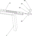
Fig. 1 is a schematic perspective view of the present invention.
Fig. 2 is a schematic perspective view of a grooving mechanism according to the present invention.
Fig. 3 is a schematic perspective view of the pushing mechanism of the present invention.
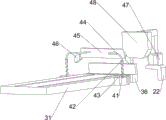
Fig. 4 is a schematic perspective view of the clamping mechanism of the present invention.
Fig. 5 is a schematic perspective view of the blanking mechanism of the present invention.
Fig. 6 is a schematic perspective view of the chip blowing mechanism of the present invention.
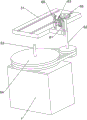
Fig. 7 is a schematic perspective view of a material shaking mechanism according to the present invention.
In the reference symbols: 1. the device comprises a base, 2, a grooving mechanism, 21, an air cylinder, 22, a support frame, 23, a motor, 24, a first rotating shaft, 25, a grooving cutter, 3, a pushing mechanism, 31, a workbench, 32, a first telescopic rod, 33, a push plate, 34, a first spring, 35, a connecting block, 36, a top plate, 4, a clamping mechanism, 41, a second telescopic rod, 42, a sliding sleeve, 43, a second spring, 44, a first connecting rod, 45, a press plate, 46, a wedge-shaped clamp plate, 47, a second connecting rod, 48, a first wedge-shaped block, 5, a blanking mechanism, 51, a third connecting rod, 52, a third telescopic rod, 53, a second rotating shaft, 54, a rack assembly, 55, a fourth telescopic rod, 56, a second wedge-shaped block, 57, a third spring, 6, a scrap blowing mechanism, 61, a bearing seat, 62, a third rotating shaft, 63, a fourth rotating shaft, 64, a transmission assembly, 65, a bevel gear set, 66, a fan, 7, a, The material shaking mechanism comprises a 71, a fourth connecting rod, 72, a pushing block, 73, a collecting box, 74, a third wedge block, 75, a fixing plate, 76, a fifth telescopic rod, 77 and a fourth spring.
Detailed Description
The above-described scheme is further illustrated below with reference to specific examples. It should be understood that these examples are for illustrative purposes and are not intended to limit the scope of the present application. The conditions used in the examples may be further adjusted according to the conditions of the particular manufacturer, and the conditions not specified are generally the conditions in routine experiments.
Example 1
A slotting device for square wood blocks for building materials is shown in figure 1 and comprises a base 1, a slotting mechanism 2 and a material pushing mechanism 3, wherein the slotting mechanism 2 is arranged on the left side of the upper front portion of the base 1, and the material pushing mechanism 3 is arranged on the rear side of the upper right portion of the base 1.
When people want to slot the square wood, the slotting equipment for the square wood blocks for the building materials can be used, firstly, a user places the square wood blocks in the pushing mechanism 3, the pushing mechanism 3 pushes the square wood blocks to the position of the slotting mechanism 2, and the slotting mechanism 2 slots the square wood blocks, so that the slotting effect is realized.
Example 2
On the basis of embodiment 1, as shown in fig. 2 and 3, the grooving mechanism 2 includes a cylinder 21, a support frame 22, a motor 23, a first rotating shaft 24 and a grooving cutter 25, the cylinder 21 is mounted on the base 1, the support frame 22 is connected to an output end of the cylinder 21, the motor 23 is mounted on a top of the support frame 22, the first rotating shaft 24 is connected to an output shaft of the motor 23, and the grooving cutter 25 is disposed at a rear end of the first rotating shaft 24.
The user opens cylinder 21, and cylinder 21 telescopic link extends right to promote support frame 22 and move right, and then drive motor 23 and move right, user's starter motor 23, motor 23 output shaft drive first pivot 24 and rotate, thereby drive grooving cutter 25 and rotate, grooving cutter 25 slots the square billet, realize grooved effect, turn off cylinder 21 and motor 23 when need not to slot, above action all stops.
Pushing equipment 3 is including workstation 31, first telescopic link 32, push pedal 33, first spring 34, connecting block 35 and roof 36, base 1 goes up the right side rear portion and is equipped with workstation 31, the workstation 31 top left and right sides all is equipped with first telescopic link 32, be equipped with push pedal 33 between two first telescopic link 32 front ends, push pedal 33 and workstation 31 sliding type connection, around having first spring 34 on the first telescopic link 32, first spring 34 front end is connected with push pedal 33, workstation 31 right side front portion is equipped with connecting block 35, connecting block 35 front side top is equipped with roof 36.
The user promotes push pedal 33 backward, and first spring 34 is compressed to drive first telescopic link 32 shrink, place the square billet on workstation 31 front side again, the user releases push pedal 33, and first spring 34 resets, thereby drives first telescopic link 32 extension, and then drives push pedal 33 and move forward, presss from both sides tightly the square billet, realizes pushing away the material effect.
Example 3
On the basis of embodiment 2, as shown in fig. 4 to 7, the device further comprises a clamping mechanism 4, the top of the workbench 31 is provided with the clamping mechanism 4, the clamping mechanism 4 comprises second telescopic rods 41, sliding sleeves 42, second springs 43, first connecting rods 44, pressure plates 45, wedge-shaped clamping plates 46, second connecting rods 47 and first wedge blocks 48, two second telescopic rods 41 are respectively arranged at the left and right parts of the front side of the workbench 31, a sliding sleeve 42 is arranged at the middle part of each second telescopic rod 41, a second spring 43 is wound on each second telescopic rod 41, the bottom end of each second spring 43 is connected with the top of the workbench 31, the top end of each second spring 43 is connected with the bottom of the sliding sleeve 42, the top of each sliding sleeve 42 is provided with the first connecting rod 44, the pressure plates 45 are arranged between the top ends of the two first connecting rods 44, the left and right sides of the lower part of the pressure plates 45 are provided with the wedge-shaped clamping plates, the top of the rear side of the second connecting rod 47 is provided with a first wedge-shaped block 48, and the first wedge-shaped block 48 is matched with the wedge-shaped clamping plate 46.
Support frame 22 drives second connecting rod 47 and slides right, thereby drive first wedge 48 and slide right, first wedge 48 and the cooperation of wedge splint 46 contact, wedge splint 46 downstream, thereby drive clamp plate 45 downstream, and then drive first connecting rod 44 downstream, second spring 43 is compressed, second telescopic link 41 shrink, make clamp plate 45 contact square billet, realize pressing from both sides tight effect, when support frame 22 drives second connecting rod 47 and slides left, thereby drive first wedge 48 and slide left, second spring 43 resets, thereby drive second telescopic link 41 extension, and then drive clamp plate 45 rebound, realize the effect that resets.
Still including unloading mechanism 5, be equipped with unloading mechanism 5 on the base 1, unloading mechanism 5 is including third connecting rod 51, third telescopic link 52, second pivot 53, rack subassembly 54, fourth telescopic link 55, second wedge 56 and third spring 57, the right side rotary type is equipped with second pivot 53 on the base 1, support frame 22 left side lower part is equipped with third connecting rod 51, third connecting rod 51 lower part is equipped with third telescopic link 52, fourth telescopic link 35 internal sliding type is equipped with second wedge 56, second wedge 56 bottom all is equipped with fourth telescopic link 55, be equipped with rack subassembly 54 between second pivot 53 upper portion and the third telescopic link 52 right-hand member, it has third spring 57 to wind on the fourth telescopic link 55, third spring 57 top is connected with second wedge 56, third spring 57 bottom and rack subassembly 54 are connected.
Support frame 22 drives third connecting rod 51 and moves to the right, thereby drive third telescopic link 52 and move to the right, and then drive the preceding lateral part of rack subassembly 54 and move to the right, rack subassembly 54 drives second pivot 53 and rotates, thereby drive the rear lateral part of rack subassembly 54 and move to the left, and then drive two fourth telescopic links 55 and move to the left, two fourth telescopic links 55 drive second wedge 56 and slide to the left, promote grooved square billet left, realize the unloading effect, when third connecting rod 51 moves to the left, third telescopic link 52 moves to the left, thereby drive the preceding lateral part of rack subassembly 54 and move to the left, and then drive second pivot 53 and rotate, make the rear lateral part of rack subassembly 54 move to the right, thereby drive two fourth telescopic links 55 and move to the right, and then drive second wedge 56 and move to the right.
Still including blowing bits mechanism 6, be equipped with on the base 1 and blow bits mechanism 6, blow bits mechanism 6 including the bearing frame 61, third pivot 62, fourth pivot 63, drive assembly 64, bevel gear group 65 and fan 66, bearing frame 61 is installed on workstation 31 top right side, base 1 left side rear portion rotary type is equipped with third pivot 62, be connected with drive assembly 64 between second pivot 53 and the third pivot 62, bearing frame 61 upper portion rotary type is equipped with fourth pivot 63, fourth pivot 63 left end is equipped with fan 66, be equipped with bevel gear group 65 between fourth pivot 63 and the third pivot 62.
The second shaft 53 drives the transmission assembly 64 to rotate, so as to drive the third shaft 62 to rotate, further drive the bevel gear set 65 to rotate, and the bevel gear set 65 drives the fourth shaft 63 to rotate, so as to drive the fan 66 to rotate, so that the wood chips generated during grooving are blown away, and the effect of blowing the wood chips is achieved.
Still including shaking material mechanism 7, be equipped with on the base 1 and shake material mechanism 7, shake material mechanism 7 including fourth connecting rod 71, ejector pad 72, collecting box 73, third wedge 74, fixed plate 75, fifth telescopic link 76 and fourth spring 77, the left part front side is equipped with collecting box 73 on the base 1, collecting box 73 front side upper portion slidingtype is equipped with ejector pad 72, the ejector pad 72 top is equipped with fourth connecting rod 71, fourth connecting rod 71 is connected with rack assembly 54, collecting box 73 front side upper portion is equipped with third wedge 74, the front side is equipped with two fixed plates 75 on the base 1, all be connected with fifth telescopic link 76 between every fixed plate 75 middle part and the collecting box 73, all around having fourth spring 77 on every fifth telescopic link 76, fourth spring 77 front end is connected with fixed plate 75, fourth spring 77 rear end is connected with collecting box 73.
Rack assembly 54 drives fourth connecting rod 71 and slides to the right, fourth connecting rod 71 drives ejector pad 72 and moves to the right, ejector pad 72 and the cooperation of third wedge 74 contact, third wedge 74 moves backward, fourth spring 77 extends, fifth telescopic link 76 extends backward, thereby drive collecting box 73 and slide backward, square billet drops to in the collecting box 73, realize the collection effect, when fourth connecting rod 71 moves left, ejector pad 72 moves left and keeps away from third wedge 74, fourth spring 77 resets and drives third wedge 74 forward motion, fifth telescopic link 76 shortens forward, thereby drive collecting box 73 forward motion, so relapse, the realization is with the even effect of billet shake.
The technical principle of the embodiment of the present invention is described above in conjunction with the specific embodiments. The description is only intended to explain the principles of embodiments of the invention and should not be taken in any way as limiting the scope of the embodiments of the invention. Based on the explanations herein, those skilled in the art will be able to conceive of other embodiments of the present invention without inventive step, and these embodiments will fall within the scope of the present invention.