CN219191485U - Plastic film composite bag processing is with flat-top machine - Google Patents
Plastic film composite bag processing is with flat-top machine Download PDFInfo
- Publication number
- CN219191485U CN219191485U CN202222575763.1U CN202222575763U CN219191485U CN 219191485 U CN219191485 U CN 219191485U CN 202222575763 U CN202222575763 U CN 202222575763U CN 219191485 U CN219191485 U CN 219191485U
- Authority
- CN
- China
- Prior art keywords
- plastic film
- fixedly connected
- film composite
- workbench
- plate
- Prior art date
- Legal status (The legal status is an assumption and is not a legal conclusion. Google has not performed a legal analysis and makes no representation as to the accuracy of the status listed.)
- Active
Links
Images


Classifications
-
- Y—GENERAL TAGGING OF NEW TECHNOLOGICAL DEVELOPMENTS; GENERAL TAGGING OF CROSS-SECTIONAL TECHNOLOGIES SPANNING OVER SEVERAL SECTIONS OF THE IPC; TECHNICAL SUBJECTS COVERED BY FORMER USPC CROSS-REFERENCE ART COLLECTIONS [XRACs] AND DIGESTS
- Y02—TECHNOLOGIES OR APPLICATIONS FOR MITIGATION OR ADAPTATION AGAINST CLIMATE CHANGE
- Y02W—CLIMATE CHANGE MITIGATION TECHNOLOGIES RELATED TO WASTEWATER TREATMENT OR WASTE MANAGEMENT
- Y02W30/00—Technologies for solid waste management
- Y02W30/50—Reuse, recycling or recovery technologies
- Y02W30/62—Plastics recycling; Rubber recycling
Abstract
The utility model relates to the field of plastic film composite bag processing, in particular to a flattening machine for plastic film composite bag processing. The technical scheme comprises the following steps: the plastic film composite bag cleaning device comprises a workbench, wherein one side of the surface of the workbench is provided with a fixed limiting mechanism for pressing and fixing the plastic film composite bag, and the other side of the surface of the workbench is provided with a cleaning mechanism for cleaning leftover materials generated by processing the plastic film composite bag. The pressing plate and the pressing plate are respectively driven to move downwards through the first air cylinder and the second air cylinder, so that the cut plastic film composite bag is conveniently pressed and fixed, the stability of the cutting process is improved, the cutting process is prevented from being deviated, the U-shaped supporting plate is conveniently horizontally moved through the T-shaped sliding block and the T-shaped sliding groove in sliding connection, and the plastic film composite bag is prevented from being normally placed on the surface of the workbench.
Description
Technical Field
The utility model relates to the field of plastic film composite bag processing, in particular to a flattening machine for plastic film composite bag processing.
Background
In the processing process of the plastic film composite bag, the corners of the plastic film composite bag are required to be cut through a flattening machine, so that the flatness of the corners is improved, and the quality and the attractiveness of the processed plastic film composite bag are improved.
Most of the existing flattening machines for processing plastic film composite bags are inconvenient to press and fix the stacked plastic film composite bags when cutting corners of the stacked plastic film composite bags, and easily cause the plastic film composite bags to deviate during cutting, so that the cutting accuracy is affected; and after cutting, the leftover materials of the plastic film composite bag are easily accumulated on the surface of the workbench, and the leftover materials are required to be cleaned manually, so that the labor force consumption is increased.
Disclosure of Invention
Aiming at the problems in the background technology, the utility model provides a flattening machine for processing plastic film composite bags, which is convenient for fixing the cut plastic film composite bags, improving the stability and cleaning and collecting the produced scraps.
The technical scheme of the utility model is as follows: a flattening machine for processing plastic film composite bags, comprising: the plastic film composite bag cleaning device comprises a workbench, wherein a fixed limiting mechanism used for pressing and fixing the plastic film composite bag is arranged on one side of the surface of the workbench, and a cleaning mechanism used for cleaning leftover materials generated by processing the plastic film composite bag is arranged on the other side of the surface of the workbench.
Preferably, fixed stop gear includes two U-shaped backup pads, two equal fixedly connected with cylinder No. one in the U-shaped backup pad, no. one equal fixedly connected with clamp plate in cylinder bottom, no. one clamp plate both ends all with a corresponding U-shaped backup pad inside wall sliding connection, workstation surface is located fixed stop gear one side both ends equal fixedly connected with fixed plate, two the level is equipped with the screw rod in the middle of the fixed plate, the thread bush is equipped with the drive block on the screw rod, drive block bottom fixedly connected with mounting panel, mounting panel bottom surface fixedly connected with motor No. one, no. one motor output dismantles and is connected with flat-mouth cutting knife, one of them fixed plate is kept away from screw rod one end fixedly connected with motor No. two, screw rod one end runs through one of them fixed plate and No. two motor output fixedly connected with, the screw rod other end is connected with another fixed plate lateral wall rotation, two equal fixedly connected with limiting plate in both sides limiting plate both ends respectively, flat-mouth cutting is kept away from fixed plate one side and is equipped with the drive block, no. two U-shaped backup pads are No. two bottom surfaces are connected with two inside diameter cutting blades, no. two motor output ends are connected with two cylinder fixedly connected with two inside diameter plates.
Preferably, two ends of the bottom of the first U-shaped supporting plate are fixedly connected with T-shaped sliding blocks, two sides of the surface of the workbench are fixedly connected with T-shaped sliding rails at the opposite positions of the T-shaped sliding blocks, and the T-shaped sliding blocks are in sliding connection with the corresponding T-shaped sliding rails.
Preferably, an extension groove is formed in the surface of the workbench below the flat-mouth cutting knife.
Preferably, the cleaning mechanism comprises a cleaning plate, the cleaning plate is located the workstation surface, cleaning plate one end is connected through the hinge rotation with workstation one side, no. two U-shaped backup pad bottom both ends all are connected with cleaning plate surface fixed, the workstation surface is located the equal fixedly connected with L shape backup pad in both sides of cleaning plate relative position, the top is connected with electric telescopic handle through the transfer block rotation in the L shape backup pad, electric telescopic handle bottom is connected through transfer block and cleaning plate surface rotation, workstation one side below is located cleaning plate relative position and is equipped with the collection box.
Preferably, one end of the bottom surface of the workbench is fixedly connected with a fixed block at the relative position of the collecting box, two sides of one end of the collecting box are horizontally and fixedly connected with inserting rods, one side of the fixed block is provided with inserting holes at the relative positions of the two inserting rods, and the inserting holes are in plug-in connection with the corresponding inserting rods.
Compared with the prior art, the utility model has the following beneficial technical effects: the first pressing plate and the second pressing plate are respectively driven to move downwards through the first air cylinder and the second air cylinder, so that the cut plastic film composite bag is conveniently pressed and fixed, the stability of the cutting process is improved, the deviation is avoided, the first U-shaped supporting plate is conveniently horizontally moved through the sliding connection of the T-shaped sliding block and the T-shaped sliding groove, and the situation that the plastic film composite bag is blocked by the first U-shaped supporting plate and normally placed on the surface of a workbench is avoided; the electric telescopic rod drives the cleaning plate to incline, so that leftover materials are conveniently guided into the collecting box to be cleaned and collected, and convenience in leftover material cleaning is improved.
Drawings
FIG. 1 shows a schematic view of a front cut-away structure of an embodiment of the present utility model;
FIG. 2 is a schematic diagram of a front view of an embodiment of the present utility model;
fig. 3 is a schematic view of a connection structure of a collecting box according to an embodiment of the present utility model.
Reference numerals: 1. a work table; 2. fixing a limiting mechanism; 3. a cleaning mechanism; 4. a T-shaped slide rail; 5. a first U-shaped supporting plate; 6. a first air cylinder; 7. a first pressing plate; 8. a T-shaped slider; 9. a fixing plate; 10. a motor I; 11. a flat-mouth cutting knife; 12. a mounting plate; 13. a driving block; 14. a screw; 15. a motor II; 16. a limiting plate; 17. an extension groove; 18. a second cylinder; 19. a second pressing plate; 20. a second U-shaped supporting plate; 21. a cleaning plate; 22. an L-shaped support plate; 23. an electric telescopic rod; 24. a collection box; 25. a fixed block; 26. a rod; 27. and a jack.
Detailed Description
The technical scheme of the utility model is further described below with reference to the attached drawings and specific embodiments.
Example 1
As shown in fig. 1 and 2, the flattening machine for processing plastic film composite bags provided by the utility model comprises: the plastic film composite bag cleaning machine comprises a workbench 1, a fixing limiting mechanism 2, a cleaning mechanism 3 and a cleaning mechanism, wherein the fixing limiting mechanism 2 is positioned on one side of the surface of the workbench 1 and used for pressing and fixing the plastic film composite bag, and the cleaning mechanism 3 is positioned on the other side of the surface of the workbench 1 and used for cleaning leftover materials generated by processing the plastic film composite bag.
The fixed limiting mechanism 2 comprises two U-shaped supporting plates 5, two first cylinders 6 are fixedly connected with the inner tops of the two first U-shaped supporting plates 5 respectively, a first pressing plate 7 is fixedly connected to the bottom of each first cylinder 6, two ends of each first pressing plate 7 are fixedly connected with the inner side walls of the corresponding first U-shaped supporting plates 5, two fixing plates 9 are fixedly connected to the surface of the workbench 1 at two ends of one side of the fixed limiting mechanism 2, a screw rod 14 is horizontally arranged between the two fixing plates 9, a driving block 13 is sleeved on the screw rod 14, a mounting plate 12 is fixedly connected to the bottom of the driving block 13, a first motor 10 is fixedly connected to the bottom surface of the mounting plate 12, a flat-mouth cutting knife 11 is detachably connected to the output end of the first motor 10, a second motor 15 is fixedly connected to one end of one fixing plate 9, one end of the screw rod 14 penetrates through one fixing plate 9 and the output end of the second motor 15, the other end of the screw rod 14 is rotationally connected with the side walls of the other fixing plate 9, two sides of the driving block 13 are fixedly connected with limiting plates 16, two ends of the two limiting plates 16 are fixedly connected with the side walls of the two fixing plates 9 respectively, two U-shaped supporting plates 20 are arranged in the bottom surface of the second fixing plate 20 and are fixedly connected to the inner side walls of the second motor 19, two side surfaces of the second motor 20 are fixedly connected to the flat-mouth cutting knife 18, and the two side surfaces of the second motor 19 are fixedly connected to the inner side of the flat-mouth cutting knife 18 is fixedly connected to the bottom of the second motor 19.
Two ends of the bottom of the U-shaped supporting plate 5 are fixedly connected with T-shaped sliding blocks 8, two T-shaped sliding rails 4 are fixedly connected to two sides of the surface of the workbench 1 and located at the opposite positions of the T-shaped sliding blocks 8, and the T-shaped sliding blocks 8 are in sliding connection with the corresponding T-shaped sliding rails 4.
An extension groove 17 is formed on the surface of the workbench 1 below the flat-mouth cutter 11.
The working principle based on the first embodiment is as follows: through T shape slider 8 and T shape slide rail 4 sliding connection, make two U-shaped backup pad 5 slide to being close to fixed plate 9 one side, then place the plastic film composite bag that stacks together that needs to cut in workstation 1 surface, and make its position that needs to cut be located extension groove 17 top, then slide U-shaped backup pad 5, make two clamp plates 7 all be located plastic film composite bag top, then drive clamp plate 7 downwardly moving through a cylinder 6, press the plastic film composite bag through clamp plate 7, improve the stability of its cutting in-process, simultaneously drive clamp plate 19 downwardly moving through No. two cylinders 18, press the plastic film composite bag, then start motor 10 and No. two motors 15, no. one motor 10 drives flat-mouth cutter 11 and rotates, no. two motors 15 drive screw rod 14 and rotate, make drive block 13 drive flat-mouth cutter 11 and carry out horizontal migration, cut the position that needs to cut to plastic film composite bag, can avoid flat-mouth cutter 11 to cause the damage to workstation 1 surface through extension groove 17.
Example two
As shown in fig. 1-3, based on the first embodiment, the utility model provides a flattening machine for processing plastic film composite bags, a cleaning mechanism 3 comprises a cleaning plate 21, the cleaning plate 21 is positioned on the surface of a workbench 1, one end of the cleaning plate 21 is rotatably connected with one side of the workbench 1 through a hinge, the surface of the cleaning plate 21 is fixedly connected with two ends of the bottom of a second U-shaped supporting plate 20, two L-shaped supporting plates 22 are fixedly connected with the surface of the workbench 1 and positioned on two sides of the opposite position of the cleaning plate 21, the top in the L-shaped supporting plates 22 is rotatably connected with an electric telescopic rod 23 through a conversion block, the bottom of the electric telescopic rod 23 is rotatably connected with the surface of the cleaning plate 21 through the conversion block, and a collecting box 24 is positioned below one side of the workbench 1 and positioned on the opposite position of the cleaning plate 21.
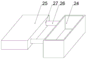
The fixed block 25 is fixedly connected to the bottom surface of the workbench 1, one end of the bottom surface is located at the opposite position of the collecting box 24, two inserting rods 26 are horizontally and fixedly connected to two sides of one end of the collecting box 24, two inserting holes 27 are formed in one side of the fixed block 25 and located at the opposite position of the two inserting rods 26, and the inserting holes 27 are in plug connection with the corresponding inserting rods 26.
The working principle based on the second embodiment is as follows: after the plastic film composite bag is cut, the cleaning plate 21 is driven to move through the electric telescopic rod 23, so that the cleaning plate is inclined, the second air cylinder 18 drives the second pressing plate 19 to ascend, leftover materials generated by cutting slide into the collecting box 24 through the inclined cleaning plate 21, convenience of leftover material cleaning is improved, the inserting rod 26 is pulled out of the inserting hole 27, the collecting box 24 is convenient to detach, and leftover materials in the collecting box are convenient to clean.
The above-described embodiments are merely a few preferred embodiments of the present utility model, and many alternative modifications and combinations of the above-described embodiments will be apparent to those skilled in the art based on the technical solutions of the present utility model and the related teachings of the above-described embodiments.
Claims (6)
1. A flattening machine for processing plastic film composite bags, comprising: workstation (1), its characterized in that: the plastic film composite bag cleaning device is characterized in that a fixed limiting mechanism (2) used for pressing and fixing the plastic film composite bag is arranged on one side of the surface of the workbench (1), and a cleaning mechanism (3) used for cleaning leftover materials generated by processing the plastic film composite bag is arranged on the other side of the surface of the workbench (1).
2. The flat-top machine for processing plastic film composite bags according to claim 1, wherein the fixed limiting mechanism (2) comprises two first U-shaped supporting plates (5), the top parts in the two first U-shaped supporting plates (5) are fixedly connected with first air cylinders (6), the bottoms of the first air cylinders (6) are fixedly connected with first pressing plates (7), two ends of the first pressing plates (7) are slidably connected with the inner side walls of the corresponding first U-shaped supporting plates (5), the surface of the workbench (1) is fixedly connected with fixing plates (9) at two ends of one side of the fixed limiting mechanism (2), screws (14) are horizontally arranged in the middle of the two fixing plates (9), driving blocks (13) are sleeved on the screws (14), the bottoms of the driving blocks (13) are fixedly connected with mounting plates (12), the bottoms of the mounting plates (12) are fixedly connected with first motors (10), the output ends of the first motors (10) are detachably connected with flat-top cutting blades (11), one end of the fixing plates (9) is far away from the corresponding first motors (14), two ends of the fixing plates (14) are fixedly connected with one end of the other end of each fixing plate (14) and fixedly connected with one end of the other end of each screw (14) which is fixedly connected with one end of the other (15), the utility model discloses a motor vehicle, including driving piece (13), fixed stop mechanism (2), flat-nose cutting sword (11), fixed stop mechanism (2), drive piece (13) both sides all sliding connection have limiting plate (16), two limiting plate (16) both ends respectively with two fixed plate (9) lateral wall fixed connection, flat-nose cutting sword (11) are kept away from fixed stop mechanism (2) one side and are equipped with No. two U-shaped backup pad (20), top fixedly connected with No. two cylinders (18) in No. two U-shaped backup pad (20), no. two cylinder (18) bottom surface fixedly connected with clamp plate (19) No. two, no. two clamp plate (19) both ends all with No. two U-shaped backup pad (20) inside wall sliding connection.
3. The flat-top machine for processing plastic film composite bags according to claim 2, wherein two ends of the bottom of the first U-shaped supporting plate (5) are fixedly connected with T-shaped sliding blocks (8), two sides of the surface of the workbench (1) are fixedly connected with T-shaped sliding rails (4) at the opposite positions of the T-shaped sliding blocks (8), and the T-shaped sliding blocks (8) are in sliding connection with the corresponding T-shaped sliding rails (4).
4. The flattening machine for processing plastic film composite bags according to claim 1, wherein an extension groove (17) is formed on the surface of the workbench (1) below the flat cutting knife (11).
5. The flat-top machine for processing plastic film composite bags according to claim 2, wherein the cleaning mechanism (3) comprises a cleaning plate (21), the cleaning plate (21) is located on the surface of the workbench (1), one end of the cleaning plate (21) is rotationally connected with one side of the workbench (1) through a hinge, two ends of the bottom of the U-shaped supporting plate (20) are fixedly connected with the surface of the cleaning plate (21), two sides of the surface of the workbench (1) located at the opposite positions of the cleaning plate (21) are fixedly connected with L-shaped supporting plates (22), the inner top of the L-shaped supporting plates (22) is rotationally connected with an electric telescopic rod (23) through a switching block, the bottom of the electric telescopic rod (23) is rotationally connected with the surface of the cleaning plate (21), and a collecting box (24) is arranged at the opposite positions of the cleaning plate (21) below one side of the workbench (1).
6. The plastic film composite bag processing flattening machine according to claim 5, wherein one end of the bottom surface of the workbench (1) is fixedly connected with a fixing block (25) at the opposite position of the collecting box (24), two sides of one end of the collecting box (24) are horizontally and fixedly connected with inserting rods (26), one side of the fixing block (25) is provided with inserting holes (27) at the opposite position of the two inserting rods (26), and the inserting holes (27) are in plug connection with the corresponding inserting rods (26).
Priority Applications (1)
| Application Number | Priority Date | Filing Date | Title |
|---|---|---|---|
| CN202222575763.1U CN219191485U (en) | 2022-09-28 | 2022-09-28 | Plastic film composite bag processing is with flat-top machine |
Applications Claiming Priority (1)
| Application Number | Priority Date | Filing Date | Title |
|---|---|---|---|
| CN202222575763.1U CN219191485U (en) | 2022-09-28 | 2022-09-28 | Plastic film composite bag processing is with flat-top machine |
Publications (1)
| Publication Number | Publication Date |
|---|---|
| CN219191485U true CN219191485U (en) | 2023-06-16 |
Family
ID=86706745
Family Applications (1)
| Application Number | Title | Priority Date | Filing Date |
|---|---|---|---|
| CN202222575763.1U Active CN219191485U (en) | 2022-09-28 | 2022-09-28 | Plastic film composite bag processing is with flat-top machine |
Country Status (1)
| Country | Link |
|---|---|
| CN (1) | CN219191485U (en) |
-
2022
- 2022-09-28 CN CN202222575763.1U patent/CN219191485U/en active Active
Similar Documents
| Publication | Publication Date | Title |
|---|---|---|
| CN217290575U (en) | Novel numerical control planer type milling machine structure | |
| CN219191485U (en) | Plastic film composite bag processing is with flat-top machine | |
| CN218362690U (en) | Hardware fitting laser cutting device with garbage collection | |
| CN216040380U (en) | School clothes production is with cloth trimming device convenient to location | |
| CN215659222U (en) | Numerical control single-sided milling machine | |
| CN212497305U (en) | Grinding wheel cutting device with dust removal function | |
| CN213499450U (en) | Thermoplastic felt processing device convenient for controlling cutting size | |
| CN212371741U (en) | Waste recovery device of milling machine | |
| CN210849387U (en) | Lathe saw convenient to clean | |
| CN219336139U (en) | Special-shaped section bar cuts vanning equipment convenient to it is clean | |
| CN218284752U (en) | Waste cleaning device of milling machine for machining mechanical parts | |
| CN215469473U (en) | High-efficient touch panel processingequipment | |
| CN219521651U (en) | Cleaning device for guide rail of grinding machine | |
| CN217916981U (en) | A tailor frock for processing of environmental protection corrugated paper carton | |
| CN219665729U (en) | Operating table of machining center | |
| CN219787342U (en) | Ultra-large gantry drilling and milling integrated machine | |
| CN219902344U (en) | Grooving mechanism for production of fine denier middle-reinforced fiber paper tube | |
| CN219900494U (en) | Cutting machine for nut processing | |
| CN219445176U (en) | Paper cutting device | |
| CN215616463U (en) | Intelligent die engraving equipment | |
| CN219854892U (en) | Round pressing and cutting machine | |
| CN216966380U (en) | A adjustable turret type milling machine for blade production | |
| CN219358678U (en) | Workbench for processing aluminum-plastic doors and windows | |
| CN219379734U (en) | Milling machine elevating platform | |
| CN219632693U (en) | High-stability grooving machine |
Legal Events
| Date | Code | Title | Description |
|---|---|---|---|
| GR01 | Patent grant | ||
| GR01 | Patent grant |