CN112248245A - Automatic processing production method - Google Patents
Automatic processing production method Download PDFInfo
- Publication number
- CN112248245A CN112248245A CN202011082389.0A CN202011082389A CN112248245A CN 112248245 A CN112248245 A CN 112248245A CN 202011082389 A CN202011082389 A CN 202011082389A CN 112248245 A CN112248245 A CN 112248245A
- Authority
- CN
- China
- Prior art keywords
- loading
- production
- production equipment
- processed
- feeding
- Prior art date
- Legal status (The legal status is an assumption and is not a legal conclusion. Google has not performed a legal analysis and makes no representation as to the accuracy of the status listed.)
- Granted
Links
Images

Classifications
-
- B—PERFORMING OPERATIONS; TRANSPORTING
- B28—WORKING CEMENT, CLAY, OR STONE
- B28D—WORKING STONE OR STONE-LIKE MATERIALS
- B28D1/00—Working stone or stone-like materials, e.g. brick, concrete or glass, not provided for elsewhere; Machines, devices, tools therefor
-
- B—PERFORMING OPERATIONS; TRANSPORTING
- B28—WORKING CEMENT, CLAY, OR STONE
- B28D—WORKING STONE OR STONE-LIKE MATERIALS
- B28D7/00—Accessories specially adapted for use with machines or devices of the preceding groups
-
- B—PERFORMING OPERATIONS; TRANSPORTING
- B28—WORKING CEMENT, CLAY, OR STONE
- B28D—WORKING STONE OR STONE-LIKE MATERIALS
- B28D7/00—Accessories specially adapted for use with machines or devices of the preceding groups
- B28D7/005—Devices for the automatic drive or the program control of the machines
-
- B—PERFORMING OPERATIONS; TRANSPORTING
- B28—WORKING CEMENT, CLAY, OR STONE
- B28D—WORKING STONE OR STONE-LIKE MATERIALS
- B28D7/00—Accessories specially adapted for use with machines or devices of the preceding groups
- B28D7/04—Accessories specially adapted for use with machines or devices of the preceding groups for supporting or holding work or conveying or discharging work
Abstract
The invention discloses an automatic processing production method, which comprises the following steps: (1) the first feeding and discharging mechanical arm transfers the workpieces to be processed at the first material frame to a workbench of first production equipment, the second feeding and discharging mechanical arm transfers the workpieces to be processed at the second material frame to a workbench of second production equipment, and the first production equipment and the second production equipment automatically process the workpieces to be processed on the respective workbench; and (2) the first loading and unloading mechanical arm transfers the workpiece to be processed at the first material frame to the workbench of the first production equipment again, and simultaneously the second loading and unloading mechanical arm takes away the processed workpiece on the workbench of the first production equipment; similarly, the second loading and unloading mechanical arm transfers the workpiece to be processed at the second material frame to the workbench of the second production equipment again, and simultaneously the first loading and unloading mechanical arm takes away the processed workpiece on the workbench of the second production equipment; thereby shortening the working hours of loading and unloading and improving the processing efficiency.
Description
Technical Field
The invention relates to the field of machining, in particular to an automatic machining production method suitable for automatically machining workpieces, especially glass workpieces.
Background
With the continuous development of economy and the continuous progress of society, various material consumer goods are provided for the life of people, and electronic equipment is one of the material consumer goods.
As is well known, smart phones, smart watches, vehicle navigation devices, tablet computers, notebook computers, and the like belong to electronic devices; in electronic devices, various screens are used, for example, a touch screen and a non-touch screen.
In the case of a touch screen or a non-touch screen, the material of the touch screen or the non-touch screen is generally glass, so that various processing of the glass, such as, but not limited to, engraving and milling, cannot be avoided in the manufacturing process of the touch screen or the non-touch screen.
The existing production line for automatically processing glass generally comprises two or more sets of units which are independent from each other, wherein each set of unit generally comprises production equipment, a material frame positioned beside the production equipment and a feeding and discharging manipulator responsible for feeding and discharging; because the feeding and discharging manipulator of each set of unit is only responsible for the feeding and discharging operation in the set of unit in the feeding and discharging process, the feeding and discharging manipulator of the production line has the working time of feeding and discharging, thereby causing the defect of low efficiency.
Of course, the above-mentioned drawbacks are also present in the production methods of other production lines than the automatic processing of glass, such as but not limited to the mobile phone middle plate or the mobile phone middle frame.
Therefore, it is necessary to provide an automatic processing method for improving the processing efficiency and reducing the loading/unloading time to overcome the above-mentioned drawbacks.
Disclosure of Invention
The invention aims to provide an automatic processing production method which improves the processing efficiency and shortens the loading and unloading working hours.
In order to achieve the purpose, the invention provides an automatic processing production method of an automatic processing production line. Wherein, automatic processing production line contain first production facility, with first production facility side by side and spaced apart second production facility, be located the first material frame of first production facility's side, be located the second material frame of second production facility's side, follow the side by side direction of first production facility and second production facility span in the crossbeam of both tops of first production facility and second production facility, assemble in the first last unloading manipulator of crossbeam and assemble in the second last unloading manipulator of crossbeam. The automatic processing production method of the invention comprises the following steps: (1) the first feeding and discharging mechanical arm transfers the workpieces to be processed at the first material frame to a workbench of first production equipment, the second feeding and discharging mechanical arm transfers the workpieces to be processed at the second material frame to a workbench of second production equipment, and the first production equipment and the second production equipment automatically process the workpieces to be processed on the respective workbench; and (2) the first loading and unloading mechanical arm transfers the workpiece to be processed at the first material frame to the workbench of the first production equipment again, and simultaneously the second loading and unloading mechanical arm takes away the processed workpiece on the workbench of the first production equipment; similarly, the second loading and unloading manipulator transfers the workpiece to be processed at the second material frame to the workbench of the second production equipment, and simultaneously the first loading and unloading manipulator takes away the processed workpiece on the workbench of the second production equipment.
Preferably, in the step (2), the first feeding and discharging mechanical arm and the second feeding and discharging mechanical arm transfer the taken-away processed workpiece to an external conveying line which is located right below the cross beam and in a side-by-side space between the first production equipment and the second production equipment, and the external conveying line conveys the processed workpiece outwards in a production line.
Preferably, in the step (2), while the first loading and unloading manipulator slides to the workbench of the first production equipment, the second loading and unloading manipulator slides to the external conveying line, the first loading manipulator places the workpiece to be processed taken from the first material frame on the workbench of the first production equipment, and the second loading and unloading manipulator places the processed workpiece taken from the workbench of the first production equipment on the external conveying line.
Preferably, in the step (2), while the second feeding and discharging manipulator slides to the workbench of the second production equipment, the first feeding and discharging manipulator slides to the external conveying line, the second feeding manipulator places the workpiece to be processed taken from the second material frame on the workbench of the second production equipment, and the first feeding and discharging manipulator places the processed workpiece taken from the workbench of the second production equipment on the external conveying line.
Preferably, the direction of the external conveying line for conveying the processed workpiece is perpendicular to the sliding direction of the first loading and unloading manipulator.
Preferably, in the step (2), while the first loading and unloading manipulator slides to the first material frame, the second loading and unloading manipulator slides to the workbench of the first production equipment.
Preferably, in the step (2), the second feeding and discharging manipulator slides to the second material frame, and the first feeding and discharging manipulator slides to the workbench of the second production equipment.
Preferably, in the step (1), the first loading and unloading robot slides to the parallel space between the first production equipment and the second production equipment after transferring the workpiece to be processed of the first frame to the workbench of the first production equipment; the second feeding and discharging mechanical arm transfers the workpiece to be processed of the second material frame to the workbench of the second production equipment and then slides to the parallel space between the first production equipment and the second production equipment.
Preferably, the first feeding and discharging manipulator, the second feeding and discharging manipulator, the first production equipment, the second production equipment and the external conveying line work in a coordinated manner under the control of a controller.
Preferably, the first material frame and the second material frame can slide along the direction crossing the cross beam.
Compared with the prior art, the first feeding and discharging mechanical arm transfers the workpiece to be processed at the first material frame to the workbench of the first production equipment again, and the second feeding and discharging mechanical arm takes away the processed workpiece on the workbench of the first production equipment; similarly, the second loading and unloading mechanical arm transfers the workpiece to be processed at the second material frame to the workbench of the second production equipment again, and simultaneously the first loading and unloading mechanical arm takes away the processed workpiece on the workbench of the second production equipment; therefore, the phenomenon that the feeding and discharging working hours are too long due to the fact that the same feeding and discharging mechanical arm firstly performs feeding and then performs discharging can be avoided, and therefore the automatic processing production method can shorten the feeding and discharging working hours and improve the processing efficiency.
Drawings
FIG. 1 is a flow chart of the automated manufacturing process of the present invention.
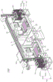
FIG. 2 is a schematic perspective view of an automatic processing line for carrying out the automatic processing method of the present invention.
Detailed Description
Embodiments of the present invention will now be described with reference to the drawings, wherein like element numerals represent like elements.
Referring to fig. 2, the automatic processing line 100 implementing the automatic processing method of the present invention is preferably electrically connected to a conventional controller 200, so as to improve the automation level of the automatic processing line 100 by means of the controller 200. The automatic processing production line 100 includes a first production apparatus 10, a second production apparatus 20, a first material frame 30, a second material frame 40, a first loading and unloading manipulator 50, a second loading and unloading manipulator 60, a cross beam 70 and an external connection conveying line 80. The first production equipment 10 and the second production equipment 20 are arranged side by side in a spaced-apart manner, preferably, the first production equipment 10 and the second production equipment 20 are also aligned with each other, so that the layout of the two is more reasonable and compact, but not limited to; the cross beam 70 crosses over both the first production equipment 10 and the second production equipment 20 along the side-by-side direction of the first production equipment 10 and the second production equipment 20 (i.e. the direction indicated by the arrow a and the opposite direction), preferably, the cross beam 70 is suspended right above both the first production equipment 10 and the second production equipment 20 by a bipod 71, and the bipod 71 is positioned in the side-by-side space 21 between the first production equipment 10 and the second production equipment 20, so as to ensure the structural compactness and rationality, but not limited thereto; the first material frame 30 is located beside the first production apparatus 10, such as but not limited to the left side of the first production apparatus 10 shown in fig. 2; the second frame 40 is located beside the second production apparatus 20, such as but not limited to the right side of the second production apparatus 20 shown in fig. 2; the external connection conveying line 80 is located in the parallel space 21 between the first production equipment 10 and the second production equipment 20, the external connection conveying line 80 is also located right below the cross beam 70, preferably, when the cross beam 70 is suspended right above the first production equipment 10 and the second production equipment 20 through the bipod 71, the external connection conveying line 80 is also located between the bipod 71, and the state is shown in fig. 2; the first loading and unloading robot 50 is mounted to the beam 70 and the second loading and unloading robot 60 is mounted to the beam 70. Specifically, the first material frame 30, the first production equipment 10, the second production equipment 20 and the second material frame 40 are sequentially arranged in an aligned manner along a parallel direction of the first production equipment 10 and the second production equipment 20, so that the automatic processing production line 100 is more compact and reasonable in structure and occupies a smaller space. It should be noted that, when the work pieces after being discharged are not required to be conveyed to a subsequent assembly line, the external conveying line 80 may be omitted, and the discharged work pieces may be stored in batches by using the collecting container. More specifically, the following:
as shown in fig. 2, the first loading and unloading robot 50 and the second loading and unloading robot 60 are respectively slidably disposed on the cross beam 70 along a parallel direction of the first production equipment 10 and the second production equipment 20, so that the first loading and unloading robot 50 and the second loading and unloading robot 60 can respectively slide on the cross beam 70. Because the first feeding and discharging manipulator 50 and the second feeding and discharging manipulator 60 can automatically slide on the cross beam 70, at this time, the first feeding and discharging manipulator 50 and the second feeding and discharging manipulator 60 can be respectively provided with a traveling mechanism which travels on the cross beam 70, the traveling mechanism mainly comprises a servo motor and a traveling gear, for example, and the cross beam 70 is correspondingly provided with a traveling rack which is meshed with the traveling gear; of course, according to actual needs, the first loading and unloading robot 50 and the second loading and unloading robot 60 can also achieve the purpose of automatic sliding through belt transmission, chain transmission or screw-nut transmission, and the structures and the assembly relations thereof are well known in the art, and therefore are not described herein again.
As shown in fig. 2, the external connection conveying line 80 is a belt conveying line, and is, of course, a chain conveying line according to actual needs; meanwhile, the first production equipment 10 and the second production equipment 20 are each numerically controlled machine tools, and of course, other machine tools than the numerically controlled machine tools are selected according to actual needs. Furthermore, one end of the cross beam 70 extends to the position right above the first material frame 30, and the other end of the cross beam 70 extends to the position right above the second material frame 40, so as to meet the requirement of the sliding stroke of the first feeding and discharging manipulator 50 and the second feeding and discharging manipulator 60 on the cross beam 70. In order to enable the first material frame 30 and the second material frame 40 to be transported in a sliding manner, material frame transport lines 90 are respectively arranged at the bottoms of the first material frame 30 and the second material frame 40, and each material frame transport line 90 comprises a material frame 91 and a transport mechanism 92 assembled at the material frame 91; specifically, the conveying mechanism 92 includes a supporting slide 92a slidably disposed on the top of the material frame 91 and a belt transmission mechanism 92b for driving the supporting slide 92a to slide along the direction crossing the side-by-side direction, so as to drive the supporting slide 92a together with the first material frame 30 or the second material frame 40 on the supporting slide 92a to slide along the direction crossing the side-by-side direction (such as, but not limited to, a direction perpendicular to the side-by-side direction) by means of the belt transmission mechanism 92 b; preferably, the supporting slide 92a is provided with a positioning and clamping device 93 for positioning and clamping the first material frame 30 or the second material frame 40, and preferably, the supporting slide 92a can position and clamp two first material frames 30 or second material frames 40 in a direction parallel to the side-by-side direction, but not limited thereto. It will be appreciated that the belt drive 92b in the conveyor 92 can be replaced by a chain drive or a lead screw nut, as desired.
Therefore, with reference to fig. 1, the automatic processing method of the present invention comprises the following steps:
s001, the first loading/unloading robot 50 transfers the workpiece to be processed at the first material frame 30 to the table 11 of the first production facility 10, the second loading/unloading robot 60 transfers the workpiece to be processed at the second material frame 40 to the table 21 of the second production facility 20, and the workpieces to be processed on the respective tables 11, 21 are automatically processed by the first production facility 10 and the second production facility 20. Specifically, in step S001, the first loading/unloading robot 50 transfers the workpiece to be processed of the first frame 30 onto the table 11 of the first production facility 10, and then slides into the parallel space 21 between the first production facility 10 and the second production facility 20; the second loading/unloading robot 60 transfers the work pieces to be processed of the second frame 40 to the table 21 of the second manufacturing facility 20 and then slides into the parallel space 21 between the first manufacturing facility 10 and the second manufacturing facility 20, thereby further reducing the loading/unloading man-hour. And
s002, the first loading and unloading mechanical arm 50 transfers the workpiece to be processed at the first material frame 30 to the workbench 11 of the first production equipment 10 again, and meanwhile, the second loading and unloading mechanical arm 60 takes away the processed workpiece on the workbench 11 of the first production equipment 10; similarly, the second loading/unloading robot 60 transfers the workpiece to be processed at the second material frame 40 to the table 21 of the second production facility 20 again, and the first loading/unloading robot 50 removes the processed workpiece from the table 21 of the second production facility 20. Specifically, in step S002, the first feeding and discharging robot 50 and the second feeding and discharging robot 60 transfer the taken-away processed workpiece to the external conveyor line 80, and the external conveyor line 80 conveys the processed workpiece to the outside in a flow line, preferably, the direction of conveying the processed workpiece by the external conveyor line 80 is perpendicular to the sliding direction of the first feeding and discharging robot 50, so as to further improve the purpose of streamlined production. More specifically, in step S002, while the first loading and unloading robot 50 slides to the table 11 of the first production apparatus 10, the second loading and unloading robot 60 slides to the external connection conveyor line 80, the first loading and unloading robot 50 places the workpiece to be processed taken from the first material frame 30 on the table 11 of the first production apparatus 10, and the second loading and unloading robot 60 places the processed workpiece taken from the table 11 of the first production apparatus 10 on the external connection conveyor line 80; similarly, in step S002, while the second feeding and discharging manipulator 60 slides to the workbench 21 of the second production equipment 20, the first feeding and discharging manipulator 50 slides to the external connection conveyor line 80, the second feeding and discharging manipulator 60 places the workpiece to be processed taken from the second material frame 40 on the workbench 21 of the second production equipment 20, and the first feeding and discharging manipulator 50 places the processed workpiece taken from the workbench 21 of the second production equipment 20 on the external connection conveyor line 80. In addition, in step S002, while the first loading and unloading robot 50 slides to the first material frame 30, the second loading and unloading robot 60 slides to the working table 11 of the first production equipment 10; the second loading/unloading robot 60 slides to the second material frame 40 and the first loading/unloading robot 50 slides to the worktable 21 of the second manufacturing apparatus 20, so the invention is not limited thereto. It should be noted that, in order to further improve the coordination and the automation degree, the first feeding and discharging manipulator 50, the second feeding and discharging manipulator 60, the first production equipment 10, the second production equipment 20 and the external connection conveying line 80 coordinate to work under the control of a controller 200; in addition, the first material frame 30 and the second material frame 40 can slide along the direction crossing the cross beam 70, so as to be more beneficial to the grabbing operation of the first feeding and discharging mechanical arm 50 and the second feeding and discharging mechanical arm 60 during feeding.
Compared with the prior art, the first loading and unloading manipulator 50 transfers the workpiece to be processed at the first material frame 30 to the workbench 11 of the first production equipment 10 again, and the second loading and unloading manipulator 60 takes away the processed workpiece on the workbench 11 of the first production equipment 10; similarly, the second loading and unloading robot 60 transfers the workpiece to be processed at the second material frame 40 to the workbench 21 of the second production equipment 20 again, and simultaneously the first loading and unloading robot 50 takes away the processed workpiece on the workbench 21 of the second production equipment 20; therefore, the phenomenon that the feeding and discharging working hours are too long due to the fact that the same feeding and discharging mechanical arm firstly performs feeding and then performs discharging can be avoided, and therefore the automatic processing production method can shorten the feeding and discharging working hours and improve the processing efficiency.
The above disclosure is only for the purpose of illustrating the preferred embodiments of the present invention and is not to be construed as limiting the scope of the present invention, therefore, the present invention is not limited by the appended claims.
Claims (10)
1. An automatic processing production method of an automatic processing production line, the automatic processing production line comprises a first production device, a second production device which is arranged side by side and spaced apart from the first production device, a first material frame which is arranged beside the first production device, a second material frame which is arranged beside the second production device, a cross beam which stretches across the first production device and the second production device along the side by side direction of the first production device and the second production device, a first feeding and discharging mechanical arm which is assembled on the cross beam and a second feeding and discharging mechanical arm which is assembled on the cross beam, and the automatic processing production method is characterized by comprising the following steps:
(1) the first feeding and discharging mechanical arm transfers the workpieces to be processed at the first material frame to a workbench of first production equipment, the second feeding and discharging mechanical arm transfers the workpieces to be processed at the second material frame to a workbench of second production equipment, and the first production equipment and the second production equipment automatically process the workpieces to be processed on the respective workbench; and
(2) the first feeding and discharging mechanical arm transfers the workpiece to be processed at the first material frame to the workbench of the first production equipment again, and the second feeding and discharging mechanical arm takes away the processed workpiece on the workbench of the first production equipment; similarly, the second loading and unloading manipulator transfers the workpiece to be processed at the second material frame to the workbench of the second production equipment, and simultaneously the first loading and unloading manipulator takes away the processed workpiece on the workbench of the second production equipment.
2. The automated processing and production method according to claim 1, wherein in the step (2), the first feeding and discharging robot and the second feeding and discharging robot transfer the taken processed workpiece to an external conveying line which is located right below the cross beam and in the parallel space between the first production equipment and the second production equipment, and the processed workpiece is conveyed outwards by the external conveying line in a production line.
3. The automated processing and manufacturing method according to claim 2, wherein in the step (2), the first loading and unloading robot slides to the table of the first manufacturing apparatus, the second loading and unloading robot slides to the external conveyor line, the first loading and unloading robot places the workpiece to be processed taken from the first frame on the table of the first manufacturing apparatus, and the second loading and unloading robot places the processed workpiece taken from the table of the first manufacturing apparatus on the external conveyor line.
4. The automatic processing and producing method according to claim 2, wherein in the step (2), the second loading and unloading robot slides to the table of the second producing device, the first loading and unloading robot slides to the external conveying line, the second loading and unloading robot places the workpiece to be processed taken from the second frame on the table of the second producing device, and the first loading and unloading robot places the processed workpiece taken from the table of the second producing device on the external conveying line.
5. The automatic processing and producing method of claim 2, wherein the direction of the external conveying line conveying the processed workpiece is perpendicular to the sliding direction of the first loading and unloading manipulator.
6. The automatic processing and production method according to claim 1, wherein in the step (2), the first loading and unloading manipulator slides to the first material frame, and the second loading and unloading manipulator slides to the workbench of the first production equipment.
7. The automatic processing and producing method of claim 1, wherein in the step (2), the second loading and unloading robot slides to the second material frame, and simultaneously, the first loading and unloading robot slides to the workbench of the second producing device.
8. The automated processing and manufacturing method according to claim 1, wherein in the step (1), the first loading/unloading robot slides to the side-by-side space between the first manufacturing apparatus and the second manufacturing apparatus after transferring the workpiece to be processed of the first frame to the work table of the first manufacturing apparatus; the second feeding and discharging mechanical arm transfers the workpiece to be processed of the second material frame to the workbench of the second production equipment and then slides to the parallel space between the first production equipment and the second production equipment.
9. The automatic processing and producing method of claim 2, wherein the first feeding and discharging robot, the second feeding and discharging robot, the first producing device, the second producing device and the external conveying line are coordinated under the control of a controller.
10. The automated processing production method according to claim 1, wherein the first material frame and the second material frame can slide in a direction crossing the cross beam.
Priority Applications (1)
| Application Number | Priority Date | Filing Date | Title |
|---|---|---|---|
| CN202011082389.0A CN112248245B (en) | 2020-10-10 | 2020-10-10 | Automatic processing production method |
Applications Claiming Priority (1)
| Application Number | Priority Date | Filing Date | Title |
|---|---|---|---|
| CN202011082389.0A CN112248245B (en) | 2020-10-10 | 2020-10-10 | Automatic processing production method |
Publications (2)
| Publication Number | Publication Date |
|---|---|
| CN112248245A true CN112248245A (en) | 2021-01-22 |
| CN112248245B CN112248245B (en) | 2022-12-13 |
Family
ID=74243028
Family Applications (1)
| Application Number | Title | Priority Date | Filing Date |
|---|---|---|---|
| CN202011082389.0A Active CN112248245B (en) | 2020-10-10 | 2020-10-10 | Automatic processing production method |
Country Status (1)
| Country | Link |
|---|---|
| CN (1) | CN112248245B (en) |
Cited By (1)
| Publication number | Priority date | Publication date | Assignee | Title |
|---|---|---|---|---|
| CN115870630A (en) * | 2023-03-01 | 2023-03-31 | 深圳市镭沃自动化科技有限公司 | Control method of laser etching equipment, laser etching equipment and computer readable storage medium |
Citations (6)
| Publication number | Priority date | Publication date | Assignee | Title |
|---|---|---|---|---|
| WO2003061899A1 (en) * | 2002-01-24 | 2003-07-31 | Ward John D | Auto feed system for compressed propellant tools and pressure compensating valve therefore |
| CN104354097A (en) * | 2014-10-20 | 2015-02-18 | 深圳市远洋翔瑞机械股份有限公司 | Automatic loading and unloading device for numerically-controlled machine tool |
| CN105438829A (en) * | 2014-08-21 | 2016-03-30 | 大族激光科技产业集团股份有限公司 | Automatic feeding and discharging device |
| CN109227293A (en) * | 2018-10-17 | 2019-01-18 | 宁波市江北欣盛数控机械有限公司 | A kind of automatic loading and unloading system of cross workpiece grinding machine |
| CN209851335U (en) * | 2019-04-25 | 2019-12-27 | 叶雨青 | Automatic feeding and discharging device for LCD |
| CN210756322U (en) * | 2019-09-11 | 2020-06-16 | 浙江畅尔智能装备股份有限公司 | Automatic production line for processing workpiece by using numerical control machine tool |
-
2020
- 2020-10-10 CN CN202011082389.0A patent/CN112248245B/en active Active
Patent Citations (6)
| Publication number | Priority date | Publication date | Assignee | Title |
|---|---|---|---|---|
| WO2003061899A1 (en) * | 2002-01-24 | 2003-07-31 | Ward John D | Auto feed system for compressed propellant tools and pressure compensating valve therefore |
| CN105438829A (en) * | 2014-08-21 | 2016-03-30 | 大族激光科技产业集团股份有限公司 | Automatic feeding and discharging device |
| CN104354097A (en) * | 2014-10-20 | 2015-02-18 | 深圳市远洋翔瑞机械股份有限公司 | Automatic loading and unloading device for numerically-controlled machine tool |
| CN109227293A (en) * | 2018-10-17 | 2019-01-18 | 宁波市江北欣盛数控机械有限公司 | A kind of automatic loading and unloading system of cross workpiece grinding machine |
| CN209851335U (en) * | 2019-04-25 | 2019-12-27 | 叶雨青 | Automatic feeding and discharging device for LCD |
| CN210756322U (en) * | 2019-09-11 | 2020-06-16 | 浙江畅尔智能装备股份有限公司 | Automatic production line for processing workpiece by using numerical control machine tool |
Cited By (1)
| Publication number | Priority date | Publication date | Assignee | Title |
|---|---|---|---|---|
| CN115870630A (en) * | 2023-03-01 | 2023-03-31 | 深圳市镭沃自动化科技有限公司 | Control method of laser etching equipment, laser etching equipment and computer readable storage medium |
Also Published As
| Publication number | Publication date |
|---|---|
| CN112248245B (en) | 2022-12-13 |
Similar Documents
| Publication | Publication Date | Title |
|---|---|---|
| US11571774B2 (en) | Intelligent plate parts machining production line combining universal and special equipment | |
| CN109175680B (en) | Full-automatic PCB ultraviolet laser cutting machine | |
| CN102699225B (en) | Loading and unloading manipulator for machining aluminum frame assembly | |
| CN108190462B (en) | Workpiece flexible transfer system with cache function | |
| CN207681800U (en) | Box-type substation robot automation's Flexible Welding Line | |
| KR20060132979A (en) | Workpiece machining method and workpiece machining device for a transfer system with machining carried out on a number of sides | |
| CN111843487B (en) | Intelligent material-increasing and material-decreasing composite manufacturing system | |
| CN112248245B (en) | Automatic processing production method | |
| CN108941617A (en) | A kind of manipulator and its production method | |
| CN105855997A (en) | Flexible production line control system and method | |
| CN219358163U (en) | Device for removing burrs of steering knuckle in automatic unit | |
| CN110977262B (en) | Welding method for automatic welding line of flexible engine room | |
| CN205926895U (en) | Unloading set composite on punch press unilateral compact | |
| CN115140479B (en) | Medium-sized material caching system and caching method | |
| CN208758627U (en) | A kind of manipulator and automatic production line | |
| CN108202964B (en) | Workpiece transfer system | |
| CN213617607U (en) | Automatic processing production line | |
| CN208801096U (en) | A kind of flange automatic feed/discharge system of processing | |
| CN217942380U (en) | Automatic dress of fork frame robot welds system | |
| CN108217119B (en) | Workpiece transfer system | |
| CN113751914B (en) | Automatic production line and production method for metal welding processing | |
| JP2002239787A (en) | Welding method and welding system | |
| CN210884202U (en) | Servo handling equipment | |
| CN204545939U (en) | A kind of multiple-axis servo drilling-tapping all-in-one with chain-wheel mechanism | |
| CN115229516B (en) | Medium-sized flexible precision machining production line |
Legal Events
| Date | Code | Title | Description |
|---|---|---|---|
| PB01 | Publication | ||
| PB01 | Publication | ||
| SE01 | Entry into force of request for substantive examination | ||
| SE01 | Entry into force of request for substantive examination | ||
| GR01 | Patent grant | ||
| GR01 | Patent grant |