CN112236552B - Method and textile machine for controlling an optical element at a workstation of a textile machine, especially a yarn making machine - Google Patents
Method and textile machine for controlling an optical element at a workstation of a textile machine, especially a yarn making machine Download PDFInfo
- Publication number
- CN112236552B CN112236552B CN201980027524.0A CN201980027524A CN112236552B CN 112236552 B CN112236552 B CN 112236552B CN 201980027524 A CN201980027524 A CN 201980027524A CN 112236552 B CN112236552 B CN 112236552B
- Authority
- CN
- China
- Prior art keywords
- optical
- sensor
- operating mode
- workstation
- machine
- Prior art date
- Legal status (The legal status is an assumption and is not a legal conclusion. Google has not performed a legal analysis and makes no representation as to the accuracy of the status listed.)
- Active
Links
Images

Classifications
-
- B—PERFORMING OPERATIONS; TRANSPORTING
- B65—CONVEYING; PACKING; STORING; HANDLING THIN OR FILAMENTARY MATERIAL
- B65H—HANDLING THIN OR FILAMENTARY MATERIAL, e.g. SHEETS, WEBS, CABLES
- B65H51/00—Forwarding filamentary material
- B65H51/20—Devices for temporarily storing filamentary material during forwarding, e.g. for buffer storage
- B65H51/22—Reels or cages, e.g. cylindrical, with storing and forwarding surfaces provided by rollers or bars
-
- D—TEXTILES; PAPER
- D01—NATURAL OR MAN-MADE THREADS OR FIBRES; SPINNING
- D01H—SPINNING OR TWISTING
- D01H13/00—Other common constructional features, details or accessories
- D01H13/14—Warning or safety devices, e.g. automatic fault detectors, stop motions ; Monitoring the entanglement of slivers in drafting arrangements
-
- B—PERFORMING OPERATIONS; TRANSPORTING
- B65—CONVEYING; PACKING; STORING; HANDLING THIN OR FILAMENTARY MATERIAL
- B65H—HANDLING THIN OR FILAMENTARY MATERIAL, e.g. SHEETS, WEBS, CABLES
- B65H54/00—Winding, coiling, or depositing filamentary material
- B65H54/02—Winding and traversing material on to reels, bobbins, tubes, or like package cores or formers
- B65H54/22—Automatic winding machines, i.e. machines with servicing units for automatically performing end-finding, interconnecting of successive lengths of material, controlling and fault-detecting of the running material and replacing or removing of full or empty cores
- B65H54/26—Automatic winding machines, i.e. machines with servicing units for automatically performing end-finding, interconnecting of successive lengths of material, controlling and fault-detecting of the running material and replacing or removing of full or empty cores having one or more servicing units moving along a plurality of fixed winding units
-
- B—PERFORMING OPERATIONS; TRANSPORTING
- B65—CONVEYING; PACKING; STORING; HANDLING THIN OR FILAMENTARY MATERIAL
- B65H—HANDLING THIN OR FILAMENTARY MATERIAL, e.g. SHEETS, WEBS, CABLES
- B65H63/00—Warning or safety devices, e.g. automatic fault detectors, stop-motions ; Quality control of the package
-
- D—TEXTILES; PAPER
- D01—NATURAL OR MAN-MADE THREADS OR FIBRES; SPINNING
- D01H—SPINNING OR TWISTING
- D01H13/00—Other common constructional features, details or accessories
- D01H13/14—Warning or safety devices, e.g. automatic fault detectors, stop motions ; Monitoring the entanglement of slivers in drafting arrangements
- D01H13/16—Warning or safety devices, e.g. automatic fault detectors, stop motions ; Monitoring the entanglement of slivers in drafting arrangements responsive to reduction in material tension, failure of supply, or breakage, of material
- D01H13/1616—Warning or safety devices, e.g. automatic fault detectors, stop motions ; Monitoring the entanglement of slivers in drafting arrangements responsive to reduction in material tension, failure of supply, or breakage, of material characterised by the detector
-
- D—TEXTILES; PAPER
- D01—NATURAL OR MAN-MADE THREADS OR FIBRES; SPINNING
- D01H—SPINNING OR TWISTING
- D01H13/00—Other common constructional features, details or accessories
- D01H13/32—Counting, measuring, recording or registering devices
-
- D—TEXTILES; PAPER
- D01—NATURAL OR MAN-MADE THREADS OR FIBRES; SPINNING
- D01H—SPINNING OR TWISTING
- D01H7/00—Spinning or twisting arrangements
- D01H7/02—Spinning or twisting arrangements for imparting permanent twist
- D01H7/52—Ring-and-traveller arrangements
-
- B—PERFORMING OPERATIONS; TRANSPORTING
- B65—CONVEYING; PACKING; STORING; HANDLING THIN OR FILAMENTARY MATERIAL
- B65H—HANDLING THIN OR FILAMENTARY MATERIAL, e.g. SHEETS, WEBS, CABLES
- B65H2701/00—Handled material; Storage means
- B65H2701/30—Handled filamentary material
- B65H2701/31—Textiles threads or artificial strands of filaments
Landscapes
- Engineering & Computer Science (AREA)
- Textile Engineering (AREA)
- Mechanical Engineering (AREA)
- Quality & Reliability (AREA)
- Spinning Or Twisting Of Yarns (AREA)
Abstract
Description
技术领域technical field
本发明涉及一种控制纺织机器尤其是纱线制造机器上的物理量传感器和/或光学信令部件的方法,在所述纺织机器上,物理量传感器主要意图检测工作站处的状态,并且光学信令部件主要意图提供关于工作站、工作站组或机器的状态的视觉信息。The present invention relates to a method of controlling a physical quantity sensor and/or an optical signaling component on a textile machine, in particular a yarn manufacturing machine, on which the physical quantity sensor is mainly intended to detect the state at the workstation, and the optical signaling component The primary intent is to provide visual information about the status of a workstation, group of workstations, or machines.
此外,本发明涉及一种纺织机器,尤其是纱线制造机器,其具有至少一行工作站,该工作站包括至少一个物理量传感器和/或一个光学信令部件,由此物理量传感器主要意图检测工作站处的状态,并且光学信令部件主要意图提供关于工作站、工作站组或机器的状态的视觉信息,并且物理量传感器和/或光学信令部件被连接到控制和评估设备。Furthermore, the present invention relates to a textile machine, in particular a yarn manufacturing machine, having at least one row of workstations comprising at least one physical quantity sensor and/or an optical signalling component, whereby the physical quantity sensor is mainly intended to detect states at the workstations , and the optical signaling components are mainly intended to provide visual information about the status of the workstations, groups of workstations or machines, and physical quantity sensors and/or optical signaling components are connected to control and evaluation equipment.
背景技术Background technique
纺织机器不仅包括致动器,而且包括多个传感器和信令元件,尤其是光学元件。光学传感器特别地包括质量和/或纱线存在传感器,以及纱线状态传感器,例如环锭纺纱机器上的钢丝圈移动传感器等。信令元件是光学信令部件,最近尤其是LED,其使得机器向机器周围提供关于机器的状态、工作站的状态、工作站组的状态等的视觉信息成为可能。例如,在环锭纺纱机器上,通常安装工作站上的钢丝圈移动光学传感器,该光学传感器监视光场,该光场的光学属性受钢丝圈穿过环上特定点或区域的通过的影响,由此从由钢丝圈穿过被监视的场的通过引起的每个光场改变的时间序列中,可能的是确定钢丝圈在环上的移动参数,尤其是钢丝圈的旋转速度和与此相关的工作站的状态,诸如工作站是否正在生产纱线、工作站的转数是否正确、是否已经发生纱线断裂等。由光学LED向机器的操作者或向服务机器人发信号示意任何纱线断裂或不正确的速度,以确保采取适当的措施来移除故障。该光学信令部件最通常位于每个纺纱单元处和/或被设计为一组纺纱单元、机器部分等公共的光学信令部件。Textile machines include not only actuators, but also a number of sensors and signaling elements, especially optical elements. Optical sensors include in particular quality and/or yarn presence sensors, as well as yarn condition sensors, such as traveler movement sensors on ring spinning machines or the like. Signaling elements are optical signalling components, more recently LEDs in particular, which make it possible for the machine to provide visual information about the state of the machine, the state of the workstations, the state of the group of workstations, etc. around the machine. For example, on a ring spinning machine, it is common to install a traveler moving optical sensor on the workstation, which monitors a light field whose optical properties are affected by the passage of the traveler through a specific point or area on the ring, From the time series of each light field change caused by the passage of the traveler through the field being monitored, it is thus possible to determine the movement parameters of the traveler on the ring, in particular the speed of rotation of the traveler and related thereto The status of the workstation, such as whether the workstation is producing yarn, whether the number of revolutions of the workstation is correct, whether a yarn break has occurred, etc. Any yarn breaks or incorrect speeds are signaled by optical LEDs to the operator of the machine or to the service robot to ensure proper action is taken to remove the fault. This optical signaling component is most often located at each spinning unit and/or is designed as a common optical signaling component for a group of spinning units, machine parts, etc.
在当前的机器上,在机器操作过程中或在机器的工作站操作期间,存在操作模式、功能模式或状态,在其中期望或有必要向/从工作站/机器传输关于操作者活动的信息和/或数据。对于这些特定的交互,现有技术使用位于相应工作站、工作站组或机器处的附加的专用通信设备,例如按钮、另外的传感器、磁场接收器等,其提供了操作者-机器交互。结果,机器包括意图执行设定的任务或操作的多个专用传感器和信令元件,这在复杂性、空间要求等方面是缺点。此外,这是不利的,因为当需要添加功能时,必须利用附加的传感器或附加的信令设备或附加的通信设备等来补充工作站。On the current machine, during the operation of the machine or during the operation of the machine's workstation, there are operating modes, functional modes or states in which it is desirable or necessary to transmit information about operator activities and/or to/from the workstations/machines data. For these specific interactions, the prior art uses additional dedicated communication devices, such as buttons, additional sensors, magnetic field receivers, etc., located at the respective workstation, workstation group or machine, which provide operator-machine interaction. As a result, the machine includes a number of dedicated sensors and signaling elements intended to perform a set task or operation, which is a disadvantage in terms of complexity, space requirements, and the like. Furthermore, this is disadvantageous because when additional functionality is required, the workstation must be supplemented with additional sensors or additional signaling equipment or additional communication equipment or the like.
本发明的目的是允许扩展工作站或机器的感测和/或通信和/或可视化能力,而不必物理地添加传感器和/或通信部件和/或信令部件,换句话说,改进纺织机器上现有的感测和/或通信和/或信令部件。The purpose of the present invention is to allow the sensing and/or communication and/or visualization capabilities of a workstation or machine to be extended without having to physically add sensors and/or communication components and/or signaling components, in other words, to improve the There are sensing and/or communication and/or signaling components.
发明内容SUMMARY OF THE INVENTION
本发明的目的是通过一种控制纺织机器尤其是纱线制造机器的工作站处的传感器和/或光学信令部件的方法来实现的,其中物理量传感器和/或光学信令部件有意地切换到除了主要操作模式之外的辅助操作模式,并且在辅助操作模式中执行辅助功能之后,物理量传感器和/或光学信令部件有针对性地切换回到主要操作模式。The object of the present invention is achieved by a method for controlling sensors and/or optical signaling means at the workstations of a textile machine, in particular a yarn making machine, wherein the physical quantity sensor and/or the optical signaling means are intentionally switched to other than Auxiliary operating modes other than the main operating mode, and after execution of auxiliary functions in the auxiliary operating mode, the physical quantity sensor and/or the optical signaling means are switched back in a targeted manner to the main operating mode.
此外,本发明涉及控制光学元件的若干方法,其中光学元件的操作以与工作站的操作或工作站处的条件不同的关系来控制。Furthermore, the present invention relates to several methods of controlling optical elements, wherein the operation of the optical elements is controlled in a different relationship to the operation of the workstation or the conditions at the workstation.
用于实现本发明的纺织机器的原理在于,控制和评估设备包括用于有针对性地将物理量传感器和/或光学信令部件切换到辅助操作模式的部件,其中物理量传感器和/或光学信令部件在相同地方中用于除了其主要目的之外的至少一个目的。The principle for realizing the textile machine according to the invention consists in that the control and evaluation device comprises means for the targeted switching of the physical quantity sensor and/or the optical signalling means into an auxiliary operating mode, wherein the physical quantity sensor and/or the optical signalling A component is used in the same place for at least one purpose other than its primary purpose.
本发明允许物理量传感器和/或光学信令部件的辅助使用,例如主要意图检测工作站的状态和/或提供关于该工作站的状态的视觉信息的光学传感器和/或光学信令部件,其中物理量传感器和/或光学信令部件的辅助使用用于除了物理量传感器和/或光学信令部件的(一个或多个)主要目的之外的(一个或多个)目的。这尤其是在环锭纺纱机器上有利地可使用的,在环锭纺纱机器中,通常一个工作站存在非常小的空间,并且因此在该情况下添加其它传感器、信令元件或通信设备比在其它类型的纺织机器的情况下更困难。因此,通过使用本发明,例如为了传输关于工作站处操作者活动的信息的目的,不需要在工作站或工作站组处安装其它(附加的)传感器和/或通信设备,因为通过使用本发明,已经安装的传感器和/或信令部件(例如,LED)以受控的方式切换到另一(辅助)功能操作模式,并且在该另一个功能操作模式中,这些现有部件实现除了出于其在机器上安装它们或已经安装它们的主要功能之外的功能。例如,在光学传感器中,它们的主要功能是要监视纱线或监视环上的钢丝圈,在信令部件(信息LED)的情况下,它们的主要功能是要发出光,如果适当的话,则发出对应的彩色光,以视觉地通知操作者或服务机器人关于工作站的状态等。The present invention allows for the auxiliary use of physical quantity sensors and/or optical signaling components, such as optical sensors and/or optical signaling components primarily intended to detect the state of a workstation and/or provide visual information about the state of the workstation, wherein the physical quantity sensors and Auxiliary use of/or optical signaling components for purpose(s) other than the primary purpose(s) of the physical quantity sensor and/or optical signaling components. This can advantageously be used in particular on ring spinning machines, where usually very little space exists for a work station, and therefore adding other sensors, signaling elements or communication devices in this case is more difficult than It is more difficult in the case of other types of textile machines. Thus, by using the present invention, no further (additional) sensors and/or communication equipment need be installed at the workstation or group of workstations, for example for the purpose of transmitting information about operator activity at the workstation, since by using the invention, the installation is already The sensor and/or signaling components (eg LEDs) are switched in a controlled manner to another (auxiliary) functional operating mode, and in this other functional operating mode, these existing components implement in addition to their features that are outside of the main functionality for which they are installed or have already been installed. For example, in optical sensors their main function is to monitor the yarn or the traveler on the ring, in the case of signaling components (information LEDs) their main function is to emit light and, if appropriate, the A corresponding colored light is emitted to visually inform the operator or service robot about the status of the workstation, etc.
附图说明Description of drawings
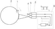
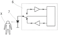
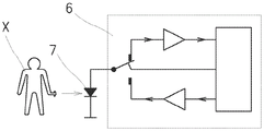
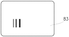
在附图中示意性地表示了本发明,其中图1a和图1b示出了本发明在光学传感器的情况下的使用,该光学传感器主要意图在环锭纺纱机器的工作站处监视环锭上钢丝圈的移动,图2a和图2b图示了本发明在LED信令部件中的使用,该LED信令部件主要意图视觉地通知操作者和/或服务机器人关于工作站的状态,图3a示出了半透明编码遮蔽部件的示例性实施例,图3b是本发明与纱线传感器和编码遮蔽部件一起使用的示意性3D表示,以及图3c是图3b的实施例的平面图。The invention is represented schematically in the accompanying drawings, wherein Figures 1a and 1b illustrate the use of the invention in the context of an optical sensor, which is mainly intended to monitor the on-ring at the workstation of a ring spinning machine Movement of the traveller, Figures 2a and 2b illustrate the use of the present invention in an LED signalling component primarily intended to visually inform the operator and/or the service robot about the status of the workstation, Figure 3a shows Fig. 3b is a schematic 3D representation of the invention in use with a yarn sensor and a coded mask, and Fig. 3c is a plan view of the embodiment of Fig. 3b.
具体实施方式Detailed ways
将参考纺织机器上特别是环锭纺纱机器上的示例性实施例来描述本发明,即参考光学传感器的辅助使用,该光学传感器主要意图在环锭纺纱机器的工作站处监视环锭上钢丝圈的移动,以及LED信令部件的辅助使用,该LED信令部件主要意图视觉地通知操作者和/或服务机器人关于工作站的状态。The invention will be described with reference to an exemplary embodiment on a textile machine, in particular a ring spinning machine, i.e. with reference to the auxiliary use of an optical sensor, which is mainly intended to monitor the wires on the ring at the work station of the ring spinning machine The movement of the circle, and the auxiliary use of LED signalling means, which are mainly intended to visually inform the operator and/or the service robot about the status of the workstation.
环锭纺纱机器包括彼此相邻布置的一行工作站。每个工作站包括可旋转的驱动轴,所述驱动轴上放置有管。在管上,在纺纱期间以已知的方式形成纱线卷装,从而形成管纱,即具有卷装的管。所述轴被可旋转地驱动。气囊限制器、导纱器和粗纱牵伸设备被布置在线筒上方。纱线从粗纱通过牵伸和加捻形成,并且随后在管上卷绕成线桶。公共环锭工作台被分派给一行工作站。环2借助于保持器附接到环锭工作台,钢丝圈1可移动地安装在该环2的冠部上。每个工作站的可旋转轴穿过环2的中心。在纺纱期间,钢丝圈1围绕环2的冠部围绕管纱运行,因为它是通过由于管纱的旋转而卷绕在管上的纱线驱动的。The ring spinning machine comprises a row of workstations arranged next to each other. Each workstation includes a rotatable drive shaft on which the tube is placed. On the tube, a yarn package is formed during spinning in a known manner to form a cop, ie a tube with the package. The shaft is rotatably driven. Airbag limiters, yarn guides and roving drafting devices are arranged above the bobbins. The yarn is formed from the roving by drafting and twisting, and is then wound into a bobbin on a tube. A common ring table is assigned to a row of workstations. A
环2与钢丝圈1移动的光学传感器3相关联,该光学传感器3包括辐射源4和反射光学接收器5。光学传感器3检测由钢丝圈1穿过由辐射源4辐射的相应环2区带的通过所引起的光场中的改变,鉴于本发明,这是光学传感器3的主要功能。为了实现该主要功能,钢丝圈1的传感器3连接到控制和评估设备6,该控制和评估设备6控制辐射源4并且处理来自反射光学接收器5的信号。根据本发明,钢丝圈1的传感器3的控制和评估设备6被提供有用于将传感器3切换到辅助操作模式的部件,在所述辅助操作模式下,辐射源4生成模拟钢丝圈1在环2上的移动的时间调制辐射,即,所述时间调制辐射在由传感器3拾取并由控制和评估设备6评估之后,其自身表现为钢丝圈1在环2上的移动,而钢丝圈1实际上没有在环上移动。更进一步地,为了提高光学传感器3的主要和辅助操作模式的差异化,期望的是,钢丝圈1在环2上的该模拟移动的参数不同于纱线生产期间钢丝圈1的实际或预期参数,例如钢丝圈1穿过被监视的环2区带的模拟通过的频率不同于纱线生产期间钢丝圈1通过被监视的环2区带的实际或预期的频率。理想地,该参数差异化以这样的方式执行,即控制设备6控制辐射源4,使得由辐射源4生成的辐射具有期望的参数,这意味着控制和评估设备6被提供有用于在钢丝圈1移动的传感器3的主要和辅助操作模式这两者下控制辐射源4的部件。在该情况下,系统(或更具体地,控制和评估设备6)知道或发现相关传感器3被切换到辅助操作模式,并且控制和评估设备6激活用于评估该辅助模式的部件。由此可见,控制和评估设备6被提供有用于控制和评估传感器3的辅助操作模式的部件。出于操作原因,如果这是在工作站没有正在纺纱,即当没有正在生产纱线的时候,或者当来自钢丝圈移动的传感器的信号没有被评估为或者不被认为是钢丝圈1在环2上的实际移动的时候进行的,则是有利的。如果在所描述的钢丝圈1移动传感器3的辅助操作模式下传感器3被遮蔽,例如,如果通过有意地将非反射元件插入从辐射源4引导到反射光学接收器5的辐射路径中,则钢丝圈1在环2上的模拟移动的检测被中断,这被控制和评估设备6检测为模拟的钢丝圈1移动的中断。该状态的检测,即钢丝圈1的模拟移动的中断的检测,可以被利用在机器操作期间可能发生的各种情况中。The
在环锭纺纱机器的工作站处使用钢丝圈1移动传感器3的辅助操作状态的一种可能性是要确认特定工作站处的操作者干预,在此期间,钢丝圈1移动传感器3及其辐射源4被有意地切换到上述辅助操作状态,并且一旦操作者在给定工作站处完成服务操作,操作者就例如通过在钢丝圈1移动传感器3和环2之间短暂插入遮蔽物20,来简单地遮蔽在该工作站处的钢丝圈1移动传感器3,这由根据本发明来配置的控制和评估设备6检测,并且被识别为特定工作站处的干预已经终止并且有可能开始给定工作站的操作的接下来步骤的信息等。因此,操作者没有必要例如激活确认按钮等。One possibility to use the auxiliary operating state of the
在一些应用中,当不需要传感器的主要功能时,例如在纱线断裂时,优选不要在整个时间期间将传感器3切换到辅助模式,但是优选在适当的情况下改变主要和辅助模式,使得传感器3的辅助功能被完全保持,而主要功能被完全或仅部分保持。在该情况下,控制和评估设备6能够识别传感器3的完全活动的辅助功能(例如,在干预终止之后检测操作者对传感器3的有意遮蔽)以及传感器3的活动的主要功能(例如,根据从环反射的光,它能够识别在特定工作站处的旋入,以及随后在恢复的稳定纺纱期间钢丝圈1在环2上的规则移动)。在活动的主要功能的该检测之后,通常不再有必要将传感器3切换到辅助模式,并且传感器保持在其操作的主要模式下。In some applications, when the main function of the sensor is not required, such as when a yarn breaks, it is preferable not to switch the
在环锭纺纱机器的工作站处使用钢丝圈移动传感器3的辅助操作状态的另一示例是将各个工作站寻址到机器控制系统。具有彼此相邻地布置的1000个或更多个工作站的环锭纺纱机器并非是不常见的。为了这样的机器的适当操作,每个工作站必须被适当地寻址到控制系统。迄今为止,这是手工进行的,并且是漫长而费力的处理。通过利用本发明,该处理被大大加速并且简化,使得在机器上,例如,当它第一次启动时,在各个工作站处的钢丝圈移动传感器3被切换到上述的辅助操作模式,即,其中在每个工作站处的辐射源4通过使光通量变化来模拟钢丝圈1的通过的模式,并且通过相应的控制和评估设备6在每个工作站处检测钢丝圈1的这些模拟通过。然后,当操作者例如通过纸或塑料或其它合适的卡片或另一合适的遮蔽部件20按照相继的各个工作站的顺序相继遮蔽在整行工作站的各个工作站处钢丝圈移动的传感器3时,这就足够了,并且控制和评估系统6识别(标识)各个工作站,并且因此,机器系统将每个特定的传感器3分派给各个工作站,而不需要手动输入工作站的数量。在这样的寻址之后,在工作站处监视钢丝圈1的系统切换回到主要操作模式,在该主要操作模式中,在相应的工作站处监视钢丝圈1在环2上的实际移动。Another example of an auxiliary operating state using the
使用在辅助模式下操作的光学传感器3形式的物理量传感器的另一示例将是例如在转子或喷气纺纱机器的工作站处使用纱线存在光学传感器,其中在转子或喷气纺纱机器的工作站处,传感器3被切换到辅助操作状态,由此操作者或服务机器人在执行服务操作之后遮蔽传感器3,这被控制系统检测为在特定工作站处的操作者干预的确认。具有其辐射源4和辐射接收器5的光学传感器3在这里充当物理量传感器。Another example of using a physical quantity sensor in the form of an
本发明也可以充分地应用于能够切换到辅助操作模式的工作站或工作站组或机器的其它元件。允许此的典型元件是信令部件LED 7,在其主要操作模式(功能模式)下,所述信令部件LED 7发出光、视觉上可感知的信号,作为关于工作站、工作站组或机器等的状态的信息。根据本发明,主要意图发出辐射的LED 7被有针对性地切换到辅助操作模式,在所述辅助操作模式下,它能够检测环境辐射。通常,检测与相应的LED 7能够发射的辐射的波长可比较的辐射波长。按照需要,但是尤其是当有必要传输在工作站、工作站组、机器等处的信息和/或操作者活动数据的时候,将LED 7切换到辅助模式。LED 7连接到控制和评估设备6,所述控制和评估设备6通过控制相应LED 7的输入和输出来控制相应LED 7在主要操作模式(即辐射发射)和辅助操作模式(即入射(环境)辐射检测)之间的有意切换。因此,在正常的主要模式下,LED 7发出辐射并且向操作者或服务机器人提供关于状态的信号,例如需要在工作站处的干预,而在辅助模式下,LED 7接收环境辐射或其改变,并且控制和评估设备6能够识别由辅助操作模式下的该LED 7所接收的辐射量。例如,这可以用于以不同的方式向控制和评估设备6传输信号,例如,包括在特定工作站的操作终止时由操作者对相应的LED 7进行简单的遮蔽,或者相反,由操作者X对LED 7进行附加的照明,传输更复杂的信息,例如切换到接收环境辐射的辅助模式的相应视觉信令LED 7的所创建的(或所编码的)各种系列的照明和遮蔽,直到借助于合适频率的合适调制辐射的光信号传输更复杂的信息,所述光信号之后可以经由切换到辐射接收器的辅助模式的主要视觉信令LED 7传输到控制和评估设备6。通过在相应LED 7的辅助操作模式下的该信号编码,还可能的是精确地标识这样的代码的发射器的来源,从而增加安全性。The invention is also fully applicable to workstations or groups of workstations or other elements of a machine that can be switched to an auxiliary mode of operation. A typical element allowing this is the
在辐射接收器的辅助模式下使用视觉信令LED 7的另一示例是,例如,出于与前面段落中所描述的类似的目的,在转子或空气喷射纺纱机器的工作站处使用视觉信令LED 7。这里,视觉信令LED 7实现了光学信令部件的功能。Another example of the use of the
纺织机器一般包括多个其它感测元件,所述感测元件意图执行检测或提供视觉信息的主要功能,并且根据本发明,这些感测元件可以有针对性地切换到辅助操作模式,在所述辅助操作模式下,这些主要感测或主要信令部件用于它们最初并不意图并且当前有必要针对其在机器上使用专有的解决方案、部件或程序的辅助目的,由此检测或视觉信息的主要功能在辅助操作模式下不活动。Textile machines generally comprise a number of other sensing elements intended to perform the main function of detecting or providing visual information, and which according to the invention can be switched in a targeted manner to an auxiliary mode of operation, in which In secondary operating mode, these primary sensing or primary signaling components are used for secondary purposes for which they were not originally intended and are currently necessary for the use of proprietary solutions, components or procedures on the machine, thereby detecting or visualizing information The main function of is not active in auxiliary operating mode.
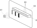
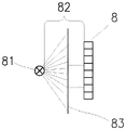
根据本发明可使用的这样的其它感测元件中的一个是纱线光学传感器,其包括至少一行8彼此相邻布置的辐射敏感元件80,例如CCD传感器或CMOS传感器等。图3a、3b和3c中示出了示例。辐射源81,例如LED,对照辐射敏感元件80的行8作为标准定位。在辐射源81和辐射敏感元件80的行8之间存在间隙82,其用于未图示的纱线的通过。辐射敏感元件80耦合到其辐射的评估设备。该类型传感器的主要操作模式是监视和评估纱线,例如评估纱线的存在或质量等。将该纱线传感器用于本发明在于,传感器切换到辅助模式,在该辅助模式下,在辐射源81和辐射敏感元件80的行8之间的间隙中不存在纱线。辐射源81直接向辐射敏感元件80的行8发出与主要操作模式下相同或更低或更高强度的辐射。一旦操作者在相应的工作站处完成工作,他或她就简单地将合适的遮蔽部件83插入辐射源81和辐射敏感元件80的行8之间的间隙中。这被评估设备检测为对辐射敏感元件80中的所有或一些的遮蔽,并且被认为是来自操作者的确认工作站处工作终止的信号。为了改进该信令的安全性,例如为了避免由意外遮蔽辐射敏感元件80的行8而造成的错误,或者为了标识特定的人或操作者,遮蔽部件83由半透明材料形成,例如在其上例如以条形码等形式形成遮蔽图案的塑料卡片,由此,在插入遮蔽部件83之后,多个辐射敏感元件80在行8中的某些相对位置处被遮蔽,并且评估设备被提供有用于标识该代码、标识操作者等的部件,使得它不仅能够识别正在进行遮蔽的事实,而且能够标识该遮蔽的来源。One of such other sensing elements which can be used according to the invention is a yarn optical sensor comprising at least one
Claims (13)
Applications Claiming Priority (3)
| Application Number | Priority Date | Filing Date | Title |
|---|---|---|---|
| CZPV2018-88 | 2018-02-22 | ||
| CZ2018-88A CZ201888A3 (en) | 2018-02-22 | 2018-02-22 | Method of controlling an optical element at a workstation of a textile machine, in particular a yarn manufacturing machine and a textile machine |
| PCT/CZ2019/050007 WO2019161816A2 (en) | 2018-02-22 | 2019-02-22 | Method of controlling an optical element at a workstation of a textile machine, especially a yarn manufacturing machine, and a textile machine |
Publications (2)
| Publication Number | Publication Date |
|---|---|
| CN112236552A CN112236552A (en) | 2021-01-15 |
| CN112236552B true CN112236552B (en) | 2022-07-29 |
Family
ID=67687917
Family Applications (1)
| Application Number | Title | Priority Date | Filing Date |
|---|---|---|---|
| CN201980027524.0A Active CN112236552B (en) | 2018-02-22 | 2019-02-22 | Method and textile machine for controlling an optical element at a workstation of a textile machine, especially a yarn making machine |
Country Status (5)
| Country | Link |
|---|---|
| US (1) | US11697894B2 (en) |
| EP (1) | EP3755830A2 (en) |
| CN (1) | CN112236552B (en) |
| CZ (1) | CZ201888A3 (en) |
| WO (1) | WO2019161816A2 (en) |
Families Citing this family (1)
| Publication number | Priority date | Publication date | Assignee | Title |
|---|---|---|---|---|
| CN119270756A (en) * | 2024-09-29 | 2025-01-07 | 浙江恒逸石化有限公司 | Ingot passing control method, device, electronic equipment and storage medium |
Family Cites Families (19)
| Publication number | Priority date | Publication date | Assignee | Title |
|---|---|---|---|---|
| US3648027A (en) * | 1969-11-18 | 1972-03-07 | Burlington Industries Inc | Data monitoring system |
| FR2463211A2 (en) * | 1979-08-10 | 1981-02-20 | Alsacienne Constr Meca | YARNING AND CLEANING SYSTEM FOR SPINNING MACHINE |
| US4300342A (en) * | 1979-12-05 | 1981-11-17 | El-Trol, Inc. | Roving frame stop apparatus |
| IT1248072B (en) * | 1991-06-17 | 1995-01-05 | Tiziano Barea | METHOD FOR THE STATE OF A WIRE SUPPLIED TO A TEXTILE MACHINE THROUGH THE DETECTION OF ITS MOVEMENT IN FRONT OF AN OPTICAL SENSOR AND DEVICE SO OBTAINED. |
| SK278624B6 (en) | 1992-07-07 | 1997-11-05 | Miloslav Rencin | Device for producing multicomponent yarn |
| CZ299647B6 (en) | 2000-11-02 | 2008-10-01 | Rieter Cz A. S. | Device for contactless measurement of a linear textile formation, such as a yarn, thread, textile fiber, sliver and the like |
| CZ290846B6 (en) | 2001-01-10 | 2002-10-16 | Rieter Cz A. S. | Device for monitoring a moving linear textile formation, particularly yarn |
| CZ292980B6 (en) | 2002-04-10 | 2004-01-14 | Rieter Cz A. S. | Apparatus for producing component yarn and device for monitoring at least one parameter of the spun component yarn |
| JP2005535794A (en) * | 2002-08-13 | 2005-11-24 | マシーネンファブリク リーター アクチェンゲゼルシャフト | Sensor device for ring spinning machine |
| CZ2004368A3 (en) | 2004-03-15 | 2005-11-16 | Rieter Cz A. S. | Method and device for addressing a group of sensors and/or measuring apparatus on a textile, particularly ring frame |
| CN2895466Y (en) * | 2006-05-23 | 2007-05-02 | 浙江省农业科学院 | Photoelectric sensing apparatus for fiber silk yarn self-stop when broken |
| IT1393094B1 (en) * | 2009-02-19 | 2012-04-11 | Btsr Int Spa | PROGRAMMABLE SENSOR TO CHECK THE POWER OF THE WIRE TO A TEXTILE MACHINE AND METHOD FOR ITS PROGRAMMING |
| JP2011016630A (en) | 2009-07-09 | 2011-01-27 | Murata Machinery Ltd | Textile machine |
| CN202450215U (en) * | 2012-01-13 | 2012-09-26 | 顾金华 | Yarn broken end detection mechanism for photoelectric opposite-type spinning machine |
| CN103572440A (en) * | 2012-07-19 | 2014-02-12 | 乌斯特技术股份公司 | Reflecting photoelectric structure and method for yarn detection |
| CN202925215U (en) * | 2012-11-30 | 2013-05-08 | 宁波瑞能电子科技有限公司 | Monitoring system for yarn fracture detection system |
| JP6241087B2 (en) | 2013-06-14 | 2017-12-06 | 村田機械株式会社 | Yarn state detection method and yarn state detection device |
| CN206033962U (en) * | 2016-08-24 | 2017-03-22 | 宁夏如意科技时尚产业有限公司 | A problem spindle positioning system for spinning frame |
| CN106835398B (en) * | 2016-12-31 | 2018-09-18 | 山西海利普电子科技有限公司 | The control method of the rove active rotation unwinding feeding of ring throstle |
-
2018
- 2018-02-22 CZ CZ2018-88A patent/CZ201888A3/en unknown
-
2019
- 2019-02-22 CN CN201980027524.0A patent/CN112236552B/en active Active
- 2019-02-22 WO PCT/CZ2019/050007 patent/WO2019161816A2/en not_active Ceased
- 2019-02-22 US US16/971,816 patent/US11697894B2/en active Active
- 2019-02-22 EP EP19717751.2A patent/EP3755830A2/en active Pending
Also Published As
| Publication number | Publication date |
|---|---|
| CZ201888A3 (en) | 2019-09-04 |
| US11697894B2 (en) | 2023-07-11 |
| EP3755830A2 (en) | 2020-12-30 |
| WO2019161816A3 (en) | 2020-10-08 |
| CN112236552A (en) | 2021-01-15 |
| US20200385894A1 (en) | 2020-12-10 |
| WO2019161816A2 (en) | 2019-08-29 |
Similar Documents
| Publication | Publication Date | Title |
|---|---|---|
| EP0598630B1 (en) | Light curtain system with individual beam indicators and method of operation | |
| JP3854512B2 (en) | Display monitor for multi-optical photoelectric safety device | |
| US11235945B2 (en) | Device and method for determining the diameter of a yarn balloon formed by a continuous yarn at a workstation of a yarn balloon forming textile machine | |
| US7081713B2 (en) | Light grid for detecting objects in a monitoring region | |
| CN112236552B (en) | Method and textile machine for controlling an optical element at a workstation of a textile machine, especially a yarn making machine | |
| CN105297208B (en) | For assisting the equipment for connecing yarn in ring-like spinning machine | |
| CN1029496C (en) | Communication system | |
| EP2975434B2 (en) | Multi-optical axis photoelectric sensor system | |
| JP3173482U (en) | A device for monitoring the thread wound around the bobbin | |
| US5323625A (en) | Electronic feeder apparatus for automatically controlling the tension of the yarn in a knitting machine and textile machines in general | |
| CN106835478B (en) | Flat-knitting-machine color-changing method and device | |
| US11286594B2 (en) | Knitting machine with electronic auxiliary component | |
| CN210420314U (en) | Single spindle monitoring device and single spindle spinning frame monitoring device | |
| US8127699B2 (en) | Monitoring apparatus | |
| CN110015597B (en) | Method for operating a spinning or winding machine | |
| CN113165827A (en) | Method for monitoring and operating a textile machine and operating device for a textile machine | |
| EP2762619A1 (en) | Weft monitoring method and weft monitoring device for fluid jet loom | |
| CN112789563B (en) | Method and device for operating a plurality of filament production positions | |
| TWI760670B (en) | Method and system for monitoring the production of a knitting machine | |
| JPH0345765A (en) | Device for detecting breakage of yarn in warp-knitting machine | |
| EP3528014B1 (en) | Light curtain and method of operating a light curtain | |
| JP4573464B2 (en) | Multi-optical axis photoelectric sensor, display control method and display device thereof, and multi-optical axis photoelectric sensor system | |
| JPH0734939Y2 (en) | Mobile automatic machine abnormality notification device | |
| JPH037590B2 (en) | ||
| KR830000087B1 (en) | Operation state information display device of ring spinning machine |
Legal Events
| Date | Code | Title | Description |
|---|---|---|---|
| PB01 | Publication | ||
| PB01 | Publication | ||
| SE01 | Entry into force of request for substantive examination | ||
| SE01 | Entry into force of request for substantive examination | ||
| GR01 | Patent grant | ||
| GR01 | Patent grant |