CN1121959C - Bicycle display unit with rear light - Google Patents
Bicycle display unit with rear light Download PDFInfo
- Publication number
- CN1121959C CN1121959C CN00104912A CN00104912A CN1121959C CN 1121959 C CN1121959 C CN 1121959C CN 00104912 A CN00104912 A CN 00104912A CN 00104912 A CN00104912 A CN 00104912A CN 1121959 C CN1121959 C CN 1121959C
- Authority
- CN
- China
- Prior art keywords
- bicycle
- display unit
- rear light
- control unit
- display
- Prior art date
- Legal status (The legal status is an assumption and is not a legal conclusion. Google has not performed a legal analysis and makes no representation as to the accuracy of the status listed.)
- Expired - Fee Related
Links
Images


Classifications
-
- B—PERFORMING OPERATIONS; TRANSPORTING
- B62—LAND VEHICLES FOR TRAVELLING OTHERWISE THAN ON RAILS
- B62J—CYCLE SADDLES OR SEATS; AUXILIARY DEVICES OR ACCESSORIES SPECIALLY ADAPTED TO CYCLES AND NOT OTHERWISE PROVIDED FOR, e.g. ARTICLE CARRIERS OR CYCLE PROTECTORS
- B62J50/00—Arrangements specially adapted for use on cycles not provided for in main groups B62J1/00 - B62J45/00
- B62J50/20—Information-providing devices
- B62J50/21—Information-providing devices intended to provide information to rider or passenger
- B62J50/22—Information-providing devices intended to provide information to rider or passenger electronic, e.g. displays
-
- B—PERFORMING OPERATIONS; TRANSPORTING
- B62—LAND VEHICLES FOR TRAVELLING OTHERWISE THAN ON RAILS
- B62J—CYCLE SADDLES OR SEATS; AUXILIARY DEVICES OR ACCESSORIES SPECIALLY ADAPTED TO CYCLES AND NOT OTHERWISE PROVIDED FOR, e.g. ARTICLE CARRIERS OR CYCLE PROTECTORS
- B62J43/00—Arrangements of batteries
- B62J43/30—Arrangements of batteries for providing power to equipment other than for propulsion
-
- B—PERFORMING OPERATIONS; TRANSPORTING
- B62—LAND VEHICLES FOR TRAVELLING OTHERWISE THAN ON RAILS
- B62M—RIDER PROPULSION OF WHEELED VEHICLES OR SLEDGES; POWERED PROPULSION OF SLEDGES OR SINGLE-TRACK CYCLES; TRANSMISSIONS SPECIALLY ADAPTED FOR SUCH VEHICLES
- B62M25/00—Actuators for gearing speed-change mechanisms specially adapted for cycles
- B62M2025/003—Actuators for gearing speed-change mechanisms specially adapted for cycles with gear indicating means, e.g. a display
Landscapes
- Engineering & Computer Science (AREA)
- Mechanical Engineering (AREA)
- Indicating Measured Values (AREA)
- Lighting Device Outwards From Vehicle And Optical Signal (AREA)
- Illuminated Signs And Luminous Advertising (AREA)
- Arrangements Of Lighting Devices For Vehicle Interiors, Mounting And Supporting Thereof, Circuits Therefore (AREA)
Abstract
A bicycle display unit is provided for displaying information to the rider. The bicycle display unit is preferably part of a bicycle computer that is battery operated. The bicycle display unit has a display panel with a front display surface and a backlight arranged to illuminate the front display surface for viewing the information displayed thereon. The bicycle display unit also has a backlight switch command operatively coupled between the backlight and the battery to selectively turn the backlight 'on' and 'off', and a control unit that extends the life of the battery by controlling the illumination of the backlight. The backlight switch command turns 'on' the backlight upon receiving a predetermined operational command. The predetermined operational command can be a pre-selected time period, a shifting operation, a mode change, etc. Also the control unit is operatively coupled to the backlight switch command to automatically turn 'off' the backlight upon lapse of a predetermined time period after switching the backlight to be turned 'on'. The backlight is preferably turned 'on' for predetermined time period of less than 30 seconds. Preferably, the control unit prevents the backlight from being turned 'on' that during selected hours, such as daylight hours, even if a predetermined operational command is received. A measuring device is preferably connected to the display unit to output the information on the display panel.
Description
The present invention relates to have the bicycle display unit of battery-operated rear light.More specifically say, the present invention relates to have the bicycle display unit of at least one rear light, display panel before this rear light illuminates with power save mode.
Just becoming a kind of entertainment form and vehicle of popularizing day by day by bike.And, by bike amateur and professional person have been become a kind of very general emulation drive.No matter bicycle is to be used for amusement, the vehicle are still competed, and how soon what understand for the rider in modern times that they ride is very favourable.Like this, the speed indicator rigging of bicycle has become a kind of additional device of popularizing day by day.In fact, some bicycle just has the device that is used to represent bicycle speed when selling.
The old model of these speed indicator riggings is mechanically operated.These early stage speed indicator riggings show the current speed of bicycle and/or the mileage of bicycle walking usually.Also there are various defectives mechanically in these early stage speed indicator riggings.A reason of problem is the means that the speed indicator rigging detecting wheel rotates.Many speed meters have a counting assembly that protrudes from spoke, and each wheel is gear of feeding or counter wheel.But these install also unreliable and may damage.So just produced the sensor of induction type, this sensor does not need actual contact between spoke annex and sensor.
And along with the technological advance of computing machine and Eltec aspect, mechanical device is replaced by electronics package, and the latter can provide than bicycle speed and/or bicycle walking mileage more information.These electronics packages are called the bicycle computer, and it comprises the various sensors that are connected in display board or element.The bicycle computer can often be measured, and calculate and show various parameters, bicycle speed for example, the distance of walking, the time that passes, the time of operation, the current time, rider's step is applied to the moment of torsion of bottom fulcrum and the gear of speed-changing mechanism.These bicycle computers also can provide the information about the rider sometimes, for example rider's pulse, blood pressure and other parameters.
The display part of bicycle computer or plate usually adopt a Liquid Crystal Display (LCD) (LCD) because by day under the riding condition rider still can read easily.But, at night or dark period this telltale, if not impossible words, then be difficult to read.Therefore, the display part that has of some bicycle computer or display panel comprise a lamp of display panel or display part of throwing light in dark period.Usually, the rider by next key to turn on the light.In case the rider discharges this key, lamp promptly extinguishes.A problem of this scheme is that the rider must finish an independent action with the information on the observation display.And the efficient of lamp is low, makes battery life shorten dramatically.And, may touch these buttons by accident by day and consumes battery without rhyme or reason.Therefore, be desirable to provide a kind of bicycle computer, it does not need the rider to push button, and only needs to watch telltale by bike or under the light conditions at night.And, being desirable to provide the lamp that a kind of telltale is used, it can avoid the accidental light that uses as far as possible, to save the energy of battery.
In view of this, need a kind of bicycle display unit that has the rear light of battery-operated, it can overcome the problems referred to above of the prior art.The present invention is exactly that those skilled in the art can obviously find out this point from specification sheets in order to solve this needs and other needs.
An object of the present invention is to provide a kind of bicycle display unit that has the rear light of battery-operated, this rear light can extend the life of a cell.
Another object of the present invention provides a kind of bicycle display unit with rear light, and this rear light can not worked in the selected period.
By providing a kind of bicycle display unit to achieve the above object basically, this bicycle display unit comprises a display part, a rear light, a rear light switch order and a control unit.This rear light is arranged to illuminate display part so that observe display part.This rear light switch order is operably connected to rear light selectively to connect and to close this rear light.The predetermined operating order of this rear light switch order response is connected this rear light.This control unit is operably connected to this rear light switch order so that in case after connecting this rear light a scheduled time slot pass and promptly automatically close this rear light.This predetermined periods is preferably less than 30 seconds.This control unit prevents that this rear light from connecting in a selected time gap, even receive the operating order that this is predetermined.
This display part is Liquid Crystal Display (LCD) (LCD) etc. preferably.This display part has the display surface of a demonstration information, and described rear light is arranged to the described preceding display surface of indirect lighting, so that observe the described information that shows thereon.
Bicycle display unit of the present invention comprises also that preferably one or more is connected in the measurement mechanism of display part, with output information on display part.This measurement mechanism can comprise that one produces the timer device of predetermined operational instructions, and this operating order is sent to the rear light switch order to connect rear light one predetermined periods.An one of them measurement mechanism preferably speed is determined element.
Bicycle display unit of the present invention preferably also comprises a battery unit, is connected in described rear light conductively with to its supply of electrical energy.
In selected embodiment of the present invention, this display part and rear light are installed in one to have in the housing of fabricated section.
The control unit of bicycle display unit of the present invention preferably also comprises a micro computer.This control unit is operably connected to a bicycle speed-varying unit assembly, and the latter produces a predetermined operating order during variable speed operation, connects with the indication rear light.The bicycle shift assembly comprises at least one speed change part, produces described predetermined operational instructions by operating described at least one speed change part.
Bicycle display unit of the present invention preferably is integral with a bicycle shift assembly that is operably connected to control unit, to show speed change information on display part.The bicycle shift assembly comprises at least one speed change part.This display part, rear light and bicycle shift assembly can be installed on the bicycle.For example, the speed change part, rear light, display part and bicycle shift assembly are installed in the housing together, and the latter is installed on the handle bar of bicycle.In one embodiment, control unit is in rear light and display part are installed in an independent unit, and the latter is installed on the handle bar of bicycle.As selection, rear light and display part can be installed in one first housing together, and control unit can be installed in one second housing.
In selected embodiment, the bicycle shift assembly can be the part of an automatic transmission system, and the latter has dynamic model formula and at least one automatic mode on the other hand.At manual mode, the rider manually finishes gear shift.At automatic mode, gear is gear shift automatically.Under any circumstance, each gear shift produces a predetermined operational instructions of delivering to control unit.In a kind of like this bicycle shift assembly, control unit is operably connected to the bicycle shift assembly, and such pattern map function produces this predetermined operating order.
The best scalable of control unit is to change the length of selected time gap.The selected time gap of control unit also can preestablish in factory.The preferable range of scheduled time slot is between about one second to about six seconds.
By show that to the rider method of information also can reach purpose of the present invention under low light state, the energy of battery has been saved in the operation of rear light like this.The step that method of the present invention consists essentially of is a demonstration information on a telltale, this telltale is provided with battery-operated rear light, with information shown on the illuminated displays, and rear light one is connected and closed to the predetermined operating order of response selectively less than 30 seconds scheduled time slot.Can not operate at predetermined lights down periods rear light.
Those skilled in the art can obviously find out these and other purposes of the present invention from the following detailed description, feature, and aspect and advantage, following description discloses the preferred embodiments of the present invention in conjunction with the accompanying drawings.
Now, with reference to the accompanying drawing that constitutes an original open part:
Fig. 1 is the lateral plan of a bicycle, is equipped with one on it according to bicycle display unit of the present invention;
Fig. 2 is the scheme drawing according to bicycle display unit of the present invention;
Fig. 3 is a diagram of circuit, shows the process of an example connection according to the rear light of display unit of the present invention;
Fig. 4 is the front elevation of bicycle display unit shown in Fig. 1-3, is installed near the handle bar of handle of bicycle;
Fig. 5 is the enlarged view of a part, shows the display board according to display unit of the present invention;
Fig. 6 is a back view, shows according to display unit shown in Figure 4 of the present invention;
Fig. 7 is a lateral plan, shows according to the bicycle display unit shown in Fig. 4 of the present invention-6;
Fig. 8 is a decomposition diagram, shows according to the bicycle display unit shown in Fig. 4 of the present invention-7;
Fig. 9 is a sectional elevation, shows along the display unit shown in 9-9 line being seen Fig. 4-7 among Fig. 5;
Figure 10 is another cutaway view, shows along the display unit shown in 10-10 line being seen Fig. 4-8 among Fig. 5;
Figure 11 is the transparent view according to the display unit of first embodiment of the invention, is connected near the brake equipment;
Figure 12 is the transparent view according to the display unit of second embodiment of the invention;
Figure 13 is the transparent view according to the display unit of third embodiment of the invention;
Figure 14 is the transparent view according to the display unit of fourth embodiment of the invention.
At first with reference to Fig. 1, show a bicycle 10, have bicycle display unit 12 according to an embodiment of the invention, the latter is installed on this bicycle as discussed below.This bicycle display unit is a bicycle computer preferably, can measure, calculate the various parameters relevant with demonstration and bicycle 10, for example speed of a motor vehicle, travel distance, the time of stretch journey, time of run, now, rider's rhythm is applied to moment of torsion and gear on the fulcrum of bottom.If desired, bicycle computer or telltale 12 also can be the rider for example rider's pulse are provided, blood pressure and other parameters.As described below, bicycle display unit 12 is arranged in the low luminous environment especially to the rider shows information, saves the energy simultaneously.
Bicycle 10 is a standard bicycle that has a vehicle frame 14 preferably, has a front vehicle wheel 16, one rear wheels 18, one vehicle seats 20, and one handle bar 22 and is in order to drive the drive-system parts 24 of bicycle 10.Bicycle 10 and various parts thereof are known in this field.So,, will no longer go through or illustrate bicycle 10 and various parts thereof here except for explaining that the present invention is necessary.And in the embodiment that at first illustrates, display unit 12 also is used for mobile drive-system parts 24, and the latter is an automatic driving device.Certainly, can find out obviously that to those skilled in the art this display unit 12 can be used in combination with manually operated drive-system parts.
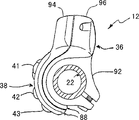
Can be clear that from Fig. 2 and 8 bicycle display unit 12 consists essentially of display panel or display part 28, one control units or parts 32 and a battery unit or parts 34 that have an a pair of rear light 30, they are installed in the housing 36 together.Bicycle display unit 12 preferably is fixedly mounted in the part place of handle bar 22 near one of them handle.In the embodiment shown, bicycle display unit 12 is parts of a speed change assembly 38, and the latter is operatively coupled on the drive-system parts 24.
Certainly, those skilled in the art can find out obviously that from present disclosure other embodiment also are possible, disclosed herein is the part of these embodiment.For example, as shown in figure 12, control unit 32 separates actually with display board 28, and display board 28 is installed in the middle part of handle bar 22 like this, and control unit 32 then is positioned near the handle.And shown in Figure 13 and 14, bicycle display unit 12 can separate with speed change assembly 38.
In the embodiment shown, speed change assembly 38 is operably connected to fast inner speed-variating hub 40 more than by a speed change cable 39, and the latter is installed in rear wheel 18 on the vehicle frame 14.Certainly, those skilled in the art can find out obviously that from this specification sheets the speed change assembly that can adopt other types and drive-system parts in conjunction with display unit 12, cause advantage of the present invention to reach.
In this field, the inside speed-variating hub of inner speed-variating hub 40 and so on is known.Like this, here, will no longer go through or illustrate inner speed-variating hub 40.The U.S. Patent No. 5,900,705 that transfers Shimano company discloses a routine inner speed-variating hub and a speed change assembly, and its technology can be with in the present invention.U.S. Patent No. 5,900,705 whole open text is incorporated herein by reference, so that understand the inside speed-variating hub that is connected in an automatic speed changing assembly.
Shown in Fig. 4 and 8, speed change assembly 38 has three variable speed bonds or switch 41,42 and 43.Switch 41-43 is button preferably, is operably connected to control unit 32 and inner speed-variating hub, in order to send signal to the gear shift action of inner speed-variating hub 40 and/or it is controlled.For example, switch 41-43 has cap portion 41a, and 42a and 43a and contact portion 41b, 42b and 43b, the latter are formed on the ribbon cable 44 that is connected in control unit 32 conductively.In case press switch 41, a signal is just delivered to the control unit 32 of handling this signal, respond the rider then and press one of them switch 42 or 43, this control unit 32 or automatically control the gear shift of inner speed-variating hub 40 or control the gear shift of inner speed-variating hub 40.Just deliver to the control unit 32 of handling this signal in case press one of them switch 42 or 43, one signals, control unit 32 is just sent the signal of a gear shift up or down to inner speed-variating hub 40 then.
Switch 41 is a mode switch preferably, and it allows rider's conversion between an automatic shift mode and a manual speed change pattern.And, automatic shift mode preferably have two with a plurality of different automatic modes, to be used for the different conditions of riding.Therefore, by pressing mode switch 41, the rider can be switched between a manual shift mode and one of them automatic shift mode.When not operating bicycle 10, switch 41-43 can use with adjusting key 51, to set and regulation control switch 32.Device with a bar pen or band point promotes regulating part 51, to activate the regulating circuit of control unit 32.For example, if keep mode switch 41 to press, varying speed switch 42 and 43 can be used to set and/or regulating control unit 32.
When the rider selected automatic shift mode by pressing mode switch 41, control unit 32 automatically made inner speed-variating hub 40 gear shift.Say that more specifically the speed of control unit 32 definite bicycles 10 and current gear are to determine when upwards gear shift or gear shift downwards.Therefore, control unit 32 has a program that stores within it, uses so that 40 gear shift of inner speed-variating hub.Display board 28 preferably shows the current gear and the speed of bicycle 10.Each inner speed-variating hub 40 is transformed into top grade from low grade, and perhaps top grade is transformed into low grade, produces and be sent to control unit 32 once predetermined operating order or signal.Control unit 32 will determine whether to light rear light 30 then.
When the rider selects manual shift mode, make inner speed-variating hub 40 gear shift by operation control or varying speed switch 42 and 43.Switch 42 button preferably for example, it makes inner speed-variating hub 40 transform to a high speed gear from a low gear.Switch 43 is the button of a downward speed change preferably, and it instructs inner speed-variating hub 40 gear shift to next low gear.Display board 28 shows that preferably which in three patterns the rider using at present.And display board 28 preferably shows the current speed of the current gear and the bicycle 10 of inner speed-variating hub 40.
Main numerical value display part 46 preferably is designed to have at least and selectively shows such as kilometer/hour (km/h), or miles per hour (mile/h), or the information of gear and so on.In other words, main numerical value display part 46 preferably provides the information about current bicycle speed and current gear.Certainly, can be as required and/or require to provide selectively the information of other types in main numerical value display part 46.Main numerical value display part 46 is operably connected to control unit 32.Best, control unit 32 showed current bicycle speed and show checker between the current gear in a period of time in a period of time.
Less important numerical value display part 47 preferably provides the current time, current temperature, the information of the ride time and the distance and so on of riding.Certainly, can be as required and/or require to provide selectively the information of other types in less important numerical value display part 47.Control unit 32 is operably connected to less important numerical value display part 47.After a schedule time passed, control unit 32 is the shown information of checker automatically preferably.Select as another kind, an additional key is operably connected to control unit 32, to change current shown information selectively.
Those skilled in the art can find out obviously that from specification sheets the various structures that are used for display board 28 all are possible, and this display board 28 is configured to show the various information from control unit 32 outputs.In the bicycle field, some examples of prior art bicycle display comprise the United States Patent(USP) Nos. 5,847,641 and 5,625,336 that transfers Shimano company.These patents are incorporated herein by reference, and can be used on the various information that various circuit on the control unit 32 and/or available display unit 12 show with demonstration.
The period of this preliminary election or light can be set in factory and/or rider the period of closing.For example, control unit 32 can comprise a program, requires the rider to import the current time, current date and current time zone, and control unit 32 can be optimized length and the timing that light is closed period like this.In other words, control unit 32 can automatically be regulated the power saving time on daytime, and rider's geographic position.Certainly, prerequisite is that the rider has correctly imported the residing geographic position of current time, date and rider.
Select as another kind, the rider can be light and closes the programming in period.For example, the rider can import light and is from 6:00a.m. to 8:00p.m. the period of closing.Certainly, open by day, just require the rider constantly to regulate display unit and close period to optimize light in order to prevent rear light 30.
Another kind of possibility is to adopt a light sensor 54 to control light to close period.Light intensity around light sensor 54 will determine when is fallen under the predetermined strength, and therefore lights rear light 30.In this case, light intensity around is enough to any time of the mark on the observation display plate 28, can enter light and close period.Certainly, those skilled in the art can find out obviously that from specification sheets the various combinations of these methods all can be used to definite light and close period.
Wish that generally the rider needn't connect rear light 30 by the independent key of the next one and just can light this rear light.Certainly, if desired and/back requirement can increase so independent key to light rear light 30.If adopt an independent key, be inoperable at this key of light down periods, in case inadvertently or by accident light rear light 30 by day.
As selection, can when pressing mode key or switch 41, light rear light 30 at every turn, this button switches between one of them automatic mode or from one of them automatic mode dynamic model formula in one's hands, and vice versa.Another kind of possibility is with the illumination of master cock 32 according to time control rear light 30.Specifically, rear light 30 can be connected predetermined periods every 5 minutes.In case predetermined periods passes, can extinguish rear light 30.The frequency that rear light 30 is connected can be regulated in factory set and/or by the rider.Certainly, can select among the embodiment at each, rear light 30 is not taken in light down periods work, the accidental rear light 30 of lighting when preventing by day.
A kind of sensing/measuring cell in order to control rear light 30 is an operation or a gear position sensor 70.Operation or gear position sensor 70 have a potentiometer that is operably connected to central processing unit 62, in order to survey the current gear of inner speed-variating hub 40.Can gear position sensor 70 be installed on the inner speed-variating hub 40 with traditional approach.Under the situation of manual transmission, gear position sensor can be installed on each speed change assembly and/or the forward and backward group of chain device on.Gear position sensor 70 produces an analog signal (operating order of being scheduled to), and this signal converts digital signal to by a signaling conversion circuit of central processing unit 62.This digital signal is sent to display board 28 then.The predetermined operational instructions of gear position sensor 70 also is used for controlling rear light 30.
Another kind of sensing/measuring cell in order to control rear light 30 is a bicycle car speed sensor 72.Car speed sensor 72 is connected on the front fork of bicycle 10.This car speed sensor 72 is exported a bicycle vehicle speed signal by the magnet 74 that detection is installed on the front-wheel 16.Like this, one of sensor 72 and magnet 74 formation control units 32 is installed or measuring cell.In other words, sensor 72 detects the rotating speed of front-wheel 16 and has a front travel switch or other elements, rotates one or more magnet 74 in order to detect with wheel 16.Whenever wheel 16 turns over a predetermined angular and a circle, sensor 72 just produces a pulse.As long as sensor 72 produces a pulse or signal, an impulse singla transmission circuit is just delivered to central processing unit 62 with this impulse singla, and the latter is presented at information on the display board 28 as required.In other words, bicycle car speed sensor 72 produces an analog signal (operating order of being scheduled to), and this analog signal converts digital signal to by the signaling conversion circuit of central processing unit 62.This digital signal is delivered to display board 28 then.The predetermined operational instructions of car speed sensor 72 also is used for controlling rear light 30.
One torque sensor 76 can be used to detect rider's the power that scrunches or act on the moment of torsion of bottom on the fulcrum.Crank arm can be provided with a step sensor that is similar to car speed sensor 72, is installed on the front fork.Speed-changing mechanism and stop mechanism also can be provided with a position transduser and a transmission circuit, in order to the various information of expression about speed change and/or braking.For example, an available strain-gauge or other force gauges detect the pressure that is applied on slipper or other friction members.Torque sensor 76 produces an analog signal (operating order of being scheduled to), converts a digital signal to by the signaling conversion circuit of central processing unit 62.This digital signal is sent to display board 28 then.
One braking sensor 78 can be used to detect when apply a braking force by retainer.Braking sensor 78 is connected on the brake rod 79.Braking sensor 78 produces an analog signal (operating order of being scheduled to), converts a digital signal to by the signaling conversion circuit of central processing unit 62.This digital signal is sent to display board 28 then.The predetermined operational instructions of braking sensor 78 also is used to control rear light 30.In other words, brake rod 79 whenever applies once braking, rear light 30 predetermined periods of just will throwing light on.
Device or timing element 80 when another sensing/measuring cell that can be included in the control unit 32 is certain.Timing element 80 preferably includes a clock, and the latter shows the current time on display board 28.Timing element 80 also can be used to measure various timing sequences and be used for controlling the information that is presented on the display board 28.For example, timing element 80 is used to the time span of control " light is closed period " and rear light 30 illuminations.One predetermined operating order also can be produced by timing element 80, to control rear light 30 based on the time.
The sensor of other types also can be installed, in order to measure rider's pulse, blood pressure etc.These parameters also can be presented on the display board 28 by control unit 32.One temperature sensor (not shown) preferably also is operably connected to control unit 32, to show current temperature on display board 28.Display unit 12 interconnects by means of traditional conductor signal cable and adaptor union with the sensor that has the corresponding signal transmission circuit.
For example, as U.S. Patent No. 5,625,336 is disclosed, shows that alternately this patent transfers Shiano company in case a scheduled time slot passes the various information in back.Specifically, U.S. Patent No. 5,625,336 disclose a kind of display equipment of bicycle, have a speed converter, wherein in case after display equipment switches to speed change pattern a schedule time pass, telltale automatically switches to operational mode from speed change pattern with display equipment.This change-speed box can be with in the present invention.The whole specification sheets of this U.S. Patent No. 5,625,336 is incorporated by reference thereto, in order to understand the adoptable various features of the present invention.Certainly, other bicycle assembly parts also can be provided with sensor and the signalization transmission route of surveying various data, are transferred to display unit in order to the signal that will detect.
Cell device or unit 34 preferably include a traditional A-battery, for example employed battery in the digital watch.Although only show a battery, those skilled in the art can obviously find out if desired and/or requirement from specification sheets, can adopt more than one battery.And those skilled in the art can find out obviously that from specification sheets this battery 34 as shown in FIG. can install in the housing 36, and perhaps this battery 34 can be installed in the independent housing and be connected in control low pressure 32 in a conventional manner conductively.Battery 34 can be a traditional battery, the A-battery of for example silver-colored oxygen cell or lithium cell or any other known type.Preferably about 1.5 volts of voltage.Those skilled in the art can find out obviously that from this specification sheets this battery can be a solar cell, or the combination of standard cell that links together and solar cell.
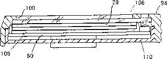
When camera lens or preceding inner casing part 106 when front casing part 94 is provided with, preceding inner casing part 106 is positioned near the reflecting surface 112 that forms in the inside of front casing part 94.This reflecting surface 112 is designed to the light that sends from rear light 30 along the front surface reflection of display board 28.In other words, rear light 30 is arranged on the printed circuit board (PCB) 60, before light is shining into like this inner casing part then by the reflecting surface 112 of front casing part 94 by preceding inner casing partial reflection.
Printed circuit board (PCB) 60 has a ribbon cable, is formed with switch on it.These switches preferably have the switch block, and the latter is arranged in the key opening of front casing part.On each switch block, be preferably formed as and the corresponding various marks of its function.For example, be printed on " pattern ", " making progress " and " downwards " on the switch block.Key opening on these switch block the past housing parts is outwards protruded, and the rider can inwardly press the switch block like this, and this just makes switch opens subsequently or closes.
Second embodiment
Referring now to Figure 12, show improved display unit 112 according to second embodiment of the invention.This embodiment and first embodiment are roughly the same basically, and just each parts or part are divided into three independently parts.In view of the similarity between this embodiment and the last embodiment, will no longer go through or illustrate this embodiment here.In other words, unless explanation, the various descriptions of present embodiment are identical or roughly the same with last embodiment of the present invention with function.
In the present embodiment, display unit 112 has a display unit housing 113, and the latter is connected in a control unit housing 115 conductively by cable 117.Control unit housing 115 is fixed tightly on the handle bar 122 and by cable 117 and is connected in display board 128 conductively.Control unit housing 115 comprises the printed circuit board (PCB) of first embodiment.But rear light 30 really is connected in the printed circuit board (PCB) of control unit housing 115 at a distance.In other words, rear light is installed on the display board housing 113.Like this, display board housing 113 is arranged near the middle part of handle bar 122.But in this embodiment, the automatic speed changing assembly is cancelled and replaces speed change assembly 138, and the latter is any known hand gear assembly.In this embodiment, speed change assembly 138 has adopted a pair of bar 139, and the latter is operatively connected the cable 141 in front chain shifter or rear derailleur.Those skilled in the art can obviously find out from this specification sheets, if desired/requirement, can replace the speed change assembly 138 of bar type with the speed-changing mechanism of the variable speed model of holding with a firm grip.In any case gear position sensor is surveyed the current gear of changeover module 138.
The 3rd embodiment
Referring now to Figure 13, show improved display unit 212 according to third embodiment of the invention.Basically, this embodiment and first embodiment are roughly the same, and just the mechanical speed change assembly 138 with second embodiment replaces the automatic speed changing assembly.In view of the similarity between this embodiment and the last embodiment, will no longer go through or illustrate this embodiment here.In other words, unless explanation, the various descriptions of present embodiment are identical or roughly the same with last embodiment of the present invention with function.
The 4th embodiment
Referring now to Figure 14, show improved display unit 312 according to fourth embodiment of the invention.This embodiment and first embodiment are roughly the same, just control button 341,342 and 343 and are installed on the housing 315 that separates with main casing 336.In view of the similarity between this embodiment and the last embodiment, will no longer go through or illustrate this embodiment here.In other words, unless explanation, the various descriptions of present embodiment are identical or roughly the same with last embodiment of the present invention with function.
Although only selected several embodiment that the present invention has been described, those skilled in the art can obviously find out from specification sheets and can make various changes or improvement and do not exceed appended claim book institute restricted portion.And, to the above description of the embodiment of the invention just for purpose of explanation, be not to be the present invention who is limited by appended claim book and equivalent thereof in order to limit.
Claims (22)
1. bicycle display unit comprises:
One display part;
One rear light is arranged to illuminate described display part so that observe described display part;
One rear light switch order is operably connected to described rear light selectively to connect and to close described rear light, and the predetermined operating order of described rear light switch order response is connected described rear light; With
One control unit, be operably connected to described rear light switch order, so that in a single day a scheduled time slot passes and promptly automatically closes described rear light after connecting described rear light, described predetermined periods was less than 30 seconds, described control unit prevents that described rear light from connecting in a selected time gap, even receive described predetermined operating order.
2. bicycle display unit as claimed in claim 1 also comprises
One is connected in the measurement mechanism of described display unit, with to display part output information.
3. bicycle display unit as claimed in claim 2, wherein
Described measurement mechanism comprises device when certain, produces described predetermined operating order and connects to indicate described rear light.
4. bicycle display unit as claimed in claim 1 also comprises
One battery unit is connected in described rear light conductively with to its supply of electrical energy.
5. bicycle display unit as claimed in claim 1, wherein
Described display part and described rear light are installed on the housing with a fabricated section.
6. bicycle display unit as claimed in claim 1, wherein
Described control unit comprises a micro computer.
7. bicycle display unit as claimed in claim 1, wherein
Described control unit is operably connected to a bicycle shift assembly, and it produces described predetermined operating order and connects to indicate described rear light during variable speed operation.
8. bicycle display unit as claimed in claim 7, wherein
Described bicycle shift assembly comprises at least one speed change part, produces described predetermined operational instructions by operating described at least one speed change part.
9. bicycle display unit as claimed in claim 7, wherein
Described bicycle shift assembly comprises the automatic mode of an autoshift and produces described predetermined operational instructions.
10. bicycle display unit as claimed in claim 1, wherein
Described control unit is operably connected to a bicycle shift assembly, and it produces described predetermined operating order changing pattern operating period.
11. bicycle display unit as claimed in claim 1, wherein
Described control unit scalable is to change the length of described selected time gap.
12. bicycle display unit as claimed in claim 1, wherein
The described selected time gap of described control unit is predefined in factory.
13. bicycle display unit as claimed in claim 1, wherein
Described predetermined periods is between one second to six seconds.
14. bicycle display unit as claimed in claim 1, wherein
Described control unit scalable is to change the length of described scheduled time slot.
15. bicycle display unit as claimed in claim 1, wherein
Described display part has the display surface of a demonstration information, and described rear light is arranged to the described preceding display surface of indirect lighting, so that observe the described information that shows thereon.
16. bicycle display unit as claimed in claim 1, wherein
Described display part is a LCD display.
17. bicycle display unit as claimed in claim 1 also comprises
One bicycle shift assembly is operably connected to described control unit, to show speed change information on described display part.
18. bicycle display unit as claimed in claim 17, wherein
Described bicycle shift assembly comprises at least one speed change part, described display part, and described rear light and described bicycle shift assembly can be installed on the bicycle.
19. bicycle display unit as claimed in claim 18, wherein
Described speed change part, described rear light, described display part and described bicycle shift assembly are installed together in a housing.
20. bicycle display unit as claimed in claim 18, wherein
Described speed change part, described rear light, described display part and described control unit are installed together in a housing.
21. bicycle display unit as claimed in claim 18, wherein
Described rear light, described display part and described control unit are installed together in one first housing, and described speed change part is installed in one second housing.
22. bicycle display unit as claimed in claim 2, wherein
Described measurement mechanism comprises that a speed determines element.
Applications Claiming Priority (3)
| Application Number | Priority Date | Filing Date | Title |
|---|---|---|---|
| US09/448421 | 1999-11-24 | ||
| US09/448,421 US6204752B1 (en) | 1999-11-24 | 1999-11-24 | Bicycle display unit with backlight |
| US09/448,421 | 1999-11-24 |
Publications (2)
| Publication Number | Publication Date |
|---|---|
| CN1304850A CN1304850A (en) | 2001-07-25 |
| CN1121959C true CN1121959C (en) | 2003-09-24 |
Family
ID=23780254
Family Applications (1)
| Application Number | Title | Priority Date | Filing Date |
|---|---|---|---|
| CN00104912A Expired - Fee Related CN1121959C (en) | 1999-11-24 | 2000-03-30 | Bicycle display unit with rear light |
Country Status (6)
| Country | Link |
|---|---|
| US (1) | US6204752B1 (en) |
| EP (1) | EP1103454B1 (en) |
| JP (1) | JP3534694B2 (en) |
| CN (1) | CN1121959C (en) |
| DE (1) | DE60025145T2 (en) |
| TW (1) | TW472011B (en) |
Families Citing this family (74)
| Publication number | Priority date | Publication date | Assignee | Title |
|---|---|---|---|---|
| JP3490239B2 (en) | 1997-01-31 | 2004-01-26 | 株式会社シマノ | Mounting device for bicycle display device |
| SE518272C2 (en) | 2000-01-07 | 2002-09-17 | Johan Ullman | Controls for watercraft and watercraft including a control knob |
| US6400564B1 (en) * | 2000-09-14 | 2002-06-04 | Shimano Inc. | Switch guide for a bicycle control panel |
| US6695090B2 (en) * | 2001-02-15 | 2004-02-24 | Motorcycle Riders Holdings Corp. | Back-lit handlebar control assembly |
| GB2373741B (en) * | 2001-03-28 | 2004-10-13 | Pro Gym Co Internat Ltd | Angle adjustable handle for exercise bike |
| US6523772B2 (en) | 2001-05-29 | 2003-02-25 | Shimano Inc. | Electric device with cord retainer for bicycle |
| US6698307B2 (en) | 2001-10-23 | 2004-03-02 | Sram Corporation | Electronic shifter for a bicycle |
| JP2003252271A (en) * | 2002-02-27 | 2003-09-10 | Shimano Inc | Display device for bicycle |
| US6664744B2 (en) * | 2002-04-03 | 2003-12-16 | Mitsubishi Electric Research Laboratories, Inc. | Automatic backlight for handheld devices |
| JP3740097B2 (en) * | 2002-07-10 | 2006-01-25 | 株式会社シマノ | Bicycle display system |
| US6781510B2 (en) * | 2002-07-24 | 2004-08-24 | Shimano, Inc. | Bicycle computer control arrangement and method |
| EP1384659B1 (en) * | 2002-07-24 | 2009-12-23 | Shimano Inc. | Bicycle computer control arrangement and method |
| JP3727292B2 (en) * | 2002-08-20 | 2005-12-14 | 株式会社シマノ | Bicycle electrical equipment drive device |
| JP2004110628A (en) * | 2002-09-20 | 2004-04-08 | Shimano Inc | Bicycle user's information management device and cycle computer |
| DE60226445D1 (en) * | 2002-10-18 | 2008-06-19 | Shimano Kk | Bicycle lighting system |
| JP2004249885A (en) * | 2003-02-21 | 2004-09-09 | Cateye Co Ltd | Handlebar stem and speed indicating device |
| US7616097B1 (en) * | 2004-07-12 | 2009-11-10 | Apple Inc. | Handheld devices as visual indicators |
| US6974222B2 (en) * | 2003-03-31 | 2005-12-13 | Honda Motor Company, Ltd. | Light distribution plenum for an illuminated control assembly and method |
| PT1582446E (en) * | 2004-03-30 | 2010-05-31 | Honda Motor Co Ltd | Vehicle provided with switch device |
| US7779724B2 (en) * | 2004-04-19 | 2010-08-24 | Shimano Inc. | Electrical bicycle shift control device |
| US7307516B2 (en) * | 2004-08-22 | 2007-12-11 | Wiegner Thomas F | Instrument viewing display system for motorcycles |
| US20060146652A1 (en) * | 2005-01-03 | 2006-07-06 | Sdi Technologies, Inc. | Sunset timer |
| US7641020B2 (en) * | 2005-04-18 | 2010-01-05 | Jungheinrich Aktiengessellschaft | Hand rail for a walkie/rider truck |
| US7534206B1 (en) | 2005-09-19 | 2009-05-19 | Garmin Ltd. | Navigation-assisted fitness and dieting device |
| JP4246741B2 (en) * | 2006-01-20 | 2009-04-02 | 株式会社キャットアイ | Display device |
| US7363873B2 (en) * | 2006-02-21 | 2008-04-29 | Shimano Inc. | Bicycle shift control device with light structure |
| US7649447B2 (en) * | 2006-03-02 | 2010-01-19 | Yen-Ho Lu | Wireless bike brake light |
| CN101195398B (en) * | 2006-12-08 | 2010-12-22 | 光阳工业股份有限公司 | Motorcycle handle connecting seat |
| ITMI20070140A1 (en) * | 2007-01-30 | 2008-07-31 | Campagnolo Srl | MAN-BICYCLE INTERACTION DEVICE |
| ITMI20070737A1 (en) * | 2007-04-12 | 2008-10-13 | Campagnolo Srl | EQUIPMENT AND ELECTRONIC SYSTEM FOR BICYCLE AND RELATIVE METHODS |
| JP4993290B2 (en) * | 2007-06-08 | 2012-08-08 | 株式会社キャットアイ | Display device |
| US7997775B2 (en) * | 2007-09-24 | 2011-08-16 | Nite Glow Industries, Inc. | High visibility safety lighting system integrated within a vehicle's frame |
| US20090088934A1 (en) * | 2007-09-28 | 2009-04-02 | Shimano Inc. | Bicycle control system |
| US7847680B2 (en) * | 2007-12-05 | 2010-12-07 | Gm Global Technology Operations, Inc. | Motor vehicle gear selector with integrated display |
| ITMI20072407A1 (en) * | 2007-12-20 | 2009-06-21 | Campagnolo Srl | ELECTRONIC EQUIPMENT FOR BICYCLE |
| JP5046909B2 (en) * | 2007-12-21 | 2012-10-10 | 株式会社日本マイクロニクス | Contact for electrical test, electrical connection device using the contact, and method for manufacturing contact |
| US8213794B2 (en) * | 2008-02-12 | 2012-07-03 | Nec Laboratories America, Inc. | Programmable optical network architecture |
| US8212426B2 (en) * | 2008-04-21 | 2012-07-03 | Shimano Inc. | Bicycle electrical wiring unit |
| CN104055355B (en) | 2008-09-03 | 2017-09-22 | 索利产业公司 | Variable motion baby seat |
| US8643722B2 (en) * | 2008-10-08 | 2014-02-04 | Cerevellum Design, Llc | Rear-view display system for a bicycle |
| WO2010103397A1 (en) * | 2009-03-13 | 2010-09-16 | Minda Industries Limited | Illuminated handle bar switch with led based construction |
| JP5571703B2 (en) * | 2009-03-13 | 2014-08-13 | ミンダ・インダストリーズ・リミテッド | Illuminated handlebar switch module |
| US9434437B2 (en) * | 2009-07-23 | 2016-09-06 | Harley-Davidson Motor Company Group, LLC | Master cylinder-mounted display for a motorcycle |
| FI20095888A0 (en) * | 2009-08-28 | 2009-08-28 | Polar Electro Oy | The cycling computer |
| US20110049206A1 (en) * | 2009-09-02 | 2011-03-03 | Su-Chang Liao | Tie-able securing device for bicycle |
| KR100966120B1 (en) * | 2009-12-28 | 2010-06-25 | 이창용 | Automatic transmission gear box of bicycle |
| JP5633154B2 (en) * | 2010-02-18 | 2014-12-03 | 豊田合成株式会社 | Semiconductor light emitting device manufacturing method, semiconductor light emitting device, lamp, electronic device, and mechanical device |
| US9664221B2 (en) * | 2011-01-14 | 2017-05-30 | Armando Camacho | Expanding devices |
| JP5808187B2 (en) * | 2011-07-29 | 2015-11-10 | 川崎重工業株式会社 | VEHICLE CONTROL DEVICE, VEHICLE HAVING THE CONTROL DEVICE, AND ITS CONTROL METHOD |
| US8781690B2 (en) * | 2011-11-28 | 2014-07-15 | Shimano Inc. | Bicycle seat position indicator |
| GB201311001D0 (en) * | 2013-06-20 | 2013-08-07 | Lucabella Holdings Llc | Lucabella |
| JP6220637B2 (en) * | 2013-11-01 | 2017-10-25 | ヤマハ発動機株式会社 | Electric assist bicycle |
| JP6220636B2 (en) * | 2013-11-01 | 2017-10-25 | ヤマハ発動機株式会社 | Electric assist bicycle |
| USD752264S1 (en) | 2013-11-26 | 2016-03-22 | Dynacraft Bsc, Inc. | Light assembly for a bicycle |
| US20150233560A1 (en) * | 2014-02-14 | 2015-08-20 | Zealio Electronics Co., Ltd. | Wireless light board |
| TWI580591B (en) | 2014-02-14 | 2017-05-01 | 智佳電子股份有限公司 | Wireless light board |
| JP6228048B2 (en) * | 2014-03-18 | 2017-11-08 | ブリヂストンサイクル株式会社 | Electric assist bicycle |
| TWI541621B (en) * | 2014-09-15 | 2016-07-11 | 神達電腦股份有限公司 | Watch and method for automatically turning on a backlight |
| EP3337721A1 (en) | 2015-08-25 | 2018-06-27 | Biketec AG | Electric bicycle |
| CN105523114A (en) * | 2015-12-28 | 2016-04-27 | 小米科技有限责任公司 | Stopwatch, riding tool and method for measuring riding parameters |
| JP6674305B2 (en) * | 2016-03-31 | 2020-04-01 | 太陽誘電株式会社 | Display operation device and electric assist vehicle |
| CN206087036U (en) * | 2016-04-28 | 2017-04-12 | 乐视控股(北京)有限公司 | Tape unit head display device's bicycle |
| JP6761314B2 (en) * | 2016-09-15 | 2020-09-23 | ヤマハ発動機株式会社 | Electric auxiliary bicycle |
| JP6825901B2 (en) * | 2016-12-22 | 2021-02-03 | 株式会社シマノ | Bicycle display device |
| JP6942018B2 (en) * | 2017-08-30 | 2021-09-29 | 太陽誘電株式会社 | Display operation device for vehicles and bicycles |
| JP6970556B2 (en) * | 2017-08-30 | 2021-11-24 | 太陽誘電株式会社 | Display devices and bicycles for bicycles or motorcycles |
| DE202017105766U1 (en) | 2017-09-22 | 2019-01-08 | Ovibell Pflanzen, Deko Und Freizeit Gmbh & Co. Kg | wall mount |
| CN108791679A (en) * | 2018-07-02 | 2018-11-13 | 南京溧水电子研究所有限公司 | Control suitable for Moped Scooter shows all-in-one machine |
| TWI697431B (en) * | 2019-05-08 | 2020-07-01 | 彥豪金屬工業股份有限公司 | Bicycle head |
| JP7525249B2 (en) * | 2019-05-16 | 2024-07-30 | 株式会社シマノ | An interface device for human-powered vehicles. |
| US10789790B1 (en) * | 2019-09-23 | 2020-09-29 | Lyft, Inc. | Micromobility electric vehicle with electronic device holder and integrated display |
| CN110539833A (en) * | 2019-10-14 | 2019-12-06 | 广州创锐车用电器有限公司 | Instrument mechanism capable of being automatically folded and unfolded, electric vehicle and circuit board |
| US20220204110A1 (en) * | 2020-12-31 | 2022-06-30 | Rad Power Bikes Inc. | Control device for an electric bicycle |
| DE102021209293A1 (en) * | 2021-08-25 | 2023-03-02 | Robert Bosch Gesellschaft mit beschränkter Haftung | Operating device for a single-track vehicle |
Family Cites Families (31)
| Publication number | Priority date | Publication date | Assignee | Title |
|---|---|---|---|---|
| US3898563A (en) | 1973-11-15 | 1975-08-05 | David E Erisman | Solid state bicycle speedometer, tachometer, and odometer device |
| US4352063A (en) | 1981-05-08 | 1982-09-28 | Jones Peter W J | Self-calibrating speedometer/odometer |
| JPS60118711U (en) | 1984-01-20 | 1985-08-10 | 株式会社キャットアイ | Bicycle riding data display device |
| JPS60118713U (en) * | 1984-01-20 | 1985-08-10 | 株式会社キャットアイ | Bicycle riding data display device |
| US4887249A (en) | 1988-04-19 | 1989-12-12 | Timex Corporation | Bicycle watch - dual mode circuit |
| JPH039320A (en) * | 1989-06-06 | 1991-01-17 | Asahi Optical Co Ltd | Liquid crystal display device |
| JPH0413179A (en) * | 1990-05-07 | 1992-01-17 | Mitsubishi Electric Corp | Display controller |
| JPH04116417A (en) * | 1990-09-07 | 1992-04-16 | Sanyo Electric Co Ltd | Data display apparatus for bicycle |
| JPH04368290A (en) * | 1991-06-18 | 1992-12-21 | Sanyo Electric Co Ltd | Bicycle speedmeter |
| GB9125331D0 (en) * | 1991-11-28 | 1992-01-29 | Shaye Communications Ltd | Illumination of displays |
| JP2810906B2 (en) | 1992-08-20 | 1998-10-15 | セイコープレシジョン株式会社 | Driving method of liquid crystal optical shutter |
| JP2593930Y2 (en) * | 1993-06-16 | 1999-04-19 | 株式会社シマノ | Bicycle display device |
| US5370412A (en) | 1993-08-10 | 1994-12-06 | Chou; Ming-Fu | Ergonomically superior bicycle meter assembly |
| JP2999908B2 (en) | 1993-09-08 | 2000-01-17 | 株式会社シマノ | Bicycle display device |
| US5629668A (en) * | 1994-08-10 | 1997-05-13 | Trek Bicycle, Corp. | Data display unit for a bicycle |
| KR0148053B1 (en) * | 1995-05-12 | 1998-09-15 | 김광호 | Backlight driving control device and its driving control method of liquid crystal display elements |
| WO1997003432A1 (en) * | 1995-07-13 | 1997-01-30 | Motorola Inc. | Method and apparatus for backlighting a display for different times in a battery powered device |
| US5696483A (en) | 1995-09-29 | 1997-12-09 | Ford Motor Company | Illuminating indicating apparatus |
| US5736973A (en) * | 1995-11-01 | 1998-04-07 | Digital Ocean, Inc. | Integrated backlight display system for a personal digital assistant |
| JPH09244003A (en) | 1996-03-13 | 1997-09-19 | Toyota Motor Corp | Screen controller for vehicle |
| JP3678496B2 (en) | 1996-05-30 | 2005-08-03 | 株式会社シマノ | Bicycle shifting operation device |
| JP3365910B2 (en) | 1996-07-23 | 2003-01-14 | 株式会社シマノ | Bicycle display device |
| JP3088661B2 (en) | 1996-07-23 | 2000-09-18 | 株式会社シマノ | Method and apparatus for transmitting detection signal in bicycle |
| US5829878A (en) * | 1996-10-15 | 1998-11-03 | Micro Idea Instruments, Ltd. | Digital fever thermometer having an illuminated display |
| US5909672A (en) * | 1996-11-12 | 1999-06-01 | Time Trak, Llc | Activity based time accounting system |
| JP3184772B2 (en) | 1996-12-19 | 2001-07-09 | 株式会社シマノ | Bicycle display device |
| JP3128116B2 (en) * | 1996-12-19 | 2001-01-29 | 株式会社シマノ | Switch for bicycle |
| JP3137593B2 (en) * | 1997-01-31 | 2001-02-26 | 株式会社シマノ | Bicycle display device |
| JP3005204B2 (en) | 1997-03-31 | 2000-01-31 | 株式会社シマノ | Bicycle motor control device |
| FR2769574B1 (en) * | 1997-10-10 | 1999-12-31 | Mavic Sa | LIQUID CRYSTAL DISPLAY DEVICE FOR A BICYCLE |
| DE29809930U1 (en) * | 1998-06-03 | 1998-08-06 | Siemens AG, 80333 München | Device for automatic backlight shutdown in flat screens |
-
1999
- 1999-11-24 US US09/448,421 patent/US6204752B1/en not_active Expired - Fee Related
-
2000
- 2000-03-30 CN CN00104912A patent/CN1121959C/en not_active Expired - Fee Related
- 2000-04-13 TW TW089106903A patent/TW472011B/en not_active IP Right Cessation
- 2000-10-02 DE DE60025145T patent/DE60025145T2/en not_active Expired - Lifetime
- 2000-10-02 EP EP00121593A patent/EP1103454B1/en not_active Expired - Lifetime
- 2000-11-17 JP JP2000350881A patent/JP3534694B2/en not_active Expired - Fee Related
Also Published As
| Publication number | Publication date |
|---|---|
| EP1103454B1 (en) | 2005-12-28 |
| EP1103454A2 (en) | 2001-05-30 |
| TW472011B (en) | 2002-01-11 |
| JP3534694B2 (en) | 2004-06-07 |
| CN1304850A (en) | 2001-07-25 |
| EP1103454A3 (en) | 2003-11-05 |
| DE60025145T2 (en) | 2006-08-31 |
| JP2001187593A (en) | 2001-07-10 |
| US6204752B1 (en) | 2001-03-20 |
| DE60025145D1 (en) | 2006-02-02 |
Similar Documents
| Publication | Publication Date | Title |
|---|---|---|
| CN1121959C (en) | Bicycle display unit with rear light | |
| TW576811B (en) | Bicycle display | |
| EP1564122B1 (en) | Bicycle lighting apparatus with mountable display | |
| US7192169B2 (en) | Bicycle lighting apparatus | |
| TWI223038B (en) | Illumination-controlled bicycle devices | |
| US20210155315A1 (en) | Interface for electric assist bicycle | |
| CN105682991A (en) | Illuminated vehicle warning system | |
| JP2011230665A (en) | Electrically-driven assist bicycle | |
| TW201615477A (en) | Bicycle control lever and method for manufacturing it | |
| JP4250160B2 (en) | Bicycle display device | |
| CN1190768C (en) | Vehicle LCD | |
| JP2003267162A (en) | Artificial intelligence type dashboard for vehicle and driving method therefor | |
| JP4180305B2 (en) | Bicycle speedometer | |
| NL2031282B1 (en) | Bicycle, in particular an electric bicycle | |
| CN215971866U (en) | Bicycle auxiliary riding device | |
| KR20080080263A (en) | The change of speed display for hand gearshift lever cars | |
| CN107551527A (en) | A kind of electric return board | |
| CN101554859A (en) | Backlight automatic adjusting device of automobile instrument | |
| EP4412893A1 (en) | Bicycle, in particular an electric bicycle | |
| TW202426335A (en) | Interface for electric assist bicycle | |
| ITVI20100201A1 (en) | ASSISTED RIDING BIKE |
Legal Events
| Date | Code | Title | Description |
|---|---|---|---|
| C10 | Entry into substantive examination | ||
| SE01 | Entry into force of request for substantive examination | ||
| C06 | Publication | ||
| PB01 | Publication | ||
| C14 | Grant of patent or utility model | ||
| GR01 | Patent grant | ||
| CF01 | Termination of patent right due to non-payment of annual fee | ||
| CF01 | Termination of patent right due to non-payment of annual fee |
Granted publication date: 20030924 Termination date: 20170330 |