CN112166370A - Integrated Imaging Display System - Google Patents
Integrated Imaging Display System Download PDFInfo
- Publication number
- CN112166370A CN112166370A CN201980000345.8A CN201980000345A CN112166370A CN 112166370 A CN112166370 A CN 112166370A CN 201980000345 A CN201980000345 A CN 201980000345A CN 112166370 A CN112166370 A CN 112166370A
- Authority
- CN
- China
- Prior art keywords
- light
- polarization
- display
- image
- display device
- Prior art date
- Legal status (The legal status is an assumption and is not a legal conclusion. Google has not performed a legal analysis and makes no representation as to the accuracy of the status listed.)
- Granted
Links
Images


Classifications
-
- G—PHYSICS
- G02—OPTICS
- G02B—OPTICAL ELEMENTS, SYSTEMS OR APPARATUS
- G02B30/00—Optical systems or apparatus for producing three-dimensional [3D] effects, e.g. stereoscopic images
- G02B30/20—Optical systems or apparatus for producing three-dimensional [3D] effects, e.g. stereoscopic images by providing first and second parallax images to an observer's left and right eyes
- G02B30/26—Optical systems or apparatus for producing three-dimensional [3D] effects, e.g. stereoscopic images by providing first and second parallax images to an observer's left and right eyes of the autostereoscopic type
- G02B30/27—Optical systems or apparatus for producing three-dimensional [3D] effects, e.g. stereoscopic images by providing first and second parallax images to an observer's left and right eyes of the autostereoscopic type involving lenticular arrays
-
- G—PHYSICS
- G02—OPTICS
- G02B—OPTICAL ELEMENTS, SYSTEMS OR APPARATUS
- G02B30/00—Optical systems or apparatus for producing three-dimensional [3D] effects, e.g. stereoscopic images
- G02B30/10—Optical systems or apparatus for producing three-dimensional [3D] effects, e.g. stereoscopic images using integral imaging methods
-
- G—PHYSICS
- G02—OPTICS
- G02B—OPTICAL ELEMENTS, SYSTEMS OR APPARATUS
- G02B27/00—Optical systems or apparatus not provided for by any of the groups G02B1/00 - G02B26/00, G02B30/00
- G02B27/0075—Optical systems or apparatus not provided for by any of the groups G02B1/00 - G02B26/00, G02B30/00 with means for altering, e.g. increasing, the depth of field or depth of focus
-
- G—PHYSICS
- G02—OPTICS
- G02B—OPTICAL ELEMENTS, SYSTEMS OR APPARATUS
- G02B27/00—Optical systems or apparatus not provided for by any of the groups G02B1/00 - G02B26/00, G02B30/00
- G02B27/10—Beam splitting or combining systems
- G02B27/14—Beam splitting or combining systems operating by reflection only
-
- G—PHYSICS
- G02—OPTICS
- G02B—OPTICAL ELEMENTS, SYSTEMS OR APPARATUS
- G02B27/00—Optical systems or apparatus not provided for by any of the groups G02B1/00 - G02B26/00, G02B30/00
- G02B27/28—Optical systems or apparatus not provided for by any of the groups G02B1/00 - G02B26/00, G02B30/00 for polarising
- G02B27/283—Optical systems or apparatus not provided for by any of the groups G02B1/00 - G02B26/00, G02B30/00 for polarising used for beam splitting or combining
- G02B27/285—Optical systems or apparatus not provided for by any of the groups G02B1/00 - G02B26/00, G02B30/00 for polarising used for beam splitting or combining comprising arrays of elements, e.g. microprisms
-
- G—PHYSICS
- G02—OPTICS
- G02B—OPTICAL ELEMENTS, SYSTEMS OR APPARATUS
- G02B27/00—Optical systems or apparatus not provided for by any of the groups G02B1/00 - G02B26/00, G02B30/00
- G02B27/28—Optical systems or apparatus not provided for by any of the groups G02B1/00 - G02B26/00, G02B30/00 for polarising
- G02B27/286—Optical systems or apparatus not provided for by any of the groups G02B1/00 - G02B26/00, G02B30/00 for polarising for controlling or changing the state of polarisation, e.g. transforming one polarisation state into another
-
- G—PHYSICS
- G02—OPTICS
- G02B—OPTICAL ELEMENTS, SYSTEMS OR APPARATUS
- G02B3/00—Simple or compound lenses
- G02B3/0006—Arrays
- G02B3/0037—Arrays characterized by the distribution or form of lenses
- G02B3/0056—Arrays characterized by the distribution or form of lenses arranged along two different directions in a plane, e.g. honeycomb arrangement of lenses
-
- H—ELECTRICITY
- H04—ELECTRIC COMMUNICATION TECHNIQUE
- H04N—PICTORIAL COMMUNICATION, e.g. TELEVISION
- H04N13/00—Stereoscopic video systems; Multi-view video systems; Details thereof
- H04N13/30—Image reproducers
- H04N13/302—Image reproducers for viewing without the aid of special glasses, i.e. using autostereoscopic displays
- H04N13/307—Image reproducers for viewing without the aid of special glasses, i.e. using autostereoscopic displays using fly-eye lenses, e.g. arrangements of circular lenses
-
- H—ELECTRICITY
- H04—ELECTRIC COMMUNICATION TECHNIQUE
- H04N—PICTORIAL COMMUNICATION, e.g. TELEVISION
- H04N13/00—Stereoscopic video systems; Multi-view video systems; Details thereof
- H04N13/30—Image reproducers
- H04N13/349—Multi-view displays for displaying three or more geometrical viewpoints without viewer tracking
- H04N13/351—Multi-view displays for displaying three or more geometrical viewpoints without viewer tracking for displaying simultaneously
-
- H—ELECTRICITY
- H04—ELECTRIC COMMUNICATION TECHNIQUE
- H04N—PICTORIAL COMMUNICATION, e.g. TELEVISION
- H04N13/00—Stereoscopic video systems; Multi-view video systems; Details thereof
- H04N13/30—Image reproducers
- H04N13/398—Synchronisation thereof; Control thereof
-
- G—PHYSICS
- G02—OPTICS
- G02B—OPTICAL ELEMENTS, SYSTEMS OR APPARATUS
- G02B27/00—Optical systems or apparatus not provided for by any of the groups G02B1/00 - G02B26/00, G02B30/00
- G02B27/01—Head-up displays
- G02B27/0101—Head-up displays characterised by optical features
- G02B2027/0127—Head-up displays characterised by optical features comprising devices increasing the depth of field
-
- G—PHYSICS
- G02—OPTICS
- G02B—OPTICAL ELEMENTS, SYSTEMS OR APPARATUS
- G02B27/00—Optical systems or apparatus not provided for by any of the groups G02B1/00 - G02B26/00, G02B30/00
- G02B27/01—Head-up displays
- G02B27/0101—Head-up displays characterised by optical features
- G02B2027/0132—Head-up displays characterised by optical features comprising binocular systems
- G02B2027/0134—Head-up displays characterised by optical features comprising binocular systems of stereoscopic type
-
- G—PHYSICS
- G02—OPTICS
- G02B—OPTICAL ELEMENTS, SYSTEMS OR APPARATUS
- G02B27/00—Optical systems or apparatus not provided for by any of the groups G02B1/00 - G02B26/00, G02B30/00
- G02B27/01—Head-up displays
- G02B27/0179—Display position adjusting means not related to the information to be displayed
- G02B2027/0185—Displaying image at variable distance
-
- G—PHYSICS
- G02—OPTICS
- G02B—OPTICAL ELEMENTS, SYSTEMS OR APPARATUS
- G02B27/00—Optical systems or apparatus not provided for by any of the groups G02B1/00 - G02B26/00, G02B30/00
- G02B27/28—Optical systems or apparatus not provided for by any of the groups G02B1/00 - G02B26/00, G02B30/00 for polarising
- G02B27/283—Optical systems or apparatus not provided for by any of the groups G02B1/00 - G02B26/00, G02B30/00 for polarising used for beam splitting or combining
Landscapes
- Physics & Mathematics (AREA)
- General Physics & Mathematics (AREA)
- Optics & Photonics (AREA)
- Engineering & Computer Science (AREA)
- Multimedia (AREA)
- Signal Processing (AREA)
- Testing, Inspecting, Measuring Of Stereoscopic Televisions And Televisions (AREA)
- Devices For Indicating Variable Information By Combining Individual Elements (AREA)
Abstract
An integrated imaging display system belongs to the technical field of display. The method comprises the following steps: a display device (101), and a polarization conversion element (102), an optical path folding element (103), and a microlens array (104) located on the light exit side of the display device (101); the polarization conversion element (102) is configured to convert light exiting the display device (101) into first linearly polarized light of a first polarization state and second linearly polarized light of a second polarization state; the optical path folding element (103) is configured to transmit the first linearly polarized light to the microlens array (104) according to a first transmission path, and transmit the second linearly polarized light to the microlens array (104) according to a second transmission path; the microlens array (104) is configured to form a first three-dimensional display image within a first depth of field range based on the first linearly polarized light, and to form a second three-dimensional display image within a second depth of field range based on the second linearly polarized light. The imaging space of the integrated imaging display system in the scheme comprises two depth of field ranges, and the depth of field range of the imaging space is enlarged.
Description
The present disclosure relates to the field of display technologies, and in particular, to an integrated imaging display system.
The integrated imaging display technology, as a naked eye three-dimensional display technology, has the advantages of being capable of providing true three-dimensional real-time stereo images with full parallax, continuous viewpoints and full colors, overcoming visual fatigue and the like, and is an important research subject in the field of three-dimensional display. Integrated imaging display technologies typically employ microlens arrays to achieve three-dimensional stereoscopic image reconstruction.
Disclosure of Invention
The embodiment of the disclosure provides an integrated imaging display system.
In one aspect, an integrated imaging display system is provided, comprising: the display device comprises a display device, a polarization conversion element, an optical path folding element and a micro lens array, wherein the polarization conversion element, the optical path folding element and the micro lens array are positioned on the light emitting side of the display device and are sequentially arranged along the direction far away from the display device;
the polarization conversion element is configured to convert light emitted by the display device into first linearly polarized light in a first polarization state and second linearly polarized light in a second polarization state, the first polarization state and the second polarization state being different;
the optical path folding element is configured to transmit the first linearly polarized light to the microlens array according to a first transmission path, and transmit the second linearly polarized light to the microlens array according to a second transmission path, a length of the first transmission path being greater than a length of the second transmission path;
the micro-lens array is configured to form a first three-dimensional display image in a first depth range based on the first linearly polarized light and form a second three-dimensional display image in a second depth range based on the second linearly polarized light, wherein a first distance between a central depth plane of the first depth range and a light-emitting surface of the display device is smaller than a second distance between the central depth plane of the second depth range and the light-emitting surface of the display device.
Optionally, the microlens array includes a plurality of microlenses, the optical path folding element includes a plurality of optical path folding units corresponding to the microlenses one to one, and an orthographic projection of the optical path folding unit on the light emitting surface coincides with an orthographic projection of the corresponding microlens on the light emitting surface;
the optical path folding unit is configured to transmit the first linearly polarized light to a corresponding microlens according to the first transmission path, and transmit the second linearly polarized light to a corresponding microlens according to the second transmission path.
Optionally, each of the optical path folding units includes a polarization splitting element and two reflecting elements;
the two reflecting elements are oppositely arranged, the polarization light splitting element is positioned between the two reflecting elements, and two ends of the polarization light splitting element are respectively abutted against the two reflecting elements;
an included angle between a light splitting surface of the polarization light splitting element and the light incident surface of the corresponding micro lens is an acute angle, an included angle between the light splitting surface of the polarization light splitting element and the reflection surface of each reflection element is an acute angle, and the reflection surface of each reflection element is intersected with the light emergent surface of the polarization conversion element;
the polarization beam splitter element is configured to transmit light of the first polarization state and reflect light of the second polarization state;
the reflective element is configured to change a polarization state of incident light and reflect the light after the change of the polarization state.
Optionally, each optical path folding unit further includes a transparent cuboid structure, and an orthographic projection of the transparent cuboid structure on the microlens array coincides with a region where one microlens is located;
the two reflecting elements are reflecting layers arranged on two opposite planes of the transparent cuboid structure, one end of each reflecting layer, which is close to the corresponding micro lens, is abutted against the light incident surface of the corresponding micro lens, and the other end of each reflecting layer, which is close to the polarization conversion element, is abutted against the light emergent surface of the polarization conversion element;
the polarization beam splitting element is a polarization beam splitting film, the polarization beam splitting film is located on a diagonal plane of the transparent cuboid structure, one end of the polarization beam splitting film is abutted to one end of the reflecting layer, and the other end of the polarization beam splitting film is abutted to the other end of the reflecting layer.
Optionally, the transparent cuboid structure is composed of two triangular prism structures, and the polarization light splitting film is arranged on a rectangular surface where the two triangular prism structures are in contact with each other.
Optionally, the transparent cuboid structure is a transparent cube structure, the triangular prism structure is a right-angled triangular prism structure, and each of the reflection surfaces of the reflection elements is perpendicular to the light-emitting surface of the polarization conversion element.
Optionally, the transparent cuboid structure with the material of microlens is glass, every transparent cuboid structure in the light path folding unit passes through the optical cement laminating with the microlens that corresponds and is connected.
Optionally, each of the reflective layers includes a quarter-wave plate and a reflective film which are stacked in a direction away from the polarization splitting element.
Optionally, the plurality of optical path folding units are arranged in an array along a first direction, and two optical path folding units adjacent to each other in the first direction share one double-sided reflection film.
Optionally, the plurality of optical path folding units are arranged in an array along a first direction, and the reflective films in two adjacent optical path folding units in the first direction are adjacent.
Optionally, the polarization conversion element is a polarization conversion film, and an orthographic projection of the polarization conversion film on the display device covers a display area of the display device;
one side of the polarization conversion film is attached to the light emitting surface of the display device, and the other side of the polarization conversion film is attached to the light incident surface of the light path folding unit.
Optionally, the integrated imaging display system further comprises a system control element connected to the polarization conversion element;
the system control element is configured to control the polarization conversion element to convert the light emitted by the display device into the first linearly polarized light in a first period of each display period, and control the polarization conversion element to convert the light emitted by the display device into the second linearly polarized light in a second period of each display period;
wherein the duration of each display period is greater than or equal to the refresh period of the display device.
Optionally, the duration of each display period is greater than a refresh period of the display device;
the display device is configured to display a first image during the first period of time and a second image during the second period of time, the depth of field of the first image being greater than the depth of field of the second image.
Optionally, the duration of each display period is less than 1/30 seconds.
Optionally, the display device comprises: a display panel and an image rendering element connected to the display panel and the system control element, respectively;
the image rendering element is configured to render an image to be displayed to generate image data and send the image data to the display panel under the control of the system control element;
the display panel is configured to display an image based on the image data.
Optionally, the first polarization state is an S polarization state, the second polarization state is a P polarization state, and the polarization splitting element is configured to reflect S-polarized light and transmit P-polarized light.
In another aspect, there is provided a control method of an integrated imaging display system for controlling the integrated imaging display system as described in the above aspect, the method comprising:
in a first period of each display period, controlling a polarization conversion element to convert light emitted by the display device into first linearly polarized light in a first polarization state;
in a second period of each display period, controlling the polarization conversion element to convert the light emitted by the display device into second linearly polarized light in a second polarization state, wherein the second polarization state is different from the first polarization state;
wherein the duration of each display period is greater than or equal to the refresh period of the display device.
Optionally, the duration of each display period is greater than a refresh period of the display device, and the method further includes:
controlling the display device to display a first image in the first period;
and controlling the display device to display a second image in the second time interval, wherein the depth of field of the first image is greater than that of the second image.
Optionally, the method further comprises:
and controlling the display device to display a third image in the first period and the second period.
In a further aspect, there is provided a control apparatus for an integrated imaging display system, for controlling the integrated imaging display system as described in the above aspect, the apparatus comprising:
the first control module is used for controlling the polarization conversion element to convert light emitted by the display device into first linearly polarized light in a first polarization state in a first time period of each display period;
the first control module is further configured to control the polarization conversion element to convert light emitted by the display device into second linearly polarized light in a second polarization state within a second time period of each display period, where the second polarization state is different from the first polarization state;
wherein the duration of each display period is greater than or equal to the refresh period of the display device.
Optionally, the duration of each display period is greater than a refresh period of the display device, and the device further includes:
the second control module is used for controlling the display device to display a first image in the first period;
the second control module is further configured to control the display device to display a second image in the second time period, where a depth of field of the first image is greater than a depth of field of the second image.
Optionally, the apparatus further comprises:
and the third control module is used for controlling the display device to display a third image in the first time interval and the second time interval.
In a further aspect, there is provided a system control element for controlling an integrated imaging display system according to one aspect as described above, the system control element comprising: a memory and a processor;
the memory for storing a computer program;
the processor is configured to execute the program stored in the memory to implement the control method of the integrated imaging display system according to the another aspect.
In a further aspect, there is provided a computer storage medium in which a program is stored, which when executed by a processor, is capable of implementing the control method of the integrated imaging display system according to the above-described another aspect.
Fig. 1 is a schematic structural diagram of an integrated imaging display system provided by an embodiment of the present disclosure;
FIG. 2 is a schematic diagram of another integrated imaging display system provided by embodiments of the present disclosure;
FIG. 3 is a schematic structural diagram of yet another integrated imaging display system provided by an embodiment of the present disclosure;
fig. 4 is a schematic structural diagram of an optical path folding unit provided in an embodiment of the present disclosure;
FIG. 5 is a top view of an optical path folding element provided by embodiments of the present disclosure;
FIG. 6 is a top view of another optical path folding element provided by embodiments of the present disclosure;
FIG. 7 is a schematic diagram of transmission of a first linearly polarized light in an integrated imaging display system provided by an embodiment of the present disclosure;
FIG. 8 is a schematic diagram of transmission of a second linearly polarized light in an integrated imaging display system provided by an embodiment of the present disclosure;
FIG. 9 is an oblique view of an integrated imaging display system provided by embodiments of the present disclosure;
FIG. 10 is a system depth of field range diagram of the integrated imaging display system of FIG. 3;
FIG. 11 is a schematic structural diagram of yet another integrated imaging display system provided by an embodiment of the present disclosure;
fig. 12 is a flowchart of a control method of an integrated imaging display system according to an embodiment of the present disclosure;
fig. 13 is a block diagram of a system control element provided in an embodiment of the present disclosure.
To make the objects, technical solutions and advantages of the present disclosure more apparent, embodiments of the present disclosure will be described in detail with reference to the accompanying drawings.
Fig. 1 is a schematic structural diagram of an integrated imaging display system according to an embodiment of the present disclosure. As shown in fig. 1, the integrated imaging display system includes: the display device comprises a display device 101, and a polarization conversion element 102, an optical path folding element 103 and a micro lens array 104 which are positioned on the light emitting side of the display device 101, wherein the polarization conversion element 102, the optical path folding element 103 and the micro lens array 104 are arranged in sequence along the direction far away from the display device 101. The display device 101 includes a display panel.
The polarization conversion element 102 is configured to convert light exiting the display device 101 into first linearly polarized light of a first polarization state and second linearly polarized light of a second polarization state, the first polarization state and the second polarization state being different.
Optionally, the polarization conversion element is configured to alternately convert light exiting the display device into a first linearly polarized light of a first polarization state and a second linearly polarized light of a second polarization state.
Alternatively, the first polarization state and the second polarization state may be one of an S polarization state and a P polarization state, respectively. The polarization conversion element 102 may be a film structure, such as a polarization conversion film. The polarization conversion element 102 may be a wafer polarization converter or a liquid crystal polarization converter, etc.
The optical path folding element 103 is configured to transmit the first linearly polarized light to the microlens array 104 in a first transmission path having a length larger than that of the second transmission path, and transmit the second linearly polarized light to the microlens array 104 in a second transmission path.
The microlens array 104 is configured to be based on the first linearly polarized light in the first depth of field range Δ Z1Forming a first three-dimensional display image in the first depth range Δ Z based on the first linearly polarized light2Forming a second three-dimensional display image.
Wherein the first depth of field range Δ Z1Central depth of field H1A first distance L from the light-emitting surface of the display device 1011Less than the second depth of field range Δ Z2Central depth of field H2A second distance L from the light-emitting surface of the display device 1012。
Optionally, the microlens array 104 includes a plurality of microlenses 1041, the optical centers of the plurality of microlenses are located in the same plane, and the plane is parallel to the light exit surface of the display device. Referring to fig. 1, the orthographic projection of each microlens 1041 on the display device 101 covers one display sub-area a of the display device 101, each display sub-area a having one or more pixels x therein. Wherein the display area of the display device 101 comprises a plurality of display sub-areas. For any display sub-area, because the emergent light of different pixels in the display sub-area has different emergent positions on the corresponding micro-lenses, the light control in each direction can be realized by combining the rendering image with the refraction function of the micro-lenses, and then the three-dimensional display image is formed in the depth of field range. The size of the depth of field range is an important display index of the integrated imaging display system, and is used for representing the size of an imaging space in which the integrated imaging display system can display a clear three-dimensional display image.
It should be noted that, because the length of the first transmission path of the first linearly polarized light in the optical path folding element is greater than the length of the second transmission path of the second linearly polarized light in the optical path folding element, the distance between the light emitted from the display panel and the optical center of the microlens after being converted into the first linearly polarized light by the polarization conversion element is greater than the distance between the light emitted from the display panel and the optical center of the microlens after being converted into the second linearly polarized light by the polarization conversion element, that is, there are two different object distances. The central depth of field of the depth of field range in the integrated imaging display system is the imaging surface of the micro lens, when two different object distances exist, two different image distances correspondingly exist, namely two imaging surfaces exist, and therefore two central depth of field surfaces exist in the imaging space of the integrated imaging system, namely two depth of field ranges are included.
In summary, in the integrated imaging display system provided by the embodiment of the present disclosure, because the length of the first transmission path of the first linearly polarized light in the optical path folding element is greater than the length of the second transmission path of the second linearly polarized light in the optical path folding element, the distance from the image displayed on the display device to the optical center of the microlens when the first linearly polarized light is adopted for transmission is greater than the distance from the image displayed on the display device to the optical center of the microlens when the second linearly polarized light is adopted for transmission, that is, two different object distances exist. Based on the object-image relationship, the microlens array has two imaging planes, that is, the integrated imaging display system has two central depth-of-field planes. Accordingly, the imaging space of the integrated imaging display system comprises two depth of field ranges. Therefore, compared with the related technology, the depth of field range of the imaging space is expanded, the display of the three-dimensional display image can be realized within the large depth of field range, and the imaging performance of the integrated imaging display system is enhanced.
Optionally, fig. 2 is a schematic structural diagram of another integrated imaging display system provided in the embodiment of the present disclosure. As shown in fig. 2, the optical path folding element 103 includes a plurality of optical path folding units 1031 corresponding to the plurality of microlenses 1041 one to one, and the orthographic projection of the optical path folding units 1031 on the light exit surface of the display device 101 coincides with the orthographic projection of the corresponding microlenses 1041 on the light exit surface of the display device 101.
Wherein the optical path folding unit 1031 is configured to transmit the first linearly polarized light to the corresponding microlens according to the first transmission path and transmit the second linearly polarized light to the corresponding microlens according to the second transmission path.
It should be noted that, the plurality of optical path folding units in the optical path folding element correspond to the plurality of microlenses in the microlens array one by one, and the control of the light incident into each microlens can be realized by the optical path folding units.
Optionally, fig. 3 is a schematic structural diagram of another integrated imaging display system provided in the embodiment of the present disclosure. As shown in fig. 3, each optical path folding unit 1031 includes a polarization splitting element 1031a and two reflecting elements 1031 b. Referring to fig. 3, two reflection elements 1031b are disposed opposite to each other, a polarization splitting element 1031a is located between the two reflection elements 1031b, and both ends of the polarization splitting element 1031a are respectively abutted against the two reflection elements 1031 b. An included angle θ between the light splitting surface of the polarization light splitting element 1031a and the light incident surface of the corresponding microlens 1041 is an acute angle, an included angle β between the light splitting surface of the polarization light splitting element 1031a and the reflection surface of each reflection element 1031b is an acute angle, and the reflection surface of each reflection element 1031b intersects with the light emergent surface of the polarization conversion element 102. Wherein the polarization splitting element 1031a is configured to transmit light of a first polarization state and reflect light of a second polarization state. The reflection element 1031b is configured to change the polarization state of incident light and reflect the light after the change of the polarization state.
In the embodiment of the present disclosure, the optical path folding element may be composed of a plurality of independent optical path folding units arranged in a matrix-like array. Alternatively, the optical path folding element may be composed of a plurality of strip-shaped optical path folding units arrayed in the row direction or arrayed in the column direction. The strip-shaped optical path folding unit is of a strip-shaped structure comprising a plurality of optical path folding units, and the orthographic projection of each strip-shaped optical path folding unit on the microlens array is superposed with the area where one row or one column of microlenses are located.
Optionally, with continuing reference to fig. 3, each optical path folding unit 1031 includes a transparent cuboid structure 1031c, and an orthographic projection of the transparent cuboid structure 1031c on the microlens array 104 coincides with a region where one microlens 1041 is located. The two reflective elements 1031b are reflective layers disposed on two opposite planes of the transparent cuboid structure 1031 c. One end of each reflective layer close to the microlens 1041 abuts against the light incident surface of the corresponding microlens 1041. The other end of each reflective layer close to the polarization conversion element 102 abuts against the light-emitting surface of the polarization conversion element 102. The polarization splitting element 1031a is a polarization splitting film, and the polarization splitting film is located on a diagonal surface of the transparent cuboid structure 1031 c. One end of the polarization beam splitting film is abutted against one end of one reflection layer, and the other end of the polarization beam splitting film is abutted against the other end of the other reflection layer.
It should be noted that the two reflective elements are reflective layers disposed on two opposite planes of the transparent rectangular parallelepiped structure, that is, the two reflective layers are disposed in parallel. The two ends of each reflecting layer are respectively abutted to the light incident surface of the micro lens and the light emergent surface of the polarization conversion element, so that light rays transmitted in a certain light path folding unit can be prevented from entering an adjacent light path folding unit. In addition, the one end of polarization beam splitting film and the one end butt of a reflection stratum, the other end of polarization beam splitting film and the other end butt of another reflection stratum can make and get into all light homoenergetic among the folding unit of light path and incide to polarization beam splitting film to realize effective beam splitting through polarization beam splitting film.
Optionally, the transparent cuboid structure is composed of two triangular prism structures. The rectangular surface where the two triangular prism structures are contacted is provided with a polarization light splitting film. That is, the polarization splitting film is located between the contact surfaces of the two triangular prism structures. The transparent cuboid structure can be made of glass.
Optionally, the transparent cuboid structure may be a transparent cube structure, and correspondingly the triangular prism structure is a right-angled triangular prism structure. The reflection surface of each reflection element is perpendicular to the light-emitting surface of the polarization conversion element. That is, in the integrated imaging display system shown in fig. 3, the reflection surface of each reflection element 1031b is perpendicular to the light exit surface of the polarization conversion element 102, and the included angle θ between the light splitting surface of the polarization beam splitter 1031a and the light entrance surface of the corresponding microlens 1041 is 45 °.
It should be noted that the reflection surface of the reflection element is perpendicular to the light exit surface of the polarization conversion element, and an included angle between the light splitting surface of the polarization light splitting element and the light entrance surface of the corresponding microlens is 45 °, so that the incident direction and the exit direction of the first linearly polarized light in the light path folding unit can be the same, and the image display effect can be ensured.
For example, the preparation process of the optical path folding unit provided by the embodiment of the present disclosure may include: providing two glass substrates; plating a polarization beam splitting film on one surface of one glass substrate; fixedly attaching one surface of the glass substrate plated with the polarization beam splitting film to another glass substrate; cutting the two attached glass substrates to obtain a cuboid structure consisting of the two glass substrates, and enabling the polarization beam splitting film positioned between the two glass substrates to be positioned on the diagonal surface of the cuboid structure; and reflecting layers are respectively formed on two opposite surfaces in the cuboid structure to obtain a light path folding unit, and the included angle between each surface of the two opposite surfaces and the polarization light splitting film is 45 degrees.
Optionally, when the transparent cuboid structure and the microlens are made of glass, the transparent cuboid structure in each light path folding unit and the corresponding microlens can be connected through the optical cement in a fitting manner.
Optionally, fig. 4 is a schematic structural diagram of an optical path folding unit provided in an embodiment of the present disclosure. As shown in fig. 4, the optical path folding unit 1031 includes a polarization splitting element 1031a and two reflecting elements 1031 b. The reflection element 1031b includes a quarter wave plate b1 and a reflection film b2 which are disposed in a stacked manner in a direction away from the polarization splitting element 1031 a.
When passing through the optical path folding unit, the first linearly polarized light emitted from the polarization conversion element is reflected by one of the polarization splitting elements, and is converted into circularly polarized light by passing through the quarter-wave plate on one side end surface. The circularly polarized light is reflected by the reflecting film and then passes through the quarter-wave plate again to be converted into second linearly polarized light in a second polarization state. The second linearly polarized light is transmitted from the polarization beam splitting element, passes through the quarter-wave plate on the other side end face and is converted into circularly polarized light, and the circularly polarized light is reflected by the reflection film and then passes through the quarter-wave plate again to be converted into the first linearly polarized light. The first linearly polarized light is reflected by the polarization splitting element to the microlens.
Optionally, fig. 5 is a top view of an optical path folding element provided in an embodiment of the present disclosure. As shown in fig. 5, a plurality of optical path folding units 1031 are arrayed in the first direction x, and two optical path folding units 1031 adjacent in the first direction x may share one double-sided reflection film. Alternatively, the plurality of optical path folding units are arranged in an array along the first direction, and the reflective films in two adjacent optical path folding units in the first direction are adjacent to each other, that is, two opposite reflective films may be separately disposed in each optical path folding unit (that is, two adjacent optical path folding units do not share a reflective film), which is not limited in the embodiment of the present disclosure.
Alternatively, fig. 6 is a top view of another optical path folding element provided in the embodiments of the present disclosure. As shown in fig. 6, the arrangement directions of the plurality of optical path folding units 1031 may be different. For example, the arrangement direction of the optical path folding units 1031 positioned in the odd-numbered columns is perpendicular to the arrangement direction of the optical path folding units 1031 positioned in the even-numbered columns. Wherein, the arrangement direction of the optical path folding unit refers to the arrangement direction of the reflecting films oppositely arranged in the optical path folding unit.
In the embodiment of the present disclosure, the first polarization state is an S polarization state, and the second polarization state is a P polarization state, that is, the first linearly polarized light is S polarized light, and the second linearly polarized light is P polarized light, and the polarization splitting element is configured to reflect the S polarized light and transmit the P polarized light; or the first polarization state is a P-polarization state, the second polarization state is an S-polarization state, that is, the first linearly polarized light is P-polarized light, the second linearly polarized light is S-polarized light, and the polarization splitting element is configured to reflect the P-polarized light and transmit the S-polarized light.
Illustratively, when the first polarization state is the S-polarization state and the second polarization state is the P-polarization state, the polarization splitting element is configured to reflect the S-polarization and transmit the P-polarization. Fig. 7 is a schematic diagram of transmission of first linearly polarized light in an integrated imaging display system according to an embodiment of the present disclosure. As shown in fig. 7, when the light emitted from the display device 101 is converted into the first linearly polarized light (polarized light in the S-polarized state) by the polarization conversion element 102, the first linearly polarized light is incident into the optical path folding unit 1031, and then reflected by the polarization splitting element 1031a to one reflection element 1031 b. The reflection element 1031b converts the first linearly polarized light from the first polarization state to the second polarization state (converts the polarized light from the S polarization state to the P polarization state), and reflects the light of the second polarization state (the polarized light of the P polarization state). The light of the second polarization state is transmitted from the polarization splitting element 1031a to the other reflection element 1031 b. The reflecting element 1031b converts the light from the second polarization state to the first polarization state (converts the polarized light from the P polarization state to the S polarization state), obtains first linearly polarized light (polarized light of the S polarization state), and reflects the first linearly polarized light. The first linearly polarized light is reflected by the polarization splitting element 1031a to the microlens 1041.
By way of further example, when the first polarization state is the S-polarization state and the second polarization state is the P-polarization state, the polarization splitting element is configured to reflect the S-polarization and transmit the P-polarization, and fig. 8 is a schematic transmission diagram of the second linearly polarized light in the integrated imaging display system according to the embodiment of the present disclosure. As shown in fig. 8, when the light emitted from the display device 101 is converted into the second linearly polarized light (polarized light in the P-polarized state) by the polarization conversion element 102, the second linearly polarized light is incident into the optical path folding unit 1031, and then is transmitted from the polarization splitting element 1031a to the microlens 1041.
Optionally, fig. 9 is an oblique view of an integrated imaging display system provided by an embodiment of the present disclosure. As shown in fig. 9, the polarization conversion element 102, the reflection element 1031b, and the polarization splitting element 1031a are all planar structures. The polarization conversion element 102 may be a polarization conversion film. The orthographic projection of the polarization conversion film on the display device 101 covers the display area of the display device 101. One surface of the polarization conversion film is attached to the light exit surface of the display device 101, and the other surface of the polarization conversion film is attached to the light entrance surface of the light path folding unit 1031.
Illustratively, FIG. 10 is a system depth of field range diagram of the integrated imaging display system shown in FIG. 3. As shown in fig. 10, in the light path folding element 103, the reflection surfaces of the reflection elements are all perpendicular to the light exit surface of the polarization conversion element 102, and the included angle between the splitting surface of the polarization splitting element and the light entrance surface of the microlens 1041 is 45 °. Let d be the thickness of the microlens 1041, a be the thickness of the optical path folding element 103 (i.e. the thickness of the optical path folding unit), b be the thickness of the polarization conversion element 102, n be the refractive index of the microlens 1041 and the refractive index of the optical path folding element 103, and f be the focal length of the microlens 1041.
The length of the transmission path of the first linearly polarized light in the optical path folding unit is equal to 3a, the length of the transmission path of the second linearly polarized light in the optical path folding unit is equal to a, and then the object distance l corresponding to the first linearly polarized light is1' object distance l corresponding to second linearly polarized light2' satisfy:

because the object distance and the image distance of the micro lens satisfy the object-image relation formula: the first depth of field range Δ Z1Central depth of field H1Distance l to optical center of microlens 10411And a second depth of field range Δ Z2Central depth of field H2Distance l to optical center of microlens 10412Respectively satisfy:
accordingly, the first depth of field range Δ Z can be calculated1Central depth of field H1A first distance L from the light-emitting surface of the display device 1011Satisfies the following conditions: l is1=l 1+ d/n + a + b; second depth of field range Δ Z2Central depth of field H2A second distance L from the light-emitting surface of the display device 1012Satisfies the following conditions: l is2=l 2+d/n+a+b。
Further, the first depth of field range Δ Z1Range value M of1And a second depth of field range Δ Z2Range value M of2Can be calculated by the following formulas respectively:
M 1=2l 1*(p x/p MLA);M 2=2l 2*(p x/p MLA)。
wherein, see FIG. 10, pxDenotes the size, p, of a pixel in the display device 101MLARepresenting the pitch of two adjacent microlenses in microlens array 104. The range value of a depth range refers to the difference between the maximum value of the depth range and the minimum value of the depth range.
Optionally, there is no intersection between the first depth of field range and the second depth of field range, and a union of the first depth of field range and the second depth of field range is a continuous depth of field range; alternatively, the first depth of field range and the second depth of field range may intersect with each other, and a union of the first depth of field range and the second depth of field range is larger than any one of the first depth of field range and the second depth of field range. In practical applications, the first depth of field range and the second depth of field range may be adjusted by adjusting parameters of the micro lens, a pixel size, a size (e.g., width and height) of the optical path folding unit, and the like, which is not described herein again in the embodiments of the present disclosure.
It should be noted that the system depth of field range of the integrated imaging display system provided in the embodiment of the present disclosure is a union of the first depth of field range and the second depth of field range, and when there is no intersection between the first depth of field range and the second depth of field range, the range value of the system depth of field range is equal to M1And M2And (4) summing. Thus, the depth of field range of the imaging space is expanded as compared with the related art.
Optionally, fig. 11 is a schematic structural diagram of another integrated imaging display system provided in the embodiments of the present disclosure. As shown in fig. 11, the integrated imaging display system further includes a system control element 105 connected to the polarization conversion element 102.
The system control element 105 is configured to control the polarization conversion element 102 to convert the light emitted from the display device 101 into the first linearly polarized light in a first period of each display period, and to control the polarization conversion element 102 to convert the light emitted from the display device 101 into the second linearly polarized light in a second period of each display period; wherein the duration of each display period may be greater than or equal to a refresh period of the display device.
Alternatively, the System control element may be a separate control Chip in the display device, or may be integrated in a System on a Chip (SoC) in the display device, which is not limited in this disclosure.
Wherein the refresh period of the display device is the inverse of the refresh rate of the display device. The first period and the second period may be consecutive periods, for example, the first period is a first half of the display period, and the second period is a second half of the display period, that is, in the first half of each display period, the system control element controls the polarization conversion element to convert the light emitted from the display device into the first linearly polarized light, and in the second half of each display period, the system control element controls the polarization conversion element to convert the light emitted from the display device into the second linearly polarized light. Alternatively, the first period may be composed of a plurality of first sub-periods spaced apart from each other, and the second period may be composed of a plurality of second sub-periods spaced apart from each other, where the plurality of first sub-periods and the plurality of second sub-periods alternate in time sequence, that is, in each display period, the system control element may control the polarization conversion element to alternately convert the light emitted by the display device into the first linearly polarized light and the second linearly polarized light a plurality of times. The embodiments of the present disclosure do not limit this.
Optionally, the display device provided by the embodiment of the present disclosure has a higher refresh rate, for example, the refresh rate of the display device may be greater than the upper limit of the refresh rate that can be recognized by human eyes. Where the refresh rate refers to the number of times the display device refreshes an image per second. Typically, the upper limit of the refresh rate recognizable by the human eye is 30 times per second, and the display device refreshes at least one image every 1/30 seconds, i.e. the refresh period of the display device is less than 1/30 seconds.
Optionally, the duration of each display period is also less than 1/30 seconds. The display period is smaller than the minimum refreshing time which can be recognized by human eyes, the first three-dimensional display image is displayed in the first depth of field range in the first period of the display period, the second three-dimensional display image is displayed in the second depth of field range in the second period of the display period, and when the three-dimensional display image is watched from the side, far away from the display device, of the imaging space, human eyes cannot perceive alternate display of the first three-dimensional display image and the second three-dimensional display image, namely the human eyes perceive the three-dimensional display image formed by combining the first three-dimensional display image and the second three-dimensional display image, so that the three-dimensional display image with large depth of field in the imaging space can be formed. The first three-dimensional display image and the second three-dimensional display image in the embodiment of the disclosure may be respectively defined as a distant view three-dimensional display image and a close view three-dimensional display image according to a distance from an observation position of human eyes. The central depth of field of the first depth of field range is far away from the observation position of human eyes, so that a first three-dimensional display image formed in the first depth of field range can be defined as a long-range three-dimensional display image; the central depth plane of the second depth-of-field range is closer to the observation position of the human eye, so that the second three-dimensional display image formed in the second depth-of-field range can be defined as a close-range three-dimensional display image.
In one possible implementation, when the duration of each display period is greater than the refresh period of the display device; the display device is configured to display a first image during a first period of time and a second image during a second period of time, the first image having a depth of field greater than the second image.
The duration of the display period is greater than the refresh period of the display device, and may be equal to an even multiple of the refresh period of the display device. Each display cycle includes an even number of refresh cycles, and the number of refresh cycles included in the first period may be equal to the number of refresh cycles included in the second period, so that the duration of the first period in each display cycle may be equal to the duration of the second period.
It should be noted that the first image and the second image may both be small depth images, and the depth of field of the first image may be greater than the depth of field of the second image. The small depth image indicates that the depth range of the scene included in the image is small, and the depth of the image refers to the depth of the scene in the image. The first image is used for forming a long-range three-dimensional display image in the first depth of field range, and the second image is used for forming a short-range three-dimensional display image in the second depth of field range.
In another possible implementation, the display device is configured to display the third image during the display period. That is, the display device is configured to display the third image in both the first period and the second period.
It should be noted that the third image may be a large depth image, and the large depth image indicates that the depth range of the scene included in the image is large, for example, the large depth image may include a scene image with a large depth (which may be referred to as a distant image) and a scene image with a small depth (which may be referred to as a near image). During a first period of the display cycle, the integrated imaging display system may form a prospective three-dimensional display image within the first depth of field range based on the prospective image in the third image; during the second period of the display cycle, the integrated imaging display system may form a close-range three-dimensional display image within the second depth of field range based on the close-range image in the third image.
Alternatively, referring to fig. 11, the display device 101 includes: a display panel (not separately shown) and an image rendering element (not separately shown) respectively connected to the display panel and the system control element 105; the image rendering element is configured to render an image to be displayed to generate image data and send the image data to the display panel under the control of the system control element; the display panel is configured to display an image based on the image data.
Alternatively, the image rendering element may be a Graphics Processing Unit (GPU).
By way of example, the embodiment of the present disclosure takes an integrated imaging display system as shown in fig. 11 as an example, and describes an imaging process of a three-dimensional display image with a large depth of field within one display period, where it is assumed that the first linearly polarized light is S-linearly polarized light, and the second linearly polarized light is P-linearly polarized light.
In a first period of a display cycle, the system control element controls the image rendering element to render an image to be displayed to generate image data corresponding to a distant view image, and sends the image data corresponding to the distant view image to the display panel, and the display panel displays the distant view image based on the image data corresponding to the distant view image. The system control element controls the polarization conversion element to convert the light emitted by the display panel into S-shaped polarized light. After entering the optical path folding element, the S linearly polarized light is reflected by the polarization light splitting element therein, passes through the quarter wave plate on one side end face in the optical path folding unit, and is converted into circularly polarized light. After being reflected by the reflecting film, the circularly polarized light passes through the quarter-wave plate again and is converted into light in a P polarization state. The light of the P polarization state is transmitted from the polarization splitting element, and is converted into circularly polarized light through the quarter-wave plate on the other side end face in the optical path folding unit. The circularly polarized light is reflected by the reflection film and then passes through the quarter wave plate again to be converted into S-linearly polarized light. The S-shaped linear polarized light is reflected by the polarization light splitting element and then passes through the micro lens array to form a long-range three-dimensional display image in the first depth of field range.
In a second period of the display cycle, the system control element controls the image rendering element to render the image to be displayed to generate image data corresponding to the close-range image, and sends the image data corresponding to the close-range image to the display panel, and the display panel displays the close-range image based on the image data corresponding to the close-range image. The system control element controls the polarization conversion element to convert the light emitted by the display panel into P-linear polarized light. After the P-shaped linear polarized light enters the light path folding element, the P-shaped linear polarized light is transmitted from the polarization light splitting element and then passes through the micro lens array, and a close-range three-dimensional display image is formed in a second depth of field range.
The imaging of the three-dimensional display image with large depth of field is realized by forming a long-range three-dimensional display image in the first depth of field range in the first period of the display period and forming a short-range three-dimensional display image in the second depth of field range in the second period of the display period.
In summary, in the integrated imaging display system provided by the embodiment of the present disclosure, because the length of the first transmission path of the first linearly polarized light in the optical path folding element is greater than the length of the second transmission path of the second linearly polarized light in the optical path folding element, the distance from the image displayed on the display device to the optical center of the microlens when the first linearly polarized light is adopted for transmission is greater than the distance from the image displayed on the display device to the optical center of the microlens when the second linearly polarized light is adopted for transmission, that is, two different object distances exist. Based on the object-image relationship, the microlens array has two imaging planes, that is, the integrated imaging display system has two central depth-of-field planes. Accordingly, the imaging space of the integrated imaging display system comprises two depth of field ranges. Therefore, compared with the related technology, the depth of field range of the imaging space is expanded, the display of the three-dimensional display image can be realized within the large depth of field range, and the imaging performance of the integrated imaging display system is enhanced.
Fig. 12 is a flowchart of a control method of an integrated imaging display system according to an embodiment of the present disclosure. Can be used to control an integrated imaging display system as shown in any of fig. 1 to 3, and the control method can be applied to a system control element in the integrated imaging display system as shown in fig. 11. As shown in fig. 12, the method includes the following operation processes:
in step 201, in a first period of each display period, the polarization conversion element is controlled to convert the light emitted from the display device into a first linearly polarized light of a first polarization state.
In step 202, in a second period of each display period, the polarization conversion element is controlled to convert the light emitted by the display device into a second linearly polarized light with a second polarization state, wherein the second polarization state is different from the first polarization state.
Wherein the duration of each display period is greater than or equal to the refresh period of the display device.
Alternatively, the first linearly polarized light and the second linearly polarized light may be one of S linearly polarized light and P linearly polarized light, respectively. Wherein the refresh period of the display device is the inverse of the refresh rate of the display device. The first period and the second period may be consecutive periods, for example, the first period is a first half of the display period, and the second period is a second half of the display period, that is, in the first half of each display period, the system control element controls the polarization conversion element to convert the light emitted from the display device into the first linearly polarized light, and in the second half of each display period, the system control element controls the polarization conversion element to convert the light emitted from the display device into the second linearly polarized light. Or, the first period is composed of a plurality of spaced first sub-periods, the second period is composed of a plurality of spaced second sub-periods, and the plurality of first sub-periods and the plurality of second sub-periods are alternated in time sequence, that is, in each display period, the system control element controls the polarization conversion element to alternately convert the light emitted by the display device into the first linearly polarized light and the second linearly polarized light for a plurality of times. The embodiments of the present disclosure do not limit this.
Optionally, the display device provided by the embodiment of the present disclosure has a higher refresh rate, for example, the refresh rate of the display device may be greater than the upper limit of the refresh rate that can be recognized by human eyes. Where the refresh rate refers to the number of times the display device refreshes an image per second. Typically, the upper limit of the refresh rate recognizable to the human eye is 30 times per second, and the display device refreshes the image at least once every 1/30 seconds.
Optionally, the duration of each display period is less than 1/30 seconds. The display period is smaller than the refreshing time of human eyes, the first three-dimensional display image is displayed in the first depth of field range in the first period of the display period, the second three-dimensional display image is displayed in the second depth of field range in the second period of the display period, and when the human eyes watch the three-dimensional display image from the side, far away from the display device, of the imaging space, the human eyes cannot perceive the alternate display of the first three-dimensional display image and the second three-dimensional display image, namely the human eyes perceive the three-dimensional display image formed by combining the first three-dimensional display image and the second three-dimensional display image, so that the three-dimensional display image with large depth of field in the imaging space can be formed. The first three-dimensional display image and the second three-dimensional display image in the embodiment of the disclosure may be respectively defined as a distant view three-dimensional display image and a close view three-dimensional display image according to a distance from an observation position of human eyes. The first depth of field range is far away from the observation position of human eyes, and a first three-dimensional display image formed in the first depth of field range can be defined as a long-range three-dimensional display image; the second depth of field range is closer to the observation position of human eyes, and a second three-dimensional display image formed in the second depth of field range can be defined as a close-range three-dimensional display image.
In a possible implementation manner, when the duration of each display period is greater than the refresh period of the display device, the control method of the integrated imaging display system further includes the following working processes:
controlling a display device to display a first image in a first period; and controlling the display device to display a second image in a second time interval, wherein the depth of field of the first image is greater than that of the second image.
The duration of the display period is greater than the refresh period of the display device, and may be equal to an even multiple of the refresh period of the display device. Each display cycle includes an even number of refresh cycles, and the number of refresh cycles included in the first period may be equal to the number of refresh cycles included in the second period, so that the duration of the first period in each display cycle may be equal to the duration of the second period.
It should be noted that the first image and the second image may both be small depth images, and the depth of field of the first image is greater than that of the second image. The small depth image indicates that the depth range of the scene included in the image is small, and the depth of the image refers to the depth of the scene in the image. The first image is used for forming a long-range three-dimensional display image in the first depth of field range, and the second image is used for forming a short-range three-dimensional display image in the second depth of field range.
In another possible implementation manner, the control method of the integrated imaging display system further includes the following working processes: and controlling the display device to display a third image in the display period. That is, the display device is controlled to display the third image during the first period and the second period.
It should be noted that the third image may be a large depth image, and the large depth image indicates that the depth range of the scene included in the image is large, for example, the large depth image may include a scene image with a large depth (which may be referred to as a distant image) and a scene image with a small depth (which may be referred to as a near image). During a first period of the display cycle, the integrated imaging display system may form a prospective three-dimensional display image within the first depth of field range based on the prospective image in the third image; during the second period of the display cycle, the integrated imaging display system may form a close-range three-dimensional display image within the second depth of field range based on the close-range image in the third image.
It should be noted that, the sequence of steps of the control method of the integrated imaging display system provided in the embodiment of the present disclosure may be appropriately adjusted, and the steps may also be increased or decreased according to the circumstances, and any method that can be easily considered by those skilled in the art within the technical scope of the present disclosure is included in the protection scope of the present disclosure, and therefore, no further description is given.
In summary, in the control method of the integrated imaging display system provided by the embodiment of the present disclosure, in the first period of each display period, the polarization conversion element is controlled to convert the light emitted by the display device into the first linearly polarized light; and controlling the polarization conversion element to convert the light emitted by the display device into second linearly polarized light in a second period of each display period. Because the length of the first transmission path of the first linearly polarized light in the optical path folding element is greater than the length of the second transmission path of the second linearly polarized light in the optical path folding element, the distance from the optical center of the micro lens when the image displayed on the display device is transmitted by the first linearly polarized light is greater than the distance from the optical center of the micro lens when the image is transmitted by the second linearly polarized light, namely, two different object distances exist. Based on the object-image relationship, the microlens array has two imaging planes, that is, the integrated imaging display system has two central depth-of-field planes. Accordingly, the imaging space of the integrated imaging display system comprises two depth of field ranges. Therefore, compared with the related technology, the depth of field range of the imaging space is expanded, the display of the three-dimensional display image can be realized within the large depth of field range, and the imaging performance of the integrated imaging display system is enhanced.
With regard to the integrated imaging display system referred to in the above method embodiments, the functions of the respective elements or devices have been described in detail in the structural embodiments, and will not be elaborated upon here.
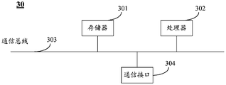
The embodiment of the present disclosure provides a system control component for controlling an integrated imaging display system as shown in any one of fig. 1 to 3, 9 and 11, as shown in fig. 13, where the system control component 30 includes: a memory 301 and a processor 302.
A memory 301 for storing a computer program;
a processor 302 for executing the program stored in the memory 301 to realize the control method of the integrated imaging display system shown in fig. 12.
Optionally, the system control element 30 further comprises a communication bus 303 and a communication interface 304.
The processor 302 includes one or more processing cores, and the processor 302 executes various functional applications and data processing by running computer programs and units.
The memory 301 may be used for storing computer programs and units. In particular, the memory may store an operating system and application program elements required for at least one function. The operating system may be a Real Time eXceptive (RTX) operating system, such as LINUX, UNIX, WINDOWS, or OS X.
The communication interface 304 may be multiple, and the communication interface 304 is used for communication with other storage devices or network devices. For example, in embodiments of the present disclosure, the communication interface 304 may be used to send control instructions to the display device and/or the polarization conversion element.
The memory 301 and the communication interface 304 are respectively connected to the processor 302 through a communication trace 303.
The disclosed embodiments provide a computer storage medium in which a program is executed by a processor, thereby implementing a control method of an integrated imaging display system as shown in fig. 12.
Alternatively, the computer storage medium may be a storage medium in a system control element (chip).
It will be understood by those skilled in the art that all or part of the steps for implementing the above embodiments may be implemented by hardware, or may be implemented by a program instructing relevant hardware, where the program may be stored in a computer-readable storage medium, and the above-mentioned storage medium may be a read-only memory, a magnetic disk or an optical disk, etc.
The above description is meant to be illustrative of alternative embodiments of the disclosure and not to limit the disclosure, and any modification, equivalent replacement, or improvement made within the spirit and principles of the disclosure should be included within the scope of the disclosure.
Claims (16)
- An integrated imaging display system, comprising: the display device comprises a display device (101), and a polarization conversion element (102), an optical path folding element (103) and a micro lens array (104) which are positioned on the light emitting side of the display device (101), wherein the polarization conversion element (102), the optical path folding element (103) and the micro lens array (104) are sequentially arranged along the direction far away from the display device (101);the polarization conversion element (102) is configured to convert light exiting the display device (101) into first linearly polarized light of a first polarization state and second linearly polarized light of a second polarization state, the first polarization state and the second polarization state being different;the optical path folding element (103) is configured to transmit the first linearly polarized light to the microlens array (104) according to a first transmission path, and transmit the second linearly polarized light to the microlens array (104) according to a second transmission path, the length of the first transmission path being greater than the length of the second transmission path;the micro-lens array (104) is configured to form a first three-dimensional display image in a first depth of field range based on the first linearly polarized light and a second three-dimensional display image in a second depth of field range based on the second linearly polarized light, wherein a first distance between a central depth of field of the first depth of field range and a light-emitting surface of the display device (101) is smaller than a second distance between the central depth of field of the second depth of field range and the light-emitting surface of the display device (101).
- The integrated imaging display system according to claim 1, wherein the microlens array (104) comprises a plurality of microlenses (1041), the optical path folding element (103) comprises a plurality of optical path folding units (1031) in one-to-one correspondence with the plurality of microlenses (1041), and orthographic projections of the optical path folding units (1031) on the light exit surface coincide with orthographic projections of the corresponding microlenses (1041) on the light exit surface;the optical path folding unit (1031) is configured to transmit the first linearly polarized light to a corresponding microlens (1041) according to the first transmission path, and transmit the second linearly polarized light to a corresponding microlens (1041) according to the second transmission path.
- The integrated imaging display system according to claim 2, wherein each of said optical path folding units (1031) comprises a polarization splitting element and two reflecting elements;the two reflecting elements are oppositely arranged, the polarization light splitting element is positioned between the two reflecting elements, and two ends of the polarization light splitting element are respectively abutted against the two reflecting elements;an included angle between a light splitting surface of the polarization light splitting element and a light incident surface of the corresponding micro lens (1041) is an acute angle, an included angle between the light splitting surface of the polarization light splitting element and a reflection surface of each reflection element is an acute angle, and the reflection surface of each reflection element is intersected with a light emergent surface of the polarization conversion element (102);the polarization beam splitter element is configured to transmit light of the first polarization state and reflect light of the second polarization state;the reflective element is configured to change a polarization state of incident light and reflect the light after the change of the polarization state.
- The integrated imaging display system according to claim 3, wherein each of said optical path folding units (1031) further comprises a transparent cuboid structure, an orthographic projection of said transparent cuboid structure on said microlens array (104) coinciding with a region of one microlens (1041);the two reflecting elements are reflecting layers respectively arranged on two opposite surfaces of the transparent cuboid structure, one end of each reflecting layer close to the microlens (1041) is abutted with the light incident surface of the corresponding microlens (1041), and the other end of each reflecting layer close to the polarization conversion element (102) is abutted with the light emergent surface of the polarization conversion element (102);the polarization beam splitting element is a polarization beam splitting film, the polarization beam splitting film is located on a diagonal plane of the transparent cuboid structure, one end of the polarization beam splitting film is abutted to one end of the reflecting layer, and the other end of the polarization beam splitting film is abutted to the other end of the reflecting layer.
- The integrated imaging display system according to claim 4, wherein said transparent cuboid structure is comprised of two triangular prism structures having said polarization splitting film disposed on rectangular faces thereof that are in contact.
- The integrated imaging display system according to claim 5, wherein said transparent cuboid structure is a transparent cube structure, said triangular prism structure is a right-angled triangular prism structure; the reflection surface of each reflection element is perpendicular to the light-emitting surface of the polarization conversion element (102).
- The integrated imaging display system according to claim 6, wherein the transparent cuboid structure and the microlenses (1041) are made of glass, and the transparent cuboid structure in each optical path folding unit (1031) is connected with the corresponding microlens (1041) through optical cement bonding.
- The integrated imaging display system according to any one of claims 4 to 7, wherein each of said reflective layers comprises a quarter-wave plate and a reflective film which are disposed in a stacked arrangement in a direction away from said polarizing beam splitting element.
- The integrated imaging display system according to claim 8, wherein the plurality of optical path folding units (1031) are arrayed in a first direction, and two optical path folding units (1031) adjacent in the first direction share one reflection film, which is a double-sided reflection film.
- The integrated imaging display system according to claim 8, wherein the plurality of optical path folding units (1031) are arrayed in a first direction, and the reflection films in two optical path folding units (1031) adjacent in the first direction are abutted.
- The integrated imaging display system according to any of claims 2 to 10, wherein said polarization converting element (102) is a polarization converting film, the orthographic projection of said polarization converting film on said display device (101) covering the display area of said display device (101);one side of the polarization conversion film is attached to the light emitting surface of the display device (101), and the other side of the polarization conversion film is attached to the light incident surface of the light path folding unit (1031).
- The integrated imaging display system according to claim 1 or 11, wherein said integrated imaging display system further comprises a system control element (105) connected to said polarization conversion element (102);the system control element (105) is configured to control the polarization conversion element (102) to convert the light emitted by the display device (101) into the first linearly polarized light in a first period of each display period, and control the polarization conversion element (102) to convert the light emitted by the display device (101) into the second linearly polarized light in a second period of each display period;wherein the duration of each display period is greater than or equal to a refresh period of the display device (101).
- The integrated imaging display system according to claim 12, wherein the duration of each display period is greater than a refresh period of the display device (101);the display device (101) is configured to display a first image during the first time period and a second image during the second time period, the depth of field of the first image being greater than the depth of field of the second image.
- The integrated imaging display system according to claim 12 or 13,the duration of each display period is less than 1/30 seconds.
- The integrated imaging display system according to claim 14, wherein said display device (101) comprises: a display panel and an image rendering element connected to the display panel and the system control element (105), respectively;the image rendering element is configured to render an image to be displayed to generate image data and send the image data to the display panel under control of the system control element (105);the display panel is configured to display an image based on the image data.
- The integrated imaging display system according to any one of claims 1 to 15, wherein said first polarization state is an S polarization state and said second polarization state is a P polarization state, said polarization splitting element configured to reflect S polarized light and transmit P polarized light.
Applications Claiming Priority (1)
| Application Number | Priority Date | Filing Date | Title |
|---|---|---|---|
| PCT/CN2019/078977 WO2020186498A1 (en) | 2019-03-21 | 2019-03-21 | Integrated imaging display system |
Publications (2)
| Publication Number | Publication Date |
|---|---|
| CN112166370A true CN112166370A (en) | 2021-01-01 |
| CN112166370B CN112166370B (en) | 2022-08-26 |
Family
ID=72518889
Family Applications (1)
| Application Number | Title | Priority Date | Filing Date |
|---|---|---|---|
| CN201980000345.8A Active CN112166370B (en) | 2019-03-21 | 2019-03-21 | Integrated imaging display system |
Country Status (4)
| Country | Link |
|---|---|
| US (1) | US11226491B2 (en) |
| EP (1) | EP3958037B1 (en) |
| CN (1) | CN112166370B (en) |
| WO (1) | WO2020186498A1 (en) |
Cited By (4)
| Publication number | Priority date | Publication date | Assignee | Title |
|---|---|---|---|---|
| CN114527581A (en) * | 2022-03-02 | 2022-05-24 | 北京京东方技术开发有限公司 | Display system and display control method thereof |
| CN114545646A (en) * | 2022-02-24 | 2022-05-27 | 四川大学 | High-resolution integrated imaging 3D display device based on retroreflector and reflective polarizer |
| WO2024051215A1 (en) * | 2022-09-09 | 2024-03-14 | 华为技术有限公司 | Three-dimensional image acquisition apparatus, and related device and method |
| CN119535808A (en) * | 2024-11-27 | 2025-02-28 | 北京颐志益德文化科技有限公司 | Imaging display device and method |
Families Citing this family (4)
| Publication number | Priority date | Publication date | Assignee | Title |
|---|---|---|---|---|
| CN112485915B (en) * | 2021-01-11 | 2024-05-10 | 深圳博瑞联三维技术有限公司 | Double-vision 3D display device based on stepped gradual change pitch polarization array |
| TWI782622B (en) * | 2021-05-21 | 2022-11-01 | 中強光電股份有限公司 | Head-up display |
| JP2022179358A (en) * | 2021-05-21 | 2022-12-02 | 中強光電股▲ふん▼有限公司 | Head-up display device |
| CN115685584B (en) * | 2021-07-21 | 2025-05-16 | 京东方科技集团股份有限公司 | Display panel, display device and display method |
Citations (6)
| Publication number | Priority date | Publication date | Assignee | Title |
|---|---|---|---|---|
| JP2005140970A (en) * | 2003-11-06 | 2005-06-02 | Nippon Hoso Kyokai <Nhk> | Stereoscopic image capturing apparatus and stereoscopic image display apparatus |
| CN101952765A (en) * | 2007-12-28 | 2011-01-19 | 3M创新有限公司 | Light combiner |
| CN106526875A (en) * | 2016-09-21 | 2017-03-22 | 南京中电熊猫液晶显示科技有限公司 | Integral imaging three dimensional display apparatus and method |
| CN107065199A (en) * | 2017-06-23 | 2017-08-18 | 舒伟 | Head-mounted display |
| CN108663807A (en) * | 2017-03-31 | 2018-10-16 | 宁波舜宇车载光学技术有限公司 | Head-up display optical system and device and its imaging method |
| CN109407315A (en) * | 2018-11-09 | 2019-03-01 | 京东方科技集团股份有限公司 | Display system and its display methods |
Family Cites Families (9)
| Publication number | Priority date | Publication date | Assignee | Title |
|---|---|---|---|---|
| GB2437553A (en) | 2006-04-28 | 2007-10-31 | Sharp Kk | Optical system with two spaced apart partial reflectors for display |
| US8421851B2 (en) * | 2010-01-04 | 2013-04-16 | Sony Corporation | Vision correction for high frame rate TVs with shutter glasses |
| KR101370050B1 (en) | 2012-06-26 | 2014-03-06 | 인텔렉추얼디스커버리 주식회사 | Depth fusedtype three dimensional image display device |
| KR101764999B1 (en) * | 2016-02-16 | 2017-08-10 | 세종대학교산학협력단 | Apparatus and Method for Controlling Location of Augmented Reality Image Using Polarization Modulator |
| WO2017164573A1 (en) * | 2016-03-23 | 2017-09-28 | Samsung Electronics Co., Ltd. | Near-eye display apparatus and near-eye display method |
| JPWO2018168626A1 (en) | 2017-03-17 | 2020-01-16 | パナソニックIpマネジメント株式会社 | Display device |
| CN108181708B (en) | 2018-01-02 | 2020-12-15 | 京东方科技集团股份有限公司 | A head-up display system and its control method |
| CN108196367A (en) * | 2018-01-18 | 2018-06-22 | 京东方科技集团股份有限公司 | Head-up-display system and its driving method |
| US20190243147A1 (en) * | 2018-02-07 | 2019-08-08 | Disney Enterprises, Inc. | Polarization-sensitive pancake optics |
-
2019
- 2019-03-21 US US16/753,361 patent/US11226491B2/en active Active
- 2019-03-21 WO PCT/CN2019/078977 patent/WO2020186498A1/en not_active Ceased
- 2019-03-21 EP EP19863990.8A patent/EP3958037B1/en active Active
- 2019-03-21 CN CN201980000345.8A patent/CN112166370B/en active Active
Patent Citations (6)
| Publication number | Priority date | Publication date | Assignee | Title |
|---|---|---|---|---|
| JP2005140970A (en) * | 2003-11-06 | 2005-06-02 | Nippon Hoso Kyokai <Nhk> | Stereoscopic image capturing apparatus and stereoscopic image display apparatus |
| CN101952765A (en) * | 2007-12-28 | 2011-01-19 | 3M创新有限公司 | Light combiner |
| CN106526875A (en) * | 2016-09-21 | 2017-03-22 | 南京中电熊猫液晶显示科技有限公司 | Integral imaging three dimensional display apparatus and method |
| CN108663807A (en) * | 2017-03-31 | 2018-10-16 | 宁波舜宇车载光学技术有限公司 | Head-up display optical system and device and its imaging method |
| CN107065199A (en) * | 2017-06-23 | 2017-08-18 | 舒伟 | Head-mounted display |
| CN109407315A (en) * | 2018-11-09 | 2019-03-01 | 京东方科技集团股份有限公司 | Display system and its display methods |
Cited By (6)
| Publication number | Priority date | Publication date | Assignee | Title |
|---|---|---|---|---|
| CN114545646A (en) * | 2022-02-24 | 2022-05-27 | 四川大学 | High-resolution integrated imaging 3D display device based on retroreflector and reflective polarizer |
| CN114545646B (en) * | 2022-02-24 | 2022-10-25 | 四川大学 | High-resolution integrated imaging 3D display device based on feedback device and reflection polarizer |
| CN114527581A (en) * | 2022-03-02 | 2022-05-24 | 北京京东方技术开发有限公司 | Display system and display control method thereof |
| CN114527581B (en) * | 2022-03-02 | 2023-09-05 | 北京京东方技术开发有限公司 | Display system and display control method thereof |
| WO2024051215A1 (en) * | 2022-09-09 | 2024-03-14 | 华为技术有限公司 | Three-dimensional image acquisition apparatus, and related device and method |
| CN119535808A (en) * | 2024-11-27 | 2025-02-28 | 北京颐志益德文化科技有限公司 | Imaging display device and method |
Also Published As
| Publication number | Publication date |
|---|---|
| EP3958037A1 (en) | 2022-02-23 |
| US11226491B2 (en) | 2022-01-18 |
| WO2020186498A1 (en) | 2020-09-24 |
| EP3958037A4 (en) | 2022-11-02 |
| CN112166370B (en) | 2022-08-26 |
| US20210215947A1 (en) | 2021-07-15 |
| EP3958037B1 (en) | 2024-06-12 |
Similar Documents
| Publication | Publication Date | Title |
|---|---|---|
| CN112166370B (en) | Integrated imaging display system | |
| CN106291958B (en) | A display device and image display method | |
| US10551627B2 (en) | 3D display device | |
| EP4130820B1 (en) | Multiple depth plane three-dimensional display using a wave guide reflector array projector | |
| US10448005B2 (en) | Stereoscopic display device and parallax image correcting method | |
| KR102447098B1 (en) | 3d display apparatus and method thereof | |
| TWI654446B (en) | Floating imaging display device | |
| US6542296B2 (en) | Back-lighted autostereoscopic display | |
| US11740535B2 (en) | Display apparatus and controlling method thereof | |
| EP2811339A2 (en) | Lens display device, liquid crystal display device and display drive method | |
| US20150370080A1 (en) | Autostereoscopic Three Dimensional Display | |
| WO2016110162A1 (en) | Near-eye display | |
| US10845614B2 (en) | Near-eye display device | |
| CN109856808A (en) | floating display device | |
| CN107278274B (en) | Directional optical waveguide, directional backlight module and display device | |
| WO2021175341A1 (en) | Display module having multiple backlight light sources | |
| CN103163651B (en) | Stereoscopic display device | |
| US9628765B2 (en) | Spatial image projection apparatus | |
| CN108333750B (en) | Near-to-eye display device | |
| US9915773B1 (en) | Backlight module and stereo display device using the same | |
| US9268077B2 (en) | Projection device | |
| US9749610B2 (en) | Spatial image projection apparatus | |
| CN110275309B (en) | Polarizing microlens structure, display device and driving method thereof | |
| CN108828774A (en) | Virtual reality shows equipment | |
| JPH11258697A (en) | Directional reflective screen and image display device |
Legal Events
| Date | Code | Title | Description |
|---|---|---|---|
| PB01 | Publication | ||
| PB01 | Publication | ||
| SE01 | Entry into force of request for substantive examination | ||
| SE01 | Entry into force of request for substantive examination | ||
| GR01 | Patent grant | ||
| GR01 | Patent grant |