CN112166318A - Electric circuit for electrochemical measurement and measuring device - Google Patents
Electric circuit for electrochemical measurement and measuring device Download PDFInfo
- Publication number
- CN112166318A CN112166318A CN201980028946.XA CN201980028946A CN112166318A CN 112166318 A CN112166318 A CN 112166318A CN 201980028946 A CN201980028946 A CN 201980028946A CN 112166318 A CN112166318 A CN 112166318A
- Authority
- CN
- China
- Prior art keywords
- circuit
- solution
- inverting input
- electrode
- capacitor
- Prior art date
- Legal status (The legal status is an assumption and is not a legal conclusion. Google has not performed a legal analysis and makes no representation as to the accuracy of the status listed.)
- Granted
Links
Images


Classifications
-
- G—PHYSICS
- G01—MEASURING; TESTING
- G01N—INVESTIGATING OR ANALYSING MATERIALS BY DETERMINING THEIR CHEMICAL OR PHYSICAL PROPERTIES
- G01N27/00—Investigating or analysing materials by the use of electric, electrochemical, or magnetic means
- G01N27/26—Investigating or analysing materials by the use of electric, electrochemical, or magnetic means by investigating electrochemical variables; by using electrolysis or electrophoresis
- G01N27/416—Systems
- G01N27/48—Systems using polarography, i.e. measuring changes in current under a slowly-varying voltage
-
- G—PHYSICS
- G01—MEASURING; TESTING
- G01N—INVESTIGATING OR ANALYSING MATERIALS BY DETERMINING THEIR CHEMICAL OR PHYSICAL PROPERTIES
- G01N27/00—Investigating or analysing materials by the use of electric, electrochemical, or magnetic means
- G01N27/26—Investigating or analysing materials by the use of electric, electrochemical, or magnetic means by investigating electrochemical variables; by using electrolysis or electrophoresis
- G01N27/416—Systems
- G01N27/4161—Systems measuring the voltage and using a constant current supply, e.g. chronopotentiometry
-
- G—PHYSICS
- G01—MEASURING; TESTING
- G01N—INVESTIGATING OR ANALYSING MATERIALS BY DETERMINING THEIR CHEMICAL OR PHYSICAL PROPERTIES
- G01N27/00—Investigating or analysing materials by the use of electric, electrochemical, or magnetic means
- G01N27/02—Investigating or analysing materials by the use of electric, electrochemical, or magnetic means by investigating impedance
- G01N27/22—Investigating or analysing materials by the use of electric, electrochemical, or magnetic means by investigating impedance by investigating capacitance
- G01N27/226—Construction of measuring vessels; Electrodes therefor
-
- G—PHYSICS
- G01—MEASURING; TESTING
- G01N—INVESTIGATING OR ANALYSING MATERIALS BY DETERMINING THEIR CHEMICAL OR PHYSICAL PROPERTIES
- G01N27/00—Investigating or analysing materials by the use of electric, electrochemical, or magnetic means
- G01N27/02—Investigating or analysing materials by the use of electric, electrochemical, or magnetic means by investigating impedance
- G01N27/22—Investigating or analysing materials by the use of electric, electrochemical, or magnetic means by investigating impedance by investigating capacitance
- G01N27/228—Circuits therefor
-
- G—PHYSICS
- G01—MEASURING; TESTING
- G01N—INVESTIGATING OR ANALYSING MATERIALS BY DETERMINING THEIR CHEMICAL OR PHYSICAL PROPERTIES
- G01N27/00—Investigating or analysing materials by the use of electric, electrochemical, or magnetic means
- G01N27/26—Investigating or analysing materials by the use of electric, electrochemical, or magnetic means by investigating electrochemical variables; by using electrolysis or electrophoresis
- G01N27/28—Electrolytic cell components
- G01N27/30—Electrodes, e.g. test electrodes; Half-cells
- G01N27/301—Reference electrodes
-
- G—PHYSICS
- G01—MEASURING; TESTING
- G01N—INVESTIGATING OR ANALYSING MATERIALS BY DETERMINING THEIR CHEMICAL OR PHYSICAL PROPERTIES
- G01N33/00—Investigating or analysing materials by specific methods not covered by groups G01N1/00 - G01N31/00
- G01N33/48—Biological material, e.g. blood, urine; Haemocytometers
- G01N33/483—Physical analysis of biological material
- G01N33/487—Physical analysis of biological material of liquid biological material
- G01N33/48707—Physical analysis of biological material of liquid biological material by electrical means
Landscapes
- Health & Medical Sciences (AREA)
- Chemical & Material Sciences (AREA)
- Life Sciences & Earth Sciences (AREA)
- Physics & Mathematics (AREA)
- General Physics & Mathematics (AREA)
- Pathology (AREA)
- Immunology (AREA)
- Analytical Chemistry (AREA)
- Biochemistry (AREA)
- General Health & Medical Sciences (AREA)
- Electrochemistry (AREA)
- Chemical Kinetics & Catalysis (AREA)
- Molecular Biology (AREA)
- Engineering & Computer Science (AREA)
- Biomedical Technology (AREA)
- Biophysics (AREA)
- Medicinal Chemistry (AREA)
- Food Science & Technology (AREA)
- Urology & Nephrology (AREA)
- Hematology (AREA)
- Investigating Or Analyzing Materials By The Use Of Electric Means (AREA)
Abstract
Provided is an electric circuit used for electrochemical measurement of a solution, comprising: a voltage generating circuit; an operational amplifier having an Output (OUT) connected to a Counter Electrode (CE) IN contact with the solution, a non-inverting input (+ IN) connected to a Reference Electrode (RE) IN contact with the solution, and an inverting input (-IN) connected to a voltage generating circuit; a capacitor connected between the Output (OUT) and the inverting input (-IN), and having a capacity of 1 [ mu ] F or more; the current measuring circuit is connected to a Working Electrode (WE) in contact with the solution.
Description
Technical Field
The present disclosure relates to an electric circuit for electrochemical measurement and a measurement device.
Background
In the electrochemical field, a chemical substance or a biological substance in a solution is detected or quantified by measuring a current flowing in the solution due to a chemical reaction or a biochemical reaction occurring at or near an electrode surface. For such measurement, for example, a three-electrode method is widely used.
The three-electrode method is a method in which a counter electrode, a reference electrode, and a working electrode are provided in a container, and a current flowing from the counter electrode to the working electrode is measured by providing a predetermined potential difference between the counter electrode and the working electrode. Generally, when a substance such as a metal or a metal oxide enters an electrolytic solution, a potential difference called an interface potential is generated between the substance and the electrolytic solution. When a voltage is applied between the counter electrode and the working electrode in consideration of this potential difference, a current flows from the counter electrode, and the potential difference between the counter electrode and the solution changes. Due to the change in the potential difference, a desired voltage may not be accurately applied to the solution. In the three-electrode method, in order to avoid this, the potential at the reference electrode is measured, and the voltage applied to the counter electrode can be controlled so that the potential is determined to be a desired value. Further, there is a feedback circuit that returns (feeds back) the potential measured at the reference electrode to a circuit that controls the counter electrode.
Disclosure of Invention
In one embodiment of the present disclosure, an electrical circuit for use in electrochemical measurement of a solution includes: a voltage generating circuit; an operational amplifier having an Output (OUT) configured to be connected to a first electrode IN contact with the solution, a non-inverting input (+ IN) configured to be connected to a second electrode IN contact with the solution, and an inverting input (-IN) connected to a voltage generating circuit; a capacitor connected between the Output (OUT) and the inverting input (-IN).
One embodiment of the present disclosure is an electrical circuit for use in electrochemical measurement of a solution. The electric circuit includes: a voltage generating circuit; an operational amplifier having an Output (OUT) connected to a Counter Electrode (CE) IN contact with the solution, a non-inverting input (+ IN) connected to a Reference Electrode (RE) IN contact with the solution, and an inverting input (-IN) connected to a voltage generating circuit; a capacitor connected between the Output (OUT) and the inverting input (-IN); the current measuring circuit is connected to a Working Electrode (WE) in contact with the solution.
One embodiment of the present disclosure is an electrical circuit for use in electrochemical measurement of a solution. The electric circuit includes: an operational amplifier having an Output (OUT) connected to a Counter Electrode (CE) IN contact with the solution, a non-inverting input (+ IN) connected to a Reference Electrode (RE) IN contact with the solution, and an inverting input (-IN) connected to a voltage generating circuit; a capacitor connected between the Output (OUT) and the inverting input (-IN); the wiring is configured to connect the Working Electrode (WE) in contact with the solution to the current measuring circuit. The voltage generating circuit may be connected to a non-inverting input (+ IN) of the operational amplifier. The current measuring circuit may be connected to a wire configured to be connected to the Working Electrode (WE).
Another embodiment of the present disclosure is an electrochemical assay device for a solution. The electrochemical measurement device is provided with: a Counter Electrode (CE) configured to be in contact with the solution; a Reference Electrode (RE) configured to be in contact with the solution; a Working Electrode (WE) configured to be in contact with the solution; a voltage generating circuit; an operational amplifier having an Output (OUT), a non-inverting input (+ IN), and an inverting input (-IN), the operational amplifier being connected to the Counter Electrode (CE) at the Output (OUT), connected to the Reference Electrode (RE) at the inverting input (-IN), and connected to the voltage generating circuit at the non-inverting input (+ IN); a capacitor connected between the Output (OUT) and the inverting input (-IN) of the operational amplifier; and a current measuring circuit connected to the Working Electrode (WE).
According to the present disclosure, the influence of noise on the measurement can be reduced, potentially or as an example, and the measurement accuracy of a minute current generated by a chemical reaction or a biochemical reaction can be improved in the electrochemical measurement in a solution.
Drawings
Fig. 1 is a circuit block diagram showing an example of the configuration of the measurement device according to the first embodiment.
Fig. 2 is a waveform diagram showing an example of a current measured without taking measures against noise.
Fig. 3 is a waveform diagram showing an example of a current measured only to take measures against external noise.
Fig. 4 is a waveform diagram showing an example of the current measured in the noise countermeasure of the first embodiment.
Fig. 5 is a waveform diagram showing an example of a current measured only to take measures against external noise.
Fig. 6 is a waveform diagram showing an example of the current measured in the noise countermeasure of the first embodiment.
Fig. 7 is a circuit block diagram showing an example of the configuration of the measuring apparatus according to the second embodiment.
Fig. 8 shows an example of a typical circuit constituting the current measuring circuit.
Fig. 9 is a circuit block diagram for explaining a mechanism of amplifying noise by the feedback circuit.
Fig. 10 is a circuit diagram illustrating the conversion of the electrical equivalent circuit.
Detailed Description
Generally, a measurement system for performing electrical measurement is affected by noise. Examples of the noise source include a commercial power supply, a switching power supply, a clock, an external device, static electricity, and a communication radio wave. The generation source of these noises can be determined. These are not built in the measurement system as in the electrode and feedback loop described below, but exist outside the measurement system. Therefore, in the present disclosure, they are collectively referred to as "external noise".
The generation source of the external noise is relatively easy to determine. Therefore, if the propagation path from the noise generation source to the measurement unit is cut off, the influence thereof can be reduced. For example, if the measurement system is covered with a shield, the influence of noise, static electricity, and communication radio waves propagated from external equipment can be greatly reduced. Further, the influence of noise caused by a commercial power supply, a switching power supply, a clock pulse, and the like entering the inside of the measurement device can be reduced by appropriately arranging the ground of the measurement device. Alternatively, the above-described noise is high in frequency except for the static electricity and the commercial power supply, and therefore can be reduced by a Low Pass Filter (LPF) or the like. The frequency of the commercial power source is determined in a country or a region, and is determined to be 50Hz or 60 Hz. Therefore, by performing averaging processing according to the cycle thereof (for example, when averaging data of 0.1 second, a 50Hz/60Hz signal becomes 0), the noise can be further reduced. Although the frequency of static electricity is not determined, countermeasures can be sufficiently taken by appropriately performing shielding in general.
On the other hand, in addition to the external noise, noise such as thermal noise, shot noise, flicker noise (1/f noise) and the like is present in the measurement device. Since these noises exist as physical phenomena in the devices, electric or electronic components in the measuring apparatus, the appropriate arrangement of the shield or the ground cannot be reduced. Further, since these noises are distributed over low frequencies, reduction by averaging processing is also difficult. In particular, flicker noise (1/f noise) is difficult to reduce by averaging because noise power increases at low frequencies.
In the electrochemical measurement, a current flowing to the working electrode due to a chemical reaction or a biochemical reaction is measured. When the concentration of the substance to be measured is low, the flowing current is very small. In such a case, if the noise is large, the amount of the substance to be measured is fixed, and the detection may not be performed. Even if quantitative determination is possible, the value after quantitative determination is sometimes extremely inaccurate.
The solution for electrochemical measurement may be a liquid extracted from a living body. The solution may be a liquid itself extracted from a living body or a liquid extracted from a human body. The liquid extracted from the living body may be a liquid or a liquid derived from the living body after the liquid is subjected to a treatment such as purification, dilution, or mixing with another liquid. The solution for performing the electrochemical measurement may be a body fluid. The body fluid may be intracellular fluid (ICF) or extracellular fluid (ECF). The body fluid may be lymph fluid, interstitial fluid, intercellular fluid, interstitial fluid, etc., or coelomic fluid, serosal fluid, pleural fluid, ascites, pericardial fluid, cerebrospinal fluid (medullary fluid), joint fluid (synovial fluid), and aqueous humor of the eye (aqueous humor). The body fluid can be digestive juice such as saliva, gastric juice, bile, pancreatic juice, intestinal juice, etc., and can also be sweat, lacrimation, nasal discharge, urine, semen, vaginal fluid, amniotic fluid, and breast milk. The solution may be a physiological buffer solution such as Phosphate Buffered Saline (PBS) or N-tris (hydroxymethyl) methyl-2-aminoethanesulfonic acid buffer (TES) containing the substance to be measured.
The solution may contain a substance to be measured. For example, the solution is tear, and the measurement target substance is glycated albumin contained in tear. Alternatively, the analyte may be glucose, albumin, glycated albumin, uric acid, glycated hemoglobin, glucose in interstitial fluid, tear glucose, albumin, urine albumin, glucose, or the like in blood or serum. The solution is not particularly limited as long as it contains a substance to be measured.
The electrochemical measurement may be amperometry at the time of electrolysis. The measurement method using electrolysis may be an amperometric method in which a current value when the potential is maintained constant is measured, or may be a method in which a change in current value when the potential is changed (voltammetry method). The electrochemical assay may be a three-electrode method.
The voltage generation circuit (voltage generator, voltage generation unit) may include a power supply, or may be configured to convert a voltage from a power supply provided outside the voltage generation circuit into a desired voltage. The voltage divider may be configured by including a circuit for dividing a power supply voltage, or may be configured by including an Integrated Circuit (IC) capable of generating a desired voltage. The voltage generation circuit may be configured by having a low-pass filter circuit and a buffer circuit.
In the present disclosure, "connected" means electrically connected unless otherwise specified. The term "connection" may be a direct connection, that is, a connection in which other electric or electronic elements or the like are not substantially interposed between the connected elements or the like, or may be an indirect connection, that is, a connection in which other electric or electronic elements or the like are interposed between the connected elements or the like, as long as the invention or the embodiment included in the present disclosure functions. For example, the Output (OUT) of the operational amplifier and the Counter Electrode (CE) may be directly connected, or a resistance of, for example, 100 Ω (ohm) may be connected in series between the Output (OUT) of the operational amplifier and the Counter Electrode (CE) in order to prevent an electronic component within the circuit from being damaged due to a connection error. Further, for example, the output of the operational amplifier may not be directly connected to the counter electrode. In one embodiment, an amplifying circuit or an attenuating circuit may be added and connected in the subsequent stage. In another embodiment, connecting multiple operational amplifiers may be used. In one embodiment, a resistor for protection may be added in series to form a connection.
IN an embodiment, a capacitor is connected between the Output (OUT) and the inverting input (-IN). The capacitor is connected at one end to the Output (OUT) and at the other end to the inverting input (-IN).
In one embodiment, the capacitor may have a capacitance of 1 μ F or more. In another embodiment, the capacitor may have a capacity greater than 1 μ F. The capacitance of the capacitor may be 2 μ F, 3 μ F, 4 μ F, 5 μ F, 6 μ F, 7 μ F, 8 μ F, 9 μ F, or 10 μ F or more, or may be a value larger than any of these values. The capacitance of the capacitor may be 10. mu.F, 20. mu.F, 30. mu.F, 40. mu.F, 50. mu.F, 60. mu.F, 70. mu.F, 80. mu.F, 90. mu.F, or 100. mu.F or more, or may be a value larger than any of these values.
In one embodiment, the capacitance of the capacitor may be larger than the capacitance of an equivalent circuit at the interface of the counter electrode during measurement. In one embodiment, the capacitor may be a noise reduction capacitor. The contact area of the electrode with the solution may be 100 mm square or less. The capacitance at the electrode interface may be generally about 10 μ F or less. The electric double layer may have a small thickness of about 1nm or more than 1 nm. For example, the electrostatic capacity of the electrode interface may be C ═ S/D ═ 70 μ F (relative permittivity of water ═ 80). Alternatively, in another example, the amount may be about several μ F. Accordingly, if the capacitance of the capacitor is 10 μ F, noise can be sufficiently reduced. Further, if the capacitance of the capacitor is 100 μ F, noise can be further reduced. For example, if the electrode area is smaller, the capacitance of the capacitor may be 0.1 μ F.
In the present disclosure, the capacity of the capacitor has no upper limit in theory, but an upper limit may be set in practice. The capacitance of the capacitor may be 100mF (millifarad), 10mF, 1mF, 500. mu.F, 400. mu.F, 300. mu.F, 200. mu.F, or 100. mu.F or less, or may be a value smaller than any of these. The capacitor may have a capacity of 350 μ F or 330 μ F.
The capacitor may be a ceramic capacitor. The capacitor may be formed by combining two or more capacitors. For example, two electrolytic capacitors may be connected in series in reverse. The capacitor may or may not have a polarity. A non-polar capacitor is useful in situations where the voltage applied to it may vary between positive and negative.
The counter electrode, the reference electrode, and the working electrode may be referred to as electrodes, or may be referred to as a counter electrode, a reference electrode, and a working electrode, respectively. At least the surface of the working electrode in contact with the solution may be formed of a metal such as platinum (Pt), gold (Au), silver (Ag), or copper (Cu), or may be a carbon electrode including carbon nanotubes, graphene, diamond, or the like, or may be a metal oxide such as tantalum oxide, or may be a conductive polymer. At least the surface of the counter electrode in contact with the solution may be formed of a metal such as platinum (Pt), gold (Au), silver (Ag), or copper (Cu), or may be formed of a carbon electrode, a conductive polymer, or the like. At least the surface of the reference electrode that is in contact with the solution may be formed of silver/silver chloride (Ag/AgCl), a saturated KCl salt bridge, mercury (Hg), mercury chloride (HgCl), a standard hydrogen electrode, or the like. These materials are examples, and the raw material of the electrode of the present disclosure is not particularly limited.
The current measuring circuit may have a current-voltage converting circuit. In one embodiment, the current measuring circuit may be configured by connecting a current-voltage converting circuit in series with the voltage measuring circuit. In one embodiment, the voltage measuring circuit may be an a/D converter.
In general, in an electric circuit, points at which a plurality of circuit elements or wirings are connected are represented by dots called black circles called nodes or nodes (nodes). In the present disclosure, however, the above-described node or node and a portion other than the electrical and electronic circuit or element explicitly shown, such as a wiring portion which can be handled with substantially the same electric potential in the circuit function, are collectively referred to as a node.
Hereinafter, embodiments of the present invention will be described in detail with reference to the drawings. In the drawings for describing the embodiments, the same components are denoted by the same reference numerals in principle, and redundant description thereof will be omitted.
< first embodiment >
< construction of measuring apparatus >
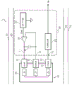
Fig. 1 is a circuit block diagram showing a configuration of a measurement device according to an embodiment (first embodiment) of the present disclosure. The measuring apparatus 1 is an apparatus for performing electrochemical measurement of a solution. The measuring apparatus 1 may detect and quantify a substance to be measured in a solution. The measurement device 1 shown in fig. 1 includes an electric circuit 10, a container 90 for containing a solution, a counter electrode 91 disposed in the container 90 and in contact with the solution 95 during measurement, a reference electrode 92, and a working electrode 93. The electric circuit 10 includes a voltage generating circuit (voltage generating unit, voltage generator) 20, an operational amplifier 30, a capacitor 40, and a current measuring circuit (current measuring unit, current measuring device) 50. The voltage generating circuit 20, the operational amplifier 30, the capacitor 40, and the current measuring circuit 50 are formed partially or entirely on a substrate (not shown). In one embodiment, the substrate may be a substrate made of a material such as paper phenolic, glass epoxy, or the like.
The output of the voltage generation circuit 20 is connected to the non-inverting input (+ IN) of the operational amplifier 30, and supplies the reference voltage Vref. The voltage generation circuit 20 supplies an output signal having a stable potential difference Vref to the ground potential of the measurement device 1.
The Output (OUT) of the operational amplifier 30 is connected to the counter electrode 91, and the inverting input (-IN) is connected to the reference electrode 92. The capacitor 40 is connected between the counter electrode 91 and the reference electrode 92, or between the Output (OUT) and the inverting input (-IN) of the operational amplifier 30. IN other words, the capacitor 40 is connected at one end to the Output (OUT) of the operational amplifier 30 and the counter electrode 91, and at the other end to the inverting input (-IN) of the operational amplifier 30 and the reference electrode 92.
The current measuring circuit 50 is connected to the working electrode 93, and receives a value of the current from the working electrode 93 to output an output signal to the outside of the electric circuit 10.
A wiring portion having substantially the same potential between the Output (OUT) of the operational amplifier 30 and the capacitor 40 or between the Output (OUT) of the operational amplifier 30, the capacitor 40, and the counter electrode 91 is referred to as a node (first node) 11. A wiring portion having substantially the same potential between the inverting input (-IN) of the operational amplifier 30 and the capacitor 40, or between the inverting input (-IN) of the operational amplifier 30, the capacitor 40, and the reference electrode 92 is referred to as a junction (second junction) 12. A wiring portion of substantially equal potential between the working electrode 93 and the current measuring circuit is referred to as a node (third node) 13.
In one embodiment, the container 90 for containing the solution 95, the counter electrode 91, the reference electrode 92, and the working electrode 93 are configured to be detachable from the measurement device 1. The container 90 for containing the solution 95, the counter electrode 91, the reference electrode 92, and the working electrode 93 can be disposable for each measurement according to the frequency of use and the time interval. In one embodiment, the measurement device 1 may be configured such that the container 90 for storing the solution, the counter electrode 91, the reference electrode 92, and the working electrode 93 are inserted, and the counter electrode 91, the reference electrode 92, and the working electrode 93 are in electrical contact with the first junction 11, the second junction 12, and the third junction 13, respectively. In another embodiment, the container 90 for holding the solution, the counter electrode 91, the reference electrode 92, and the working electrode 93 may be formed or manufactured integrally with the measurement device 1.
In fig. 1, the measurement device 1 includes a shield 60. The shield 60 can reduce external noise. In fig. 1, the shield 60 is disposed so as to surround the electric circuit 10, the container 90, the counter electrode 91, the reference electrode 92, and the working electrode 93, and the disposition of the shield 60 is not limited to this. The shield 60 may be disposed along or around the second node 12.
The first to third nodes 11 to 13 may be disposed on the substrate. The shield 60 may be made of metal or conductive material. The shield 60 may be connected to the ground potential of the measurement device 1. In one embodiment, the nodes connected to the counter electrode, the reference electrode, and the working electrode may be partially or entirely formed by coaxial cables (not shown). The inner conductor of the coaxial cable may be connected to each electrode as wiring of each node, and the outer conductor may be connected to the shield 60. When the node is physically long, external noise picked up by the node can be reduced. In one embodiment, the coaxial cable is configured to connect the electrical circuit and the electrodes via a detachable connector (not shown). In the present disclosure, the form of connection of the first junction 11, the second junction 12, and the third junction 13 of the measurement device 1 to the counter electrode 91, the reference electrode 92, and the working electrode 93 is not limited.
IN one embodiment, the wirings connected to the Output (OUT) of the operational amplifier 30, the inverting input (-IN) of the operational amplifier 30, and the current measurement circuit 50 may be connected to the counter electrode 91(CE), the reference electrode 92(RE), and the working electrode 93(WE) that are IN contact with the solution during electrochemical measurement. In one embodiment, the measuring apparatus 1 and the electric circuit 10 may be configured such that a member including an electric circuit and a member including the Counter Electrode (CE), the Reference Electrode (RE), and the Working Electrode (WE) are brought into contact or combined with each other by mechanical embedding or the like, thereby electrically contacting the counter electrode 91(CE), the reference electrode 92(RE), and the working electrode 93(WE) with the respective wirings.
In one embodiment, the container 90 for containing the solution 95 may be configured to be detachable from the measurement device 1 in a cassette form. The container 90 may have an inlet for introducing the solution 95 or another liquid. The container 90 may have a drain for draining the solution 95 or other liquid. The inlet and the outlet may be one or more, respectively, and may be formed as the same hole. In one embodiment, the counter electrode 91(CE), the reference electrode 92(RE), and the working electrode 93(WE) may be fixed to the container 90, or may be detachably fixed to the container 90. In one embodiment, the container 90 may be configured to contain the solution 95 in a state in which it does not substantially flow during measurement. In another embodiment, the container 90 may be configured as a flow path.
The measurement device 1 shown in fig. 1 includes a housing 70. In one embodiment, the housing 70 may be configured to house or support the container 90 and the electrical circuit 10. The measuring apparatus 1 may be a table-top type apparatus or a portable (portable) type apparatus.
In the measurement, the solution 95 is introduced into the container 90 from an introduction part or an inlet (not shown).
The substance to be measured or the substance to be measured may be contained in the solution in advance, or may be mixed with the solution 95 at a different timing after introducing a solution not containing the substance to be measured into the container 90. The timing of mixing the measurement target substance and the solution is not limited to this. For example, in one embodiment, the solution 95 in which the substance to be measured is dissolved may be injected into the container 90 from a state in which the counter electrode 91, the reference electrode 92, and the working electrode 93 are not in contact with the solution 95, that is, a dry state. In another embodiment, a solution containing no substance to be measured may be introduced into the container 90, and the counter electrode 91, the reference electrode 92, and the working electrode 93 may be immersed and then replaced with a solution in which the substance to be measured is dissolved. In another embodiment, the counter electrode 91, the reference electrode 92, and the working electrode 93 may be immersed in a solution containing no substance to be measured in advance, and the substance to be measured may be dissolved in the solution in the container 90. In still another embodiment, the counter electrode 91, the reference electrode 92, and the working electrode 93 may be immersed in a solution containing no substance to be measured in advance, and the sample to be measured containing the substance to be measured may be dissolved in the solution.
The introduced solution 95 is in contact with at least a part of the surfaces of the counter electrode 91, the reference electrode 92, and the working electrode 93. When a voltage is supplied from the voltage generator 20, a feedback loop is formed from the output of the operational amplifier 30 via the first node 11, the counter electrode 91, the solution 95, the reference electrode 92, the second node 12 and back to the inverting input (-IN) of the operational amplifier 30 again. By this feedback loop, the voltage of the counter electrode 91 is controlled so that the voltage transmitted from the reference electrode 92 to the second node 12 becomes equal to the reference voltage Vref. The operational amplifier 30 is one constituent element of the feedback circuit, but in another embodiment, other circuit components having the same function may be used.
The capacitor 40 can reduce the influence of noise (hereinafter referred to as "physical noise") inherent in the components of the device, such as thermal noise, shot noise, and flicker noise.
In the feedback circuit shown in fig. 1, physical noise is present in the components of the voltage generating circuit 20 or the operational amplifier 30. Physical noise inherent IN components of the voltage generation circuit 20 is superimposed on the reference voltage signal as voltage noise, and is input to the non-inverting input terminal (+ IN) of the operational amplifier 30. The physical noise inherent IN the operational amplifier 30 exists IN both the inverting input (-IN) and the non-inverting input (+ IN), but can be equivalently calculated as the sum thereof existing collectively at the non-inverting input (+ IN) of the operational amplifier 30. The noise of the operational amplifier 30 overlaps with the reference voltage signal. Thus, the physical noise existing IN various places can be considered as one noise which is superimposed on the reference voltage Vref and collected at the non-inverting input (+ IN) of the operational amplifier 30. Hereinafter, this is expressed as "pooled physical noise".
Here, the physical properties and electrical properties of the interface between the electrode and the solution are briefly described. The interface of the electrode with the solution is surrounded by a complex phenomenon. When an alternating voltage is applied to the interface, a current corresponding thereto flows, and thus the impedance of the interface can be defined by its ratio. Which is referred to in this disclosure as the interface impedance. What constitutes the interface impedance are the redox reaction and the electric double layer. The redox reaction causes transfer of electrons between the solution and the electrode, and thus direct current flows. The electric double layer is formed by ions concentrated on the interface, and does not generate the connection of electrons. However, if the potential of the electrode changes, the ion concentration distribution in the solution changes, and the state of the electrons of the electrode changes in response to the change, and this is detected as an alternating current. This makes it possible to electrically express the redox reaction as a resistance and the electric double layer as a capacitor. Therefore, the interface impedances can be approximately expressed as their parallel circuits. Further, the interface has a complicated element such as a wobber resistance which is governed by the diffusion rate. However, these do not have a large influence on the present disclosure, and thus, description is omitted. The counter electrode 91, the reference electrode 92, and the working electrode 93 each have an interface impedance, and each can be expressed approximately as a parallel circuit of a resistance and a capacitance.
The pooled physical noise is amplified by a feedback loop. The mechanism is explained below. The feedback amount from the operational amplifier output to the inverting input is determined by impedance division Zw/(Zc + Zw) of the interface impedance Zc between the counter electrode 91 and the solution 95 and the interface impedance Zw between the working electrode 93 and the solution 95.
Actually, there is a path of impedance Zr of an equivalent circuit via the interface of the reference electrode 92 and the solution 95. However, since the input impedance of the inverting input (-IN) of the operational amplifier 30 at the front thereof is sufficiently large, it is considered that the impedance Zr of the reference electrode 92 does not affect the impedance division of the feedback path. In addition, the input impedance of a typical operational amplifier is much larger than the values of Zc and Zw that are actually obtained. The input impedance of the current measuring circuit 50 may be considered to be sufficiently small. This is because a low input impedance of the ammeter is an essential condition. For example, in the current measuring circuit 50 shown in fig. 8, the current-voltage converting circuit 51 is assumed to be grounded through the input portion, and the input impedance can be regarded as 0.
When looking at fig. 9 in which the equivalent impedances Zc, Zw of the operational amplifier 30, the counter electrode 91, and the working electrode 93, and only the input of the current measuring circuit 50 serving as a virtual ground are modeled, the arrangement of the feedback circuit constitutes a typical non-inverting amplifier. Therefore, it is considered that the physical noise collected to the non-inverting input (+ IN) of the operational amplifier 30 is amplified by (Zc + Zw)/Zw and appears at the output of the operational amplifier 30 as it is through the first node 11 to appear at the counter electrode 91.
In electrochemical measurements such as the three-electrode method, a current generated by a chemical reaction or a biochemical reaction of a substance contained in a solution in a minute amount is measured. In order to obtain more current, it is effective to increase the contact area of the working electrode with the solution. Generally, the area of the working electrode is larger than the area of the electrode. When the contact area is large, the impedance of the interface decreases and the electrostatic capacity increases.
The following is considered specifically by calculation. For example, when the results were obtained by the examples, the area of the working electrode was about 2.5 times the area of the counter electrode, and the equivalent circuits of the interfaces of the counter electrode, the reference electrode, and the working electrode were 35 M.OMEGA./2.8. mu.F, 2 M.OMEGA./1.4. mu.F, and 14 M.OMEGA./7. mu.F, respectively. Here, "/" indicates that the right and left elements are connected in parallel.
Considering the rate of the chemical reaction, the time required for the measurement is about 0.1 second to about 1 minute, and the frequency is in the range of about 0.01Hz (Hertz) to 10 Hz. In this frequency band, the capacitance is dominant in an equivalent circuit of the interface, and therefore the impedance is substantially proportional to the reciprocal of the capacitance. When the input impedance of the inverting input (-IN) of the operational amplifier 30 is sufficiently large, Zr can be ignored IN the absence of the capacitor 40, and the amplification factor of noise IN the feedback loop can be expressed as (Zc + Zw)/Zw.
In the above case, the ratio of the impedance Zc of the counter electrode 91 to the impedance Zw of the working electrode 93 is calculated as Zc/Zw ≈ (1/Cc)/(1/Cw) ═ Cw/Cc ═ 7 μ F/2.8 μ F ═ 2.5. Therefore, the amplification factor of noise in the feedback loop when the capacitor 40 is not present is (Zc + Zw)/Zw ═ 1+2.5)/1 ═ 3.5.
IN the present disclosure, the capacitor 40 is connected to the first node 11, which is the output of the operational amplifier 30, and the second node 12, which is the inverting input (-IN) of the operational amplifier 30. The capacitor 40 is disposed IN parallel IN the feedback loop on a path returning from the first node 11, which is the Output (OUT) of the operational amplifier 30, to the second node 12, which is the inverting input (-IN) of the operational amplifier 30, via the counter electrode 91, the solution 95, and the reference electrode 92. Therefore, the amount of return of the feedback loop increases as compared to when the capacitor 40 is not present. This reduces the noise power appearing on the counter electrode 91 via the first node 11, and can improve the measurement accuracy of the minute current.
The case where the amplification factor of noise decreases when the return amount of the feedback loop increases can be understood in consideration of the following. First, the connection of Zc, Zr and the impedance Zn of the capacitor 40 is made as a pi-type connection (fig. 10A), and is converted into a T-type connection (fig. 10B). More specifically, the π -type connection of Zc, Zr, Zn shown in FIG. 10C can be converted to the T-type connection of Z1, Z2, Z3 shown in FIG. 10D. In this case, Z1 ═ Zr × Zn)/(Zr + Zn + Zc), Z2 ═ Zr × Zc)/(Zr + Zn + Zc, and Z3 ═ Zn × Zr)/(Zr + Zn + Zc can be expressed. The T-junctions Z1, Z2, Z3 shown in fig. 10B may also behave similarly. In this case, if the operational amplifier 30 is disposed and the input impedance of the operational amplifier 30 is sufficiently large, Z3 can be ignored, and therefore, the return amount of the feedback loop can be expressed as (Z2+ Zw)/(Z1+ Z2+ Zw) and the amplification factor of the noise can be expressed as (Z1+ Z2+ Zw)/(Z2+ Zw). Here, when the impedance Zn of the capacitor 40 is much smaller than the impedance Zc of the counter electrode 91, since Z2> > Z1, the amplification factor of noise becomes (Z1+ Z2+ Zw)/(Z2+ Zw) ≈ Z2+ Zw)/(Z2+ Zw) ═ 1. Alternatively, since the amplification of the non-inverting amplifier constituted by the feedback loop is reduced, it can be understood that the amplification of the physical noise collected present at the non-inverting input (+ IN) of the operational amplifier 30 is reduced.
When the capacitance Cn of the capacitor 40 is larger than the capacitance Cc of the interface of the counter electrode 91, the return amount increases. For example, if the capacitance Cc, Cw of the counter electrode 91 and the working electrode 93 described above is used as it is and the capacitance Cn of the capacitor 40 is set to 100 μ F, most of the return is performed by the capacitor 40, and therefore the return amount becomes substantially 1 and the noise is not amplified. That is, a 3.5 times reduction in noise is brought about as compared with the case where the capacitor 40 is not present.
Noise generated by external noise having a relatively high frequency can be reduced by averaging processing in accordance with measures against the shield and the ground. However, noise with a relatively low frequency cannot be expected to be reduced by a technique such as averaging. For example, physical noise is inherent in the component and therefore cannot be reduced by the shield or ground. In addition, if the low-frequency physical noise is to be reduced by averaging, the original signal is also reduced. Among the physical noises, flicker noise which increases in inverse proportion to the frequency is dominant noise at low frequencies. Flicker noise in the vicinity of the time constant of the electrochemical reaction is very difficult to remove by conventional methods.
In contrast, the electric circuit having the capacitor 40 and the feedback circuit thereof can significantly improve the effect of noise reduction in a frequency range of, for example, about 0.01Hz to 10 Hz. Alternatively, the electric circuit having the capacitor 40 and the feedback circuit thereof can increase the amount of return of noise having a frequency of, for example, about 0.01Hz to 10Hz, and therefore amplification of noise in the feedback circuit can be suppressed. In the electrochemical measurement, the chemical reaction may take about 0.1 second to 1 minute or more. Accordingly, the electrical circuit of the present disclosure including the capacitor 40 can improve the accuracy of the electrochemical measurement.
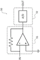
As shown in fig. 8, the current measuring circuit 50 may include a current-voltage converting circuit 51. In one embodiment, the current-voltage conversion circuit 51 may be configured by using an operational amplifier and a resistor. At this time, the inverting input of the operational amplifier becomes a virtual ground. The input impedance of the third junction 13 is low and can be considered as 0. The measuring apparatus 1 may have an analog-to-digital (a/D) conversion circuit 52 inside (fig. 8) or outside the current-to-voltage conversion circuit 50. In the current measuring circuit 50 shown in fig. 8, the current signal from the working electrode 93 is subjected to current-voltage conversion by the current-voltage conversion circuit 51, converted into digital data by the a/D converter 52, and output to the outside of the electric circuit 10 as a digital signal.
The counter electrode 91 is an electrode having a predetermined voltage difference with the working electrode 93. The voltage difference can be determined according to the type of electrode used for measurement or the substance to be measured. In one embodiment, when a molecule recognition film is provided on an electrode or an electrode surface, a voltage as high as possible can be applied to the molecule recognition film in a range where an excessive load does not act. The potential difference between the counter electrode 91 and the solution 95 changes according to the amount of current flowing. Therefore, in order to maintain the potential of the solution 95 at a predetermined value, the potential of the solution is measured by the reference electrode 92, and the potential of the counter electrode 91 is controlled by a feedback circuit.
In one embodiment, a molecular recognition membrane (not shown) that specifically reacts with a substance to be measured is provided on the surface of the working electrode 93. The molecular recognition film may comprise a polymeric film. The Polymer film may be, for example, a Polymer film such as a biomolecule of an antigen, an antibody, an enzyme, etc., a Self-Assembled Monolayer (SAM), a Molecular Immobilized Polymer (MIP), etc., depending on the substance to be measured. In an environment where a voltage is applied from the counter electrode 91, if the molecule recognition film reacts with the substance to be measured, a current is generated. For example, when a substance to be measured is decomposed in a molecular recognition film, it is considered that a current is generated by transfer of electrons by oxidation-reduction or the like. When the substance to be measured is bound to the molecular recognition film, it is considered that a current is generated due to a change in surface charge. It is considered that some change in the substance to be measured in the molecular recognition film is detected as an electrical signal by the working electrode. The above mechanism is an example and is assumed, and the present disclosure is not limited thereto, and other mechanisms may be used.
The shield 60 is made of a conductive material containing metal, for example. In one embodiment, the shield 60 can block noise entering from outside the device. In one embodiment, noise generated in an internal circuit such as commercial power supply noise and switching noise can be reduced by setting the shield to the same potential as the ground potential.
During measurement, the voltage generation circuit 20 generates a reference voltage Vref and supplies the reference voltage Vref to the operational amplifier 30. The operational amplifier 30 controls the output voltage so that the reference electrode 92 becomes the reference voltage Vref. In the working electrode 93, a chemical reaction occurs.
< example 1>
Here, one embodiment included in the present disclosure is explained. As the counter electrode 91, a platinum electrode having an area of about 4 mm square was used. As the working electrode 93, a platinum electrode of about 10 square mm was used, and a fructose amino acid oxidation (FAOD) enzyme membrane for assaying glycated albumin was formed on the surface thereof. As the reference electrode 92, a platinum electrode of about 2 square mm was used, and silver chloride was disposed on the surface thereof.
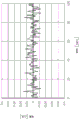
The measurement was performed in a state where three electrodes were immersed in a 300mM tris (hydroxymethyl) aminomethane sulfonic acid (TES) solution as a good buffer under a voltage of 450mV applied between the counter electrode 91 and the working electrode 93. The noise waveforms at this time are shown in fig. 2, 3, and 4. Fig. 2 shows a noise waveform measured without implementing the noise countermeasure of the present disclosure. Fig. 3 shows a noise waveform when a countermeasure for reducing external noise is implemented by performing shielding, appropriate ground line arrangement, or the like. Fig. 4 shows a noise waveform when a capacitor configured with 10 μ F is used as the capacitor 40 of the present disclosure.
As shown in fig. 2, in the case where the noise countermeasure is not implemented, noise of a degree of 0.7nA (nanoamp) p-p (peak t o peak) is observed. As shown in fig. 3, when the countermeasure for reducing the external noise is implemented, a noise of about 0.12nAp-p is observed. The influence of external noise substantially disappears, and the observed noise is dominated by physical noise. However, an amplification effect in the feedback loop is observed. As shown in fig. 4, when an electric circuit including a noise reduction capacitor is used, the noise is reduced to about 0.04 nAp-p. It was confirmed that the amplification effect of the noise was reduced.
Next, another embodiment included in the present disclosure is explained.
< example 2>
In this example, TES not containing glycated albumin was introduced into container 90, immersed in counter electrode 91, reference electrode 92 and working electrode 93, and then replaced (exchanged) with TES containing 1mg/mL of glycated albumin dissolved therein. Fig. 5 and 6 show the current waveforms measured under the same conditions as in example 1 for this solution. Fig. 5 shows an example of a current waveform when measures for reducing external noise are taken by performing shielding, appropriate ground line arrangement, or the like. Fig. 6 shows a current waveform when a capacitor of 10 μ F is provided as the capacitor 40.
In each of the graphs of fig. 5 and 6, the solution was replaced at the time points of 28 seconds and 32 seconds. When the solution is replaced, the current value sharply increases (in these figures, the downward direction of the graph means an increase in current due to the relation of the measurement system). Then, when the time reaches around 80 seconds, the current is stabilized. Such a peak current is considered to occur due to factors other than the desired chemical reaction, such as formation of an electric double layer and variation in ion concentration distribution in the solution. It is difficult to measure the current corresponding to the chemical reaction to be measured due to the peak current. Therefore, it is preferable to measure a stable current after the peak current or the abrupt change in current disappears.
For example, about 10. mu.L of tear contains glycated albumin at a concentration of about 1 mg/mL. Therefore, in the quantification of glycated albumin in tears, it is required to accurately measure the current to such an extent. The current value is about 5-10 nA when the current value is stable. It is required to measure this value with an accuracy of 1% unit, i.e., an accuracy of about 0.05nA to 0.1 nA. In the measurement of fig. 5, it is almost impossible to ensure an accuracy of 1% of the current value. On the other hand, in the measurement of fig. 6, the influence of noise can be reduced to 1% or less. Furthermore, time averaging may be used. This can further improve the measurement accuracy.
As in the case of this embodiment, if the substance to be measured is added to the solution not containing the substance to be measured, the current flowing from the counter electrode to the working electrode changes, and the potential of the counter electrode 91 changes in response to this change. The potential of the reference electrode 92 is constant, and therefore the potential difference applied to both ends of the capacitor 40 varies. Since this change requires charge injection, the capacitor 40 needs to be charged during measurement. At this time, the charge injected into the capacitor 40 passes from the reference electrode 92 only through the second junction 12. The current injected from reference electrode 92 is limited by the resistance of reference electrode 92. That is, the injection time of the charge into the capacitor 40 is determined by the resistance of the reference electrode 92 and the capacitance of the capacitor 40.
For example, when the capacitance of the capacitor 40 is 10 μ F and the resistance of the reference electrode 92 is about 2M Ω as in the present example, the time constant of charging the capacitor 40 is 20 seconds. Therefore, this configuration can exhibit an effect of suppressing noise, and can avoid or reduce a case where the waiting time for charging the capacitor 40 greatly hinders the measurement. In other words, the improvement of the measurement accuracy of the minute current and the suppression of the measurement time can be achieved at the same time.
In another embodiment, the capacitor 40 may have a capacity of 100 μ F or more. The impedance Zn of the capacitor 40 becomes smaller, the return amount of noise is further increased, and the amplification of noise can be further suppressed. This can further improve the measurement accuracy of the minute current.
< second embodiment >
Next, another embodiment (second embodiment) of the present disclosure will be described with reference to fig. 7. Hereinafter, description of the portions overlapping with the above-described embodiment will be omitted in principle.
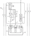
Fig. 7 is a circuit block diagram showing an example of the configuration of the measuring apparatus according to the second embodiment. The measurement device 101 shown in fig. 7 includes an electric circuit 110, a container 90 for containing a solution 95, a counter electrode 91, a reference electrode 92, a working electrode 93, a shield 60, and a housing 70. The electric circuit 110 includes a voltage generating circuit 20, an operational amplifier 30, a capacitor 40, a switch (switching circuit) 180, and a buffer circuit 181. In one embodiment, the electric circuit 110 may include a voltage generating circuit 20, an operational amplifier 30, a capacitor 40, a current measuring circuit 50, and a capacitor charging circuit (not shown). The time for which the capacitor charging circuit charges the capacitor 40 may be less than or equal to any one of 1 second, 5 seconds, 10 seconds, 30 seconds, 1 minute, 2 minutes, 3 minutes, 4 minutes, 5 minutes, 10 minutes, 15 minutes, 30 minutes, and 60 minutes.
The capacitor 40 shown in fig. 7 is arranged between the first node 11 and the switch 180. That is, the capacitor 40 is connected at one end to the Output (OUT) of the operational amplifier and the first node 11, and at the other end to the output terminal 180c of the switch circuit 180.
The switch 180 is a circuit block including a first input terminal 180a, a second input terminal 180b, and an output terminal 180 c. The switch 180 includes a control unit (not shown) that can switch the connection of the two input terminals. The first input terminal 180a is connected to the output terminal of the buffer circuit 181. The second input terminal 180b is connected to the inverting input (-IN) of the operational amplifier 30 and the reference electrode 92, i.e., to the second node 12. The output terminal 180c is connected to one terminal of the capacitor 40. The switch 180 can switch the connection destination of the capacitor 40 by switching the connection of the input terminals.
The buffer circuit 181 is a circuit that receives an input voltage with a high impedance and outputs the same voltage as the input voltage with a low impedance. The buffer circuit 181 shown in fig. 7 is connected at an output terminal to the first input terminal 180a of the switch circuit 180. The input terminals are connected to the inverting input (-IN) and to the reference electrode 92, i.e. to the second junction 12. The buffer circuit 181 is capable of receiving the voltage of the reference electrode 92 and the second node 12 with high impedance and charging the capacitor 40 with low impedance when the switch 180 is connected through the first input terminal 180 a. The buffer circuit 181 may be a voltage follower using an operational amplifier. However, the buffer circuit 181 is not limited thereto, and may be of a different structure.
The capacitance of the capacitor 40 may be larger than the interface capacitance of the counter electrode 91 and the interface capacitance of the reference electrode 92. In this case, the charging time of the capacitor 40 may be longer than the time until the chemical reaction becomes stable. There are also cases where the capacitor 40 delays the progress of the chemical reaction. The electrochemical measurement cannot be performed correctly while the capacitor 40 is charged. Therefore, the period during which the capacitor 40 is charged becomes a waiting time. Therefore, the measurement time needs to be set to be longer than the case where the capacitor 40 does not exist, in other words, the measurement time needs to be set to be sufficiently long to protect the waiting time for charging the capacitor 40. For example, when the capacitance of the capacitor 40 is 10 μ F or 100 μ F and the resistance component at the interface of the reference electrode 92 is 2M Ω (mega ohm), the time constants calculated as simple CR products are 20 seconds or 200 seconds, respectively. These time constants have the potential to affect chemical and biochemical reactions.
Further, the reduction in the amplification factor of noise is in a negative relationship with the minimization of the influence on the reaction or the shortening of the measurement time. Therefore, even in the optimized configuration, both the noise reduction effect and the measurement time are sacrificed little by little. The capacity of the optimal noise reduction capacitor varies depending on the electrode used. For example, the electrode to be used may be different depending on the substance to be measured, the electrode to be used, the molecular recognition membrane, the solution to be measured, the concentration of the substance to be measured in the solution, and the concentration to be measured, and therefore, the noise reduction capacitor needs to be replaced.
In contrast, the following effects are potentially exhibited by the electric circuit 110 having the buffer circuit 181 and the switch 180 as in the present embodiment. That is, before the chemical reaction becomes stable, that is, during the waiting time before the start of measurement, the output terminal 180c of the switch 180 is connected to the input terminal 180a by a signal from the control unit. Thereby, the switch 180 connects the capacitor 40 to the output terminal of the buffer circuit 181. Therefore, the capacitor 40 can be rapidly charged to a predetermined voltage by the configuration of the electric circuit including the buffer circuit 181 before the chemical reaction is stabilized. During charging, the capacitor 40 does not form a component of the feedback loop, and therefore does not affect the chemical reaction or biochemical reaction, nor the convergence time of the feedback circuit. In one embodiment, the output impedance of the buffer circuit 181 may be 1 Ω or less, and thus the charging time of the capacitor 40 may be 100 μ sec (microseconds) or less. For example, in the embodiment shown in fig. 5 or fig. 6, the chemical reaction subsides around 1 minute. In such a case, if the charging time is set to about 1 second to several seconds, it does not cause a significant problem in the measurement. When the chemical reaction subsides in about 5 seconds, the time constant of the circuit may be set to 100msec (milliseconds).
When the chemical reaction becomes stable, the control section switches the switch 180 to connect the capacitor 40 to the second node 12. At this time, the capacitor 40 is charged to the same voltage as the voltage of the second node 12 through the buffer circuit 181. Therefore, it is not necessary to reconverge the feedback circuit by switching, and noise reduction at the time of measurement is exhibited as one effect.
The present disclosure includes, without limitation, the following embodiments:
1. an electric circuit used for electrochemical measurement of a solution, comprising:
a voltage generating circuit;
an operational amplifier having an Output (OUT), a non-inverting input (+ IN), and an inverting input (-IN),
the Output (OUT) is configured to be connected to a Counter Electrode (CE) in contact with the solution,
the inverting input (-IN) is configured to be connected to a Reference Electrode (RE) IN contact with the solution,
the non-inverting input (+ IN) is connected to the voltage generating circuit;
a capacitor connected between the Output (OUT) and the inverting input (-IN), and having a capacity of 1 [ mu ] F or more; and
and a current measuring circuit connected to a Working Electrode (WE) in contact with the solution.
2. The electrical circuit of embodiment 1, wherein,
the capacitor has a capacity of 10 [ mu ] F or more.
3. The electrical circuit of embodiment 2, wherein,
the capacitor has a capacity of 100 [ mu ] F or more.
4. The electrical circuit according to any one of embodiments 1 to 3, wherein,
the capacitance of the capacitor is larger than the capacitance of an equivalent circuit at the interface of the counter electrode during measurement.
5. An electric circuit used for electrochemical measurement of a solution, comprising:
a voltage generating circuit;
a current measurement circuit configured to be connected to a Working Electrode (WE) in contact with the solution;
an operational amplifier having an Output (OUT), a non-inverting input (+ IN), and an inverting input (-IN),
the Output (OUT) is configured to be connected to a Counter Electrode (CE) in contact with the solution,
the inverting input (-IN) is configured to be connected to a Reference Electrode (RE) IN contact with the solution,
the non-inverting input (+ IN) is connected to the voltage generating circuit;
a capacitor having a capacity of 1 μ F or more;
a switching circuit having a first input terminal, a second input terminal, and an output terminal; and
a buffer circuit having an input terminal and an output terminal,
said capacitor being connected at one end to the Output (OUT) of said operational amplifier and at the other end to the output of said switching circuit,
the switching circuit is connected at a first input terminal to the output terminal of the buffer circuit and at a second input terminal between the output terminal and the inverting input (-IN) of the operational amplifier,
the buffer circuit is connected at an input terminal between the input terminal and an inverting input (-IN) of the operational amplifier.
6. An electrochemical measurement device for a solution, comprising:
a Counter Electrode (CE) configured to be in contact with the solution;
a Reference Electrode (RE) configured to be in contact with the solution;
a Working Electrode (WE) configured to be in contact with the solution;
a voltage generating circuit;
an operational amplifier having an Output (OUT), a non-inverting input (+ IN), and an inverting input (-IN),
is connected to the Counter Electrode (CE) at the Output (OUT),
connected to the Reference Electrode (RE) at the inverting input (-IN),
is connected to the voltage generating circuit at the non-inverting input (+ IN);
a capacitor connected between the Output (OUT) and the inverting input (-IN) of the operational amplifier, and having a capacity of 1 μ F or more; and
a current measuring circuit connected to the Working Electrode (WE).
7. The electrochemical measuring device according to embodiment 6, wherein,
the solution contains a substance to be measured,
the electrochemical measurement device further includes a molecule recognition film that is provided at least on a surface of the working electrode that is in contact with the solution and that specifically reacts with the measurement target substance.
8. An electrochemical measurement device for a solution, comprising:
a Counter Electrode (CE) configured to be in contact with the solution;
a Reference Electrode (RE) configured to be in contact with the solution;
a Working Electrode (WE) configured to be in contact with the solution;
a voltage generating circuit;
a current measuring circuit connected to the Working Electrode (WE);
an operational amplifier having an Output (OUT), a non-inverting input (+ IN), and an inverting input (-IN),
the Output (OUT) is connected to the Counter Electrode (CE),
the inverting input (-IN) is connected to the Reference Electrode (RE),
the non-inverting input (+ IN) is connected to the voltage generating circuit;
a capacitor having a capacity of 1 μ F or more;
a switching circuit having a first input terminal, a second input terminal, and an output terminal; and
a buffer circuit having an input terminal and an output terminal,
said capacitor being connected at one end to the Output (OUT) of said operational amplifier and to said Counter Electrode (CE), and at the other end to the output of said switching circuit,
said switching circuit being connected at a first input terminal to an output terminal of said buffer circuit and at a second input terminal to an inverting input (-IN) of said operational amplifier and to said Reference Electrode (RE),
the buffer circuit is connected at an input terminal to the inverting input (-IN) of the operational amplifier and to the Reference Electrode (RE).
9. The electrochemical measuring device according to embodiment 8, wherein,
the solution contains a substance to be measured,
the electrochemical measurement device further includes a molecule recognition film that is provided at least on a surface of the working electrode that is in contact with the solution and that specifically reacts with the measurement target substance.
Although the embodiments and examples of the present disclosure have been described above, these embodiments and examples are merely illustrative of the embodiments and examples of the present disclosure. For example, the above embodiments are described in detail for the purpose of facilitating the understanding of the present invention, and a circuit may be added as necessary. The scope of the claims includes a plurality of modifications to the embodiments within a scope not departing from the technical idea of the present disclosure. Therefore, the embodiments and examples disclosed in the present specification are illustrative embodiments and examples, and the scope of the present disclosure should not be considered as limited thereto.
Description of the symbols
1. 101 … measuring device
10. 110 … electric circuit
11. 12, 13 … node
20 … voltage generating circuit
30 … feedback circuit
40 … capacitor
50 … current measuring circuit
51 … current-voltage conversion circuit
52 … analog-to-digital conversion circuit
60 … shield
70 … frame body
90 … Container
91 … counter electrode
92 … reference electrode
93 … working electrode
95 … solution
180 … switch
181 … buffer circuit
Claims (9)
1. An electric circuit used for electrochemical measurement of a solution, comprising:
a voltage generating circuit;
an operational amplifier having an Output (OUT), a non-inverting input (+ IN), and an inverting input (-IN),
the Output (OUT) is configured to be connected to a Counter Electrode (CE) in contact with the solution,
the inverting input (-IN) is configured to be connected to a Reference Electrode (RE) IN contact with the solution,
the non-inverting input (+ IN) is connected to the voltage generating circuit;
a capacitor connected between the Output (OUT) and the non-inverting input (+ IN), and having a capacity of 1 [ mu ] F or more; and
and a current measuring circuit connected to a Working Electrode (WE) in contact with the solution.
2. The electrical circuit of claim 1,
the capacitor has a capacity of 10 [ mu ] F or more.
3. Electrical circuit of claim 2,
the capacitor has a capacity of 100 [ mu ] F or more.
4. Electrical circuit of any one of claims 1-3, wherein,
the capacitance of the capacitor is larger than the capacitance of an equivalent circuit at the interface of the counter electrode during measurement.
5. An electric circuit used for electrochemical measurement of a solution, comprising:
a voltage generating circuit;
a current measurement circuit connected to a Working Electrode (WE) in contact with the solution;
an operational amplifier having an Output (OUT), a non-inverting input (+ IN), and an inverting input (-IN),
the Output (OUT) is configured to be connected to a Counter Electrode (CE) in contact with the solution,
the inverting input (-IN) is configured to be connected to a Reference Electrode (RE) IN contact with the solution,
the non-inverting input (+ IN) is connected to the voltage generating circuit;
a capacitor having a capacity of 1 μ F or more;
a switching circuit having a first input terminal, a second input terminal, and an output terminal; and
a buffer circuit having an input terminal and an output terminal,
said capacitor being connected at one end to the Output (OUT) of said operational amplifier and at the other end to the output of said switching circuit,
the switching circuit is connected at a first input terminal to the output terminal of the buffer circuit and at a second input terminal between the output terminal and the inverting input (-IN) of the operational amplifier,
the buffer circuit is connected at an input terminal between the input terminal and an inverting input (-IN) of the operational amplifier.
6. An electrochemical measurement device for a solution, comprising:
a Counter Electrode (CE) configured to be in contact with the solution;
a Reference Electrode (RE) configured to be in contact with the solution;
a Working Electrode (WE) configured to be in contact with the solution;
a voltage generating circuit;
an operational amplifier having an Output (OUT), a non-inverting input (+ IN), and an inverting input (-IN),
is connected to the Counter Electrode (CE) at the Output (OUT),
is connected to the Reference Electrode (RE) at the non-inverting input (+ IN),
is connected to the voltage generating circuit at the inverting input (-IN);
a capacitor connected between the Output (OUT) and the inverting input (-IN) of the operational amplifier, and having a capacity of 1 μ F or more; and
a current measuring circuit connected to the Working Electrode (WE).
7. The electrochemical assay device of claim 6,
the solution contains a substance to be measured,
the electrochemical measurement device further includes a molecule recognition film that is provided at least on a surface of the working electrode that is in contact with the solution and that specifically reacts with the measurement target substance.
8. An electrochemical measurement device for a solution, comprising:
a Counter Electrode (CE) configured to be in contact with the solution;
a Reference Electrode (RE) configured to be in contact with the solution;
a Working Electrode (WE) configured to be in contact with the solution;
a voltage generating circuit;
a current measuring circuit connected to the Working Electrode (WE);
an operational amplifier having an Output (OUT), a non-inverting input (+ IN), and an inverting input (-IN),
the Output (OUT) is connected to the Counter Electrode (CE),
the inverting input (-IN) is connected to the Reference Electrode (RE),
the non-inverting input (+ IN) is connected to the voltage generating circuit;
a capacitor having a capacity of 1 μ F or more;
a switching circuit having a first input terminal, a second input terminal, and an output terminal; and
a buffer circuit having an input terminal and an output terminal,
said capacitor being connected at one end to the Output (OUT) of said operational amplifier and to said Counter Electrode (CE), and at the other end to the output of said switching circuit,
said switching circuit being connected at a first input terminal to an output terminal of said buffer circuit and at a second input terminal to an inverting input (-IN) of said operational amplifier and to said Reference Electrode (RE),
the buffer circuit is connected at an input terminal to the inverting input (-IN) of the operational amplifier and to the Reference Electrode (RE).
9. The electrochemical assay device of claim 8,
the solution contains a substance to be measured,
the electrochemical measurement device further includes a molecule recognition film that is provided at least on a surface of the working electrode that is in contact with the solution and that specifically reacts with the measurement target substance.
Applications Claiming Priority (3)
| Application Number | Priority Date | Filing Date | Title |
|---|---|---|---|
| JP2018-066582 | 2018-03-30 | ||
| JP2018066582 | 2018-03-30 | ||
| PCT/JP2019/012350 WO2019188896A1 (en) | 2018-03-30 | 2019-03-25 | Electrical circuit for electrochemical measurement and measurement device |
Publications (2)
| Publication Number | Publication Date |
|---|---|
| CN112166318A true CN112166318A (en) | 2021-01-01 |
| CN112166318B CN112166318B (en) | 2023-06-23 |
Family
ID=68059141
Family Applications (1)
| Application Number | Title | Priority Date | Filing Date |
|---|---|---|---|
| CN201980028946.XA Active CN112166318B (en) | 2018-03-30 | 2019-03-25 | Electrical circuit and measuring device for electrochemical measurement |
Country Status (5)
| Country | Link |
|---|---|
| US (1) | US11536690B2 (en) |
| EP (1) | EP3779426B1 (en) |
| JP (1) | JP7239201B2 (en) |
| CN (1) | CN112166318B (en) |
| WO (1) | WO2019188896A1 (en) |
Citations (7)
| Publication number | Priority date | Publication date | Assignee | Title |
|---|---|---|---|---|
| US4500391A (en) * | 1983-10-13 | 1985-02-19 | Allied Corporation | Method of and system for real time differential pulse detection |
| US5470484A (en) * | 1994-01-13 | 1995-11-28 | Buckman Laboratories International, Inc. | Method and apparatus for controlling the feed of water treatment chemicals using a voltammetric sensor |
| US6228237B1 (en) * | 1998-03-13 | 2001-05-08 | Eastman Kodak Company | Automatic measuring device for the concentration of a developing agent |
| JP2012034144A (en) * | 2010-07-30 | 2012-02-16 | Hioki Ee Corp | Integration circuit and voltage detection device |
| JP2013117469A (en) * | 2011-12-05 | 2013-06-13 | Jvc Kenwood Corp | Electrochemical measuring device |
| JP2013160707A (en) * | 2012-02-08 | 2013-08-19 | Seiko Epson Corp | Capacitance detection circuit, optical module and electronic apparatus |
| JP2017051593A (en) * | 2015-09-10 | 2017-03-16 | セイコーエプソン株式会社 | Analysis apparatus and analysis method |
Family Cites Families (6)
| Publication number | Priority date | Publication date | Assignee | Title |
|---|---|---|---|---|
| US4496454A (en) * | 1983-10-19 | 1985-01-29 | Hewlett-Packard Company | Self cleaning electrochemical detector and cell for flowing stream analysis |
| US5180968A (en) * | 1991-03-01 | 1993-01-19 | Research Foundation Of State University Of New York | Method and apparatus for compensation of double layer charging current in electrochemical cells |
| GB9708786D0 (en) | 1997-05-01 | 1997-06-25 | Central Research Lab Ltd | Elecrochemical sensing circuits |
| EP1636599B1 (en) * | 2003-05-13 | 2007-05-02 | Siemens Aktiengesellschaft | Potentiostatic circuit arrangement on a biosensor for digitisation of the measured current |
| WO2016144266A1 (en) * | 2015-03-11 | 2016-09-15 | Agency For Science, Technology And Research | Method and circuit for providing an accurate voltage for electrochemical sensing |
| WO2018237348A1 (en) * | 2017-06-22 | 2018-12-27 | ProbiusDx | Nanoscale electrochemical interface for detection of analytes |
-
2019
- 2019-03-25 JP JP2020510027A patent/JP7239201B2/en active Active
- 2019-03-25 EP EP19774494.9A patent/EP3779426B1/en active Active
- 2019-03-25 WO PCT/JP2019/012350 patent/WO2019188896A1/en not_active Ceased
- 2019-03-25 US US17/044,204 patent/US11536690B2/en active Active
- 2019-03-25 CN CN201980028946.XA patent/CN112166318B/en active Active
Patent Citations (8)
| Publication number | Priority date | Publication date | Assignee | Title |
|---|---|---|---|---|
| US4500391A (en) * | 1983-10-13 | 1985-02-19 | Allied Corporation | Method of and system for real time differential pulse detection |
| US5470484A (en) * | 1994-01-13 | 1995-11-28 | Buckman Laboratories International, Inc. | Method and apparatus for controlling the feed of water treatment chemicals using a voltammetric sensor |
| CN1138899A (en) * | 1994-01-13 | 1996-12-25 | 巴科曼实验室国际公司 | Method and device for controlling feeding of water treatment agent by using voltammetry sensor |
| US6228237B1 (en) * | 1998-03-13 | 2001-05-08 | Eastman Kodak Company | Automatic measuring device for the concentration of a developing agent |
| JP2012034144A (en) * | 2010-07-30 | 2012-02-16 | Hioki Ee Corp | Integration circuit and voltage detection device |
| JP2013117469A (en) * | 2011-12-05 | 2013-06-13 | Jvc Kenwood Corp | Electrochemical measuring device |
| JP2013160707A (en) * | 2012-02-08 | 2013-08-19 | Seiko Epson Corp | Capacitance detection circuit, optical module and electronic apparatus |
| JP2017051593A (en) * | 2015-09-10 | 2017-03-16 | セイコーエプソン株式会社 | Analysis apparatus and analysis method |
Also Published As
| Publication number | Publication date |
|---|---|
| EP3779426A4 (en) | 2021-12-15 |
| WO2019188896A1 (en) | 2019-10-03 |
| US11536690B2 (en) | 2022-12-27 |
| EP3779426A1 (en) | 2021-02-17 |
| CN112166318B (en) | 2023-06-23 |
| JP7239201B2 (en) | 2023-03-14 |
| JPWO2019188896A1 (en) | 2021-08-12 |
| US20210293747A1 (en) | 2021-09-23 |
| EP3779426B1 (en) | 2023-12-27 |
Similar Documents
| Publication | Publication Date | Title |
|---|---|---|
| US10806387B2 (en) | Medical device and method for manufacturing a medical device | |
| JPH0736274Y2 (en) | Improved flow cell | |
| Zheng et al. | Probing the electrochemical double layer of an ionic liquid using voltammetry and impedance spectroscopy: A comparative study of carbon nanotube and glassy carbon electrodes in [EMIM]+[EtSO4]− | |
| US8329012B2 (en) | Method and apparatus for measuring oxidation-reduction potential | |
| US20030132755A1 (en) | pH sensor with internal solution ground | |
| WO1993009433A1 (en) | Electrochemical measurement system having interference reduction circuit | |
| EP0068101B1 (en) | Electrochemical analytical apparatus | |
| CN107941865A (en) | Detection device for electrochemical analysis | |
| US4927502A (en) | Methods and apparatus using galvanic immunoelectrodes | |
| JPH07109413B2 (en) | Chemically sensitive transducer | |
| EP3346264A1 (en) | Allergen detection apparatus using electrochemical detection method | |
| CN112166318B (en) | Electrical circuit and measuring device for electrochemical measurement | |
| EP0155725A1 (en) | Ion concentration measurement system that employs measuring and reference field effect transistor electrodes sensitive to the same ion | |
| Gil et al. | Graphene field-effect transistors array for detection of liquid conductivities in the physiological range through novel time-multiplexed impedance measurements | |
| KR20110119779A (en) | Exploration of electrode / solution interface | |
| Lobert et al. | Common Reference Potetiostat for Reducing Interference in Simultaneous Multi-Technique Electrochemical Arrays | |
| CN118671167B (en) | An electrochemical immunosensor device and method for simultaneously detecting PLGF and sFlt-1 | |
| CN115372428B (en) | Electrochemical sensor based on redundant electrode and attenuation compensation method thereof | |
| Schmukler | Impedance spectroscopy: The measurement of electrical impedance of biologic materials | |
| Yeung et al. | Low Impedance pH Sensitive Electrochemical Devices That are Potentially Applicable to Transcutaneous PGo2 Measurements | |
| Bertemes-Filho et al. | Parasitic Effects on Electrical Bioimpedance Systems: Critical Review | |
| Oppelt et al. | Assessment of the Factors Influencing the Recording Performance of Circumneural Electrodes | |
| US20100148789A1 (en) | System for Measuring the Electric Potential of a Voltage Source | |
| Geddes | Bioelectrodes | |
| Strong | Electrodes |
Legal Events
| Date | Code | Title | Description |
|---|---|---|---|
| PB01 | Publication | ||
| PB01 | Publication | ||
| SE01 | Entry into force of request for substantive examination | ||
| SE01 | Entry into force of request for substantive examination | ||
| GR01 | Patent grant | ||
| GR01 | Patent grant |