CN112147832B - Projection optical system and projector - Google Patents
Projection optical system and projector Download PDFInfo
- Publication number
- CN112147832B CN112147832B CN202010595884.5A CN202010595884A CN112147832B CN 112147832 B CN112147832 B CN 112147832B CN 202010595884 A CN202010595884 A CN 202010595884A CN 112147832 B CN112147832 B CN 112147832B
- Authority
- CN
- China
- Prior art keywords
- lens
- optical system
- projection optical
- lens group
- image
- Prior art date
- Legal status (The legal status is an assumption and is not a legal conclusion. Google has not performed a legal analysis and makes no representation as to the accuracy of the status listed.)
- Active
Links
Images


Classifications
-
- G—PHYSICS
- G02—OPTICS
- G02B—OPTICAL ELEMENTS, SYSTEMS OR APPARATUS
- G02B15/00—Optical objectives with means for varying the magnification
- G02B15/14—Optical objectives with means for varying the magnification by axial movement of one or more lenses or groups of lenses relative to the image plane for continuously varying the equivalent focal length of the objective
- G02B15/143—Optical objectives with means for varying the magnification by axial movement of one or more lenses or groups of lenses relative to the image plane for continuously varying the equivalent focal length of the objective having three groups only
- G02B15/1435—Optical objectives with means for varying the magnification by axial movement of one or more lenses or groups of lenses relative to the image plane for continuously varying the equivalent focal length of the objective having three groups only the first group being negative
- G02B15/143507—Optical objectives with means for varying the magnification by axial movement of one or more lenses or groups of lenses relative to the image plane for continuously varying the equivalent focal length of the objective having three groups only the first group being negative arranged -++
-
- G—PHYSICS
- G03—PHOTOGRAPHY; CINEMATOGRAPHY; ANALOGOUS TECHNIQUES USING WAVES OTHER THAN OPTICAL WAVES; ELECTROGRAPHY; HOLOGRAPHY
- G03B—APPARATUS OR ARRANGEMENTS FOR TAKING PHOTOGRAPHS OR FOR PROJECTING OR VIEWING THEM; APPARATUS OR ARRANGEMENTS EMPLOYING ANALOGOUS TECHNIQUES USING WAVES OTHER THAN OPTICAL WAVES; ACCESSORIES THEREFOR
- G03B21/00—Projectors or projection-type viewers; Accessories therefor
- G03B21/14—Details
- G03B21/147—Optical correction of image distortions, e.g. keystone
-
- G—PHYSICS
- G02—OPTICS
- G02B—OPTICAL ELEMENTS, SYSTEMS OR APPARATUS
- G02B13/00—Optical objectives specially designed for the purposes specified below
- G02B13/16—Optical objectives specially designed for the purposes specified below for use in conjunction with image converters or intensifiers, or for use with projectors, e.g. objectives for projection TV
-
- G—PHYSICS
- G02—OPTICS
- G02B—OPTICAL ELEMENTS, SYSTEMS OR APPARATUS
- G02B13/00—Optical objectives specially designed for the purposes specified below
- G02B13/001—Miniaturised objectives for electronic devices, e.g. portable telephones, webcams, PDAs, small digital cameras
- G02B13/0015—Miniaturised objectives for electronic devices, e.g. portable telephones, webcams, PDAs, small digital cameras characterised by the lens design
- G02B13/002—Miniaturised objectives for electronic devices, e.g. portable telephones, webcams, PDAs, small digital cameras characterised by the lens design having at least one aspherical surface
- G02B13/0045—Miniaturised objectives for electronic devices, e.g. portable telephones, webcams, PDAs, small digital cameras characterised by the lens design having at least one aspherical surface having five or more lenses
-
- G—PHYSICS
- G02—OPTICS
- G02B—OPTICAL ELEMENTS, SYSTEMS OR APPARATUS
- G02B13/00—Optical objectives specially designed for the purposes specified below
- G02B13/001—Miniaturised objectives for electronic devices, e.g. portable telephones, webcams, PDAs, small digital cameras
- G02B13/0055—Miniaturised objectives for electronic devices, e.g. portable telephones, webcams, PDAs, small digital cameras employing a special optical element
- G02B13/006—Miniaturised objectives for electronic devices, e.g. portable telephones, webcams, PDAs, small digital cameras employing a special optical element at least one element being a compound optical element, e.g. cemented elements
-
- G—PHYSICS
- G02—OPTICS
- G02B—OPTICAL ELEMENTS, SYSTEMS OR APPARATUS
- G02B13/00—Optical objectives specially designed for the purposes specified below
- G02B13/18—Optical objectives specially designed for the purposes specified below with lenses having one or more non-spherical faces, e.g. for reducing geometrical aberration
-
- G—PHYSICS
- G02—OPTICS
- G02B—OPTICAL ELEMENTS, SYSTEMS OR APPARATUS
- G02B15/00—Optical objectives with means for varying the magnification
- G02B15/14—Optical objectives with means for varying the magnification by axial movement of one or more lenses or groups of lenses relative to the image plane for continuously varying the equivalent focal length of the objective
- G02B15/16—Optical objectives with means for varying the magnification by axial movement of one or more lenses or groups of lenses relative to the image plane for continuously varying the equivalent focal length of the objective with interdependent non-linearly related movements between one lens or lens group, and another lens or lens group
- G02B15/177—Optical objectives with means for varying the magnification by axial movement of one or more lenses or groups of lenses relative to the image plane for continuously varying the equivalent focal length of the objective with interdependent non-linearly related movements between one lens or lens group, and another lens or lens group having a negative front lens or group of lenses
-
- G—PHYSICS
- G02—OPTICS
- G02B—OPTICAL ELEMENTS, SYSTEMS OR APPARATUS
- G02B27/00—Optical systems or apparatus not provided for by any of the groups G02B1/00 - G02B26/00, G02B30/00
- G02B27/0025—Optical systems or apparatus not provided for by any of the groups G02B1/00 - G02B26/00, G02B30/00 for optical correction, e.g. distorsion, aberration
Abstract
A projection optical system and a projector can project an enlarged image with distortion aberration suppressed without forming an intermediate image. The projection optical system (3A) is composed of a1 st lens group (LG1) having a negative refractive power, a 2 nd lens group (LG2) having a positive refractive power, and a 3 rd lens group (LG3) having a positive refractive power. The 1 st lens group (LG1) has 3 negative lenses, the 2 nd lens group (LG2) has a positive lens, and the 3 rd lens group (LG3) has a plurality of positive lenses and a 2 nd cemented lens (SL 2). The negative lenses of the 1 st lens group (LG1) are all single lenses. When the reduction-side numerical aperture is NA and the distortion aberration at the maximum image height on the reduction side is Dst, conditional expressions (1) and (2) are satisfied: 0.2< NA … … (1) -45% < Dst < -10% … … (2).
Description
Technical Field
The present invention relates to a projection optical system and a projector having the projection optical system.
Background
Patent document 1: japanese Kohyo publication No. 2006-523318
When an intermediate image is formed inside a projection optical system in order to realize wide-angle projection, distortion aberration can be suppressed, but there is a problem that the total lens length becomes long and the lens diameter also becomes large.
Disclosure of Invention
In order to solve the above problem, a projection optical system according to the present invention includes, in order from an enlargement side: a1 st lens group having negative refractive power, comprising at least 3 negative lenses; a 2 nd lens group having a positive refractive power, including at least 1 positive lens; and a 3 rd lens group having a positive refractive power and including a plurality of positive lenses, the at least 3 negative lenses of the 1 st lens group being all single lenses, the 3 rd lens group including a cemented lens including at least 1 positive lens of the plurality of positive lenses, the following conditional expression (1) and conditional expression (2) being satisfied, assuming that the reduction-side numerical aperture is NA and the distortion aberration at the maximum image height on the reduction side is Dst:
0.2<NA……(1)
-45%<Dst<-10%……(2)。
the projector of the present invention is characterized by comprising: the above projection optical system; a light source; and an optical modulation element that is disposed on a reduction-side conjugate surface of the projection optical system, modulates light from the light source, and forms a projection image having distortion that corrects distortion aberration of the projection optical system, wherein the projector projects the enlarged image with the distortion aberration corrected onto an enlargement-side conjugate surface of the projection optical system.
Drawings
Fig. 1 is a schematic configuration diagram of a projector.
Fig. 2 is a structural diagram of a projection optical system of embodiment 1.
Fig. 3 is an explanatory diagram of the projection image.
Fig. 4 is an explanatory diagram of an enlarged image in the case where a projection image is projected by the projection optical system.
Fig. 5 is an aberration diagram in the case where the projection distance of the projection optical system is the reference distance.
Fig. 6 is an aberration diagram in the case where the projection distance of the projection optical system is a long distance.
Fig. 7 is an aberration diagram in the case where the projection distance of the projection optical system is a short distance.
Fig. 8 is a structural diagram of a projection optical system of embodiment 2.
Fig. 9 is an explanatory diagram of the projection image.
Fig. 10 is an explanatory diagram of an enlarged image in the case where a projection image is projected by the projection optical system.
Fig. 11 is an aberration diagram in the case where the projection distance of the projection optical system is the reference distance.
Fig. 12 is an aberration diagram in the case where the projection distance of the projection optical system is a long distance.
Fig. 13 is an aberration diagram in the case where the projection distance of the projection optical system is a short distance.
Fig. 14 is a structural diagram of a projection optical system of embodiment 3.
Fig. 15 is an explanatory diagram of the projection image.
Fig. 16 is an explanatory diagram of an enlarged image in the case where the projection image is projected by the projection optical system.
Fig. 17 is an aberration diagram in the case where the projection distance of the projection optical system is the reference distance.
Fig. 18 is an aberration diagram in the case where the projection distance of the projection optical system is a long distance.
Fig. 19 is an aberration diagram in the case where the projection distance of the projection optical system is a short distance.
Fig. 20 is a structural view of a projection optical system of embodiment 4.
Fig. 21 is an explanatory diagram of the projection image.
Fig. 22 is an explanatory diagram of an enlarged image in the case where the projection image is projected by the projection optical system.
Fig. 23 is an aberration diagram in the case where the projection distance of the projection optical system is the reference distance.
Fig. 24 is an aberration diagram in the case where the projection distance of the projection optical system is a long distance.
Fig. 25 is an aberration diagram in the case where the projection distance of the projection optical system is a short distance.
Fig. 26 is a structural view of a projection optical system of embodiment 5.
Fig. 27 is an explanatory diagram of the projection image.
Fig. 28 is an explanatory diagram of an enlarged image in the case where the projection image is projected by the projection optical system.
Fig. 29 is an aberration diagram in the case where the projection distance of the projection optical system is the reference distance.
Fig. 30 is an aberration diagram in the case where the projection distance of the projection optical system is a long distance.
Fig. 31 is an aberration diagram in the case where the projection distance of the projection optical system is a short distance.
Description of the reference symbols
1: a projector; 2: an image generating optical system; 3. 3A to 3E: a projection optical system; 4: a control unit; 6: an image processing unit; 7: a display driving section; 10: a light source; 11: a1 st integrator lens; 12: a 2 nd integrating lens; 13: a polarization conversion element; 14: a superposed lens; 15: a1 st dichroic mirror; 16: a mirror; 17B, 17G, 17R: a field lens; 18: a light modulation element; 18B, 18G, 18R: a liquid crystal panel; 19: a cross dichroic prism; 21: a 2 nd dichroic mirror; 22: a relay lens; 23: a mirror; 24: a relay lens; 25: a mirror; l: an optical axis; L1-L13: a lens; LG 1-LG 3: a lens group; SL1, SL 2: bonding a lens; s: and (6) a screen.
Detailed Description
Hereinafter, a projection optical system and a projector according to an embodiment of the present invention will be described with reference to the drawings.
(projector)
Fig. 1 is a schematic configuration diagram of a projector having a projection optical system 3 of the present invention. As shown in fig. 1, the projector 1 has: an image generation optical system 2 that generates a projection image projected onto a screen S; a projection optical system 3 that enlarges the projection image and projects the enlarged image onto a screen S; and a control unit 4 that controls the operation of the image generation optical system 2.
(image generating optical System and control section)
The image generation optical system 2 has a light source 10, a1 st integrator lens 11, a 2 nd integrator lens 12, a polarization conversion element 13, and a superimposing lens 14. The light source 10 is constituted by, for example, an ultra-high pressure mercury lamp, a solid light source, or the like. The 1 st and 2 nd integrating lenses 11 and 12 each have a plurality of lens elements arranged in an array. The 1 st integrator lens 11 divides the light beam from the light source 10 into a plurality of light beams. Each lens element of the 1 st integration lens 11 converges a light flux from the light source 10 to the vicinity of each lens element of the 2 nd integration lens 12.
The polarization conversion element 13 converts the light from the 2 nd integrator lens 12 into predetermined linearly polarized light. The superimposing lens 14 superimposes the image of each lens element of the 1 st integrating lens 11 on the display region of the liquid crystal panel 18R, the liquid crystal panel 18G, and the liquid crystal panel 18B, which will be described later, via the 2 nd integrating lens 12.
Further, the image generation optical system 2 has a1 st dichroic mirror 15, a reflection mirror 16, a field lens 17R, and a liquid crystal panel 18R. The 1 st dichroic mirror 15 reflects the R light, which is a part of the light beam incident from the superimposing lens 14, and transmits the G light and the B light, which are a part of the light beam incident from the superimposing lens 14. The R light reflected by the 1 st dichroic mirror 15 enters the liquid crystal panel 18R via the reflecting mirror 16 and the field lens 17R. The liquid crystal panel 18R is a light modulation element. The liquid crystal panel 18R forms a red projection image by modulating the R light in accordance with an image signal.
The image generation optical system 2 includes a 2 nd dichroic mirror 21, a field lens 17G, and a liquid crystal panel 18G. The 2 nd dichroic mirror 21 reflects the G light, which is a part of the light from the 1 st dichroic mirror 15, and transmits the B light, which is a part of the light from the 1 st dichroic mirror 15. The G light reflected by the 2 nd dichroic mirror 21 enters the liquid crystal panel 18G via the field lens 17G. The liquid crystal panel 18G is a light modulation element. The liquid crystal panel 18G forms a green projection image by modulating the G light in accordance with the image signal.
Further, the image generation optical system 2 has a relay lens 22, a mirror 23, a relay lens 24, a mirror 25, a field lens 17B, and a liquid crystal panel 18B. The B light having passed through the 2 nd dichroic mirror 21 enters the liquid crystal panel 18B via the relay lens 22, the reflection mirror 23, the relay lens 24, the reflection mirror 25, and the field lens 17B. The liquid crystal panel 18B is a light modulation element. The liquid crystal panel 18B forms a blue projection image by modulating the B light in accordance with the image signal.
The liquid crystal panel 18R, the liquid crystal panel 18G, and the liquid crystal panel 18B surround the cross dichroic prism 19 from 3 directions. The cross dichroic prism 19 is a prism for light combining, and generates a projection image in which lights modulated by the liquid crystal panels 18R, 18G, and 18B are combined.
Here, the cross dichroic prism 19 constitutes a part of the projection optical system 3. The projection optical system 3 enlarges and projects the projection image (image formed by each of the liquid crystal panels 18R, 18G, and 18B) synthesized by the cross dichroic prism 19 onto the screen S. The screen S is an enlargement-side conjugate surface of the projection optical system 3.
The control unit 4 includes an image processing unit 6 to which an external image signal such as a video signal is input, and a display driving unit 7 that drives the liquid crystal panel 18R, the liquid crystal panel 18G, and the liquid crystal panel 18B based on the image signal output from the image processing unit 6.
The image processing unit 6 processes an image signal input from an external device to generate an image signal having a predetermined distortion aberration. The image processing unit 6 converts an image signal having a predetermined distortion aberration into an image signal including a gradation of each color. The display driving unit 7 operates the liquid crystal panel 18R, the liquid crystal panel 18G, and the liquid crystal panel 18B based on the image signal of each color output from the image processing unit 6. Thereby, the image processing unit 6 displays the projection image corresponding to the image signal on the liquid crystal panel 18R, the liquid crystal panel 18G, and the liquid crystal panel 18B.
(projection optical System)
Next, the projection optical system 3 will be described. Next, examples 1 to 5 will be described as configuration examples of the projection optical system 3 mounted on the projector 1. In each embodiment, the liquid crystal panel 18R, the liquid crystal panel 18G, and the liquid crystal panel 18B are shown as the light modulation elements 18 in the configuration diagram of the projection optical system.
(example 1)
Fig. 2 is a structural diagram of a projection optical system of embodiment 1. The projection optical system 3A of this example is composed of, in order from the enlargement side, a1 st lens group LG1 having negative refractive power, a 2 nd lens group LG2 having positive refractive power, an aperture stop O, and a 3 rd lens group LG3 having positive refractive power. The projection optical system 3A has 13 lenses as a whole. In the projection optical system 3A, when the projection distance is changed, the distance between the 1 st lens group LG1 and the 2 nd lens group LG2 is changed to perform focusing.
The light modulation element 18 is located on the reduction-side conjugate surface of the projection optical system 3A. The screen S is located on the enlargement-side conjugate plane of the projection optical system 3A. The projection optical system 3A has a cross dichroic prism 19 between the light modulation element 18 and the reduction-side first lens located closest to the reduction side. The reduction-side 1 st lens is a 13 th lens L13.
The 1 st lens group LG1 is composed of 4 negative lenses. The 4 negative lenses are all single lenses. Specifically, the 1 st lens group LG1 is composed of a1 st lens L1 having a negative refractive power with a convex surface facing the magnification side, a 2 nd lens L2 having a negative refractive power with a convex surface facing the magnification side, a 3 rd lens L3 having a negative refractive power with a convex surface facing the magnification side, and a 4 th lens L4 having a negative refractive power with a convex surface facing the magnification side. The 1 st lens L1 is a glass lens. The 1 st lens L1, the 2 nd lens L2, the 3 rd lens L3, and the 4 th lens L4 each have a concave-convex shape. Further, 1 lens of the lenses of the 1 st lens group LG1 has an aspherical surface on the magnification-side surface. In this example, both surfaces of the 4 th lens L4 are aspherical.
The 2 nd lens group LG2 has 2 positive lenses. Specifically, the 2 nd lens group LG2 is composed of a 5 th lens L5, a 6 th lens L6, a 7 th lens L7, and an 8 th lens L8. The 6 th lens L6 and the 8 th lens are positive lenses. Further, the 5 th lens L5, the 6 th lens L6, and the 7 th lens L7 are the 1 st cemented lens SL1 cemented to each other. The 5 th lens L5 has a concave-convex shape with a convex surface facing the enlargement side, and has a negative refractive power. The 6 th lens L6 has a convex shape on both the enlargement side and the reduction side. The 7 th lens has a concave-convex shape with a convex surface facing the reduction side. The 8 th lens L8 has a convex shape on both the enlargement side and the reduction side.
The 3 rd lens group LG3 has a plurality of positive lenses. Further, at least one positive lens of the plurality of positive lenses of the 3 rd lens group LG3 constitutes a cemented lens. In the 3 rd lens group LG3, the 13 th lens L13 located on the most reduced side is a positive lens with a convex surface facing the reduced side. In other words, the reduction-side 1 st lens is a positive lens with a convex surface facing the reduction side. That is, the 3 rd lens group LG3 is composed of 5 lenses of the 9 th lens L9, the 10 th lens L10, the 11 th lens L11, the 12 th lens L12 and the 13 th lens L13. The 11 th lens L11 and the 13 th lens L13 are positive lenses. The 11 th lens L11 constitutes the 2 nd cemented lens SL2 together with the 10 th lens L10.
More specifically, the 9 th lens L9 has a concave-convex shape with a convex surface facing the reduction side. Both surfaces of the 9 th lens L9 are aspherical. The 10 th lens L10 has a concave shape on both the magnification side and the reduction side, and has negative refractive power. The 11 th lens L11 has a convex shape on both the enlargement side and the reduction side, and the 12 th lens L12 has a concave-convex shape with a convex surface facing the reduction side, and has a negative refractive power. The 13 th lens L13 has a convex shape on both the enlargement side and the reduction side.
Here, when the focal length of the entire system is F, the F value is FNo, and the half field angle is ω, the data of the projection optical system 3A is as follows.
f:5.38
FNo:2.00
ω:71.31
The lens data of the projection optical system 3A is as follows. The column number of the lens is the reference number of each lens. STO is the aperture stop O. 19 is a cross dichroic prism. The surface with the surface number added with the delta is an aspheric surface. R is the curvature radius. D is on-axis spacing (mm) and represents lens thickness or lens spacing. nd is the refractive index of the d-line. And ν d is the abbe number of the d line. The variable interval 1 is a distance between the screen S and the 1 st lens L1. The variable interval 2 is a distance between the 1 st lens group LG1 and the 2 nd lens group LG 2. The variable interval 1 changes according to the projection distance, and the variable interval 2 changes according to the focus when the projection distance is changed.

The variable interval 1 and the variable interval 2 when focusing is performed by changing the projection distance are as follows. Here, the projection distance in the case where the variable interval 1, which is the distance between the 1 st lens L1 and the screen S, is 500mm is assumed as the reference distance. The projection distance when the variable interval 1 is 1000mm is set as a long distance. The projection distance when the variable interval 1 is 300mm is set to a short distance.

Next, aspheric data of the surface numbers 7 and 8 of the 4 th lens L4 and the surface numbers 16 and 17 of the 9 th lens L9 are shown below. When c is a curvature, a conic coefficient is k, and high-order aspheric coefficients are a04 to a12, the amount z of displacement of the surface at the height h from the optical axis in the aspheric surface is expressed by the following equation 1.
[ formula 1 ]


(projection image and magnified image)
Next, a projection image formed by the light modulator 18 and an enlarged image when the projection image is projected by the projection optical system 3A will be described. Fig. 3 is an explanatory diagram of the projection image. Fig. 3 shows a case where one side of the long side of the light modulation element 18 having a size of 12.8mm in width and 8mm in height is arranged on the optical axis L of the projection optical system 3A. The thick line of fig. 3 is a pattern of the projected image. The thin lines in fig. 3 indicate display regions of images on the light modulation element 18. Fig. 4 is an explanatory diagram of an enlarged image projected onto the screen S via the projection optical system 3A. The thick lines of fig. 4 are graphs of enlarged images in the case where the projected image of fig. 3 is projected onto the screen S. The thin lines of fig. 4 are graphics in the case where the display area of the image in the light modulation element 18 is projected onto the screen S. The one-dot chain line of fig. 4 is a figure in the case where the display area of the image in the light modulation element 18 is projected onto the screen S by the projection optical system having no distortion aberration.
As shown in fig. 3, the light modulation element 18 forms a projection image having distortion that corrects distortion aberration of the projection optical system 3A. When the projection image is projected onto the screen S by the projection optical system 3A, the image becomes a rectangular enlarged image without distortion as shown in fig. 4.
The projected image is a shape in which trapezoidal distortion of the enlarged image is small relative to ideal rectangular distortion formed on the screen S. That is, the projected image is distorted in reverse to the keystone distortion of the magnified image. Therefore, in the projected image, the side where the image height on the screen S is highest is shortest. That is, the image of the projected image is compressed at a position where the image height on the lower side of the display area of the image of the light modulation element 18 is highest. There is no field curvature in the projected image. In addition, as shown by the one-dot chain line in fig. 4, when an image is projected onto the screen S using a projection optical system having no distortion aberration, only a small image can be obtained as compared with a case where a projection image is projected using the projection optical system 3A of this example. Therefore, the projection optical system 3A of the present example can obtain a large magnified image on the screen S even with the same focal length, compared with a projection optical system having no distortion aberration.
Here, when the reduction-side numerical aperture is NA and the distortion aberration at the maximum image height on the reduction side is Dst, the projection optical system 3A of the present example satisfies the following conditional expression (1) and conditional expression (2). The conditional expression (1) is a condition relating to the brightness of the projection optical system 3A. The conditional expression (2) is a condition relating to the range of distortion aberration on the reduction side of the entire system.
0.2<NA…(1)
-45%<Dst<-10%…(2)
In this example, NA is 0.25, and conditional expression (1) is satisfied. Therefore, the projection optical system 3A has a large numerical aperture on the reduction side, and can efficiently take in the light flux emitted from the light modulator 18. That is, when the conditional expression (1) exceeds the lower limit, it is difficult to efficiently take in the light flux emitted from the light modulator 18. As a result, it is difficult to obtain an image with sufficient brightness on the screen. Further, since the light not taken into the projection optical system 3A is blocked by a frame or the like inside the projection optical system 3A, the temperature inside the projection optical system 3A increases. When the temperature inside the projection optical system 3A rises, the optical performance of the projection optical system 3A sometimes deteriorates. In order to solve such a problem, the projection optical system 3A of the present example satisfies the conditional expression (1), and therefore, an increase in the temperature inside the projection optical system 3A can be suppressed, and deterioration of the optical characteristics can be avoided.
In this example, Dst is-40.0%, and conditional expression (2) is satisfied. In this example, since the distortion aberration at the maximum image height on the reduction side satisfies the conditional expression (2), it is possible to prevent or suppress deterioration of the image quality of the enlarged image. Further, the lens diameter of the 1 st lens L1 can be reduced, and the number of lenses constituting the projection optical system 3A can be suppressed. That is, if the conditional expression (2) exceeds the lower limit and the negative distortion aberration on the reduction side increases, the amount of distortion of the projected image becomes excessively large. This causes deterioration in the image quality of the enlarged image. On the other hand, when conditional expression (2) exceeds the upper limit and the negative distortion aberration on the reduction side decreases, it is necessary to increase the lens diameter of the 1 st lens L1 and to increase the number of lenses constituting the projection optical system 3A. As a result, the projection optical system 3A becomes larger. Further, an increase in the manufacturing cost of the projection optical system 3A is caused.
Here, in this example, the image of the projection image is compressed at a position on the lower side of the display area of the image of the light modulation element 18 where the image height is highest. This reduces the amount of information below the display area of the image on the light modulator 18 relative to the original image. As a result, the enlarged image is degraded on the screen S. In response to such a problem, if the distortion aberration at the maximum image height on the reduction side satisfies the conditional expression (2), it is possible to prevent the information amount of the projected image from being excessively reduced with respect to the information amount of the original image. Therefore, the occurrence of deterioration of the enlarged image on the screen S can be suppressed. In addition, in the case of projecting a movie or the like by the projector 1, if subtitles or the like are displayed in the vicinity of the optical axis, that is, in the lower portion of the enlarged image, the deterioration of the resolution is small. Therefore, the subtitle can be easily recognized.
Further, in this example, the 1 st lens group LG1 has 4 negative lenses. Further, these negative lenses are all single lenses. Therefore, the 1 st lens group LG1 can have distortion aberration in the range of conditional expression (2), and has a sufficient back focal length and a flat image plane.
In this example, the 1 st lens L1 and the 2 nd lens L2 include 2-piece convexo-concave lenses. Therefore, with a wide angle of view such as ω 71.31, generation of coma aberration and astigmatism in the peripheral portion can be suppressed.
Next, assuming that the focal length of the entire system is f, the focal length of the 1 st lens group LG1 is f1, and the combined focal length of the 2 nd lens group LG2 and the 3 rd lens group LG3 is f23, the projection optical system 3A of this example satisfies the following conditional expression (3) and conditional expression (4).
0.8<|f1/f|<2.2…(3)
0.2<|fl/f23|<0.6…(4)
In this example, f is 5.400 and f1 is-10.917. Therefore, | f1/f |, 2.02 satisfies conditional expression (3). In this example, f23 is 30.417. Therefore, | f1/f23|, 0.36, satisfies conditional expression (4). In this example, when the combined focal length of the 2 nd lens group LG2 and the 3 rd lens group LG3 satisfies the conditional expression (4), the focal length of the entire system and the focal length of the 1 st lens group LG1 satisfy the conditional expression (3), and therefore, coma aberration and curvature of field can be corrected while maintaining distortion aberration at a desired value. In addition, it has a large angle of view and can secure a back focus. This facilitates the arrangement of the cross dichroic prism 19.
That is, when the conditional expression (3) crosses the lower limit, the focal length of the 1 st lens group LG1 is shorter than that of the entire system. As a result, the refractive power of each negative lens of the 1 st lens group LG1 increases, and thus it becomes difficult to correct coma aberration and field curvature in a well-balanced manner while maintaining distortion aberration at a desired value. On the other hand, when the conditional expression (3) crosses the upper limit, the focal length of the 1 st lens group LG1 is longer than that of the entire system. As a result, the negative refractive power of the 1 st lens group LG1 becomes too weak, and therefore, it becomes difficult to enlarge the angle of view of the projection optical system 3A and to secure the back focal length.
Further, when the focal length of the 2 nd lens group LG2 is set to f2, the projection optical system 3A satisfies the following conditional expression (5).
4.0<f2/f<10.0…(5)
In this example, f2 is 40.478. Therefore, f2/f is 7.50, and conditional expression (5) is satisfied. In this example, since conditional expression (5) is satisfied, coma aberration and astigmatism can be corrected in a well-balanced manner. That is, when conditional expression (5) exceeds the lower limit, the positive refractive power of the 2 nd lens group LG2 becomes excessively strong, and it becomes difficult to correct coma aberration and astigmatism in a well-balanced manner. Here, when conditional expression (5) exceeds the upper limit, the positive refractive power of the 2 nd lens group LG2 becomes excessively weak. As a result, the burden of positive refractive power of the 3 rd lens group LG3 increases, and various aberrations are likely to occur.
When the average value of the refractive index of the positive lenses included in the 2 nd lens group LG2 is N and the average value of the abbe number is V, the projection optical system 3A satisfies the following conditional expression (6) and conditional expression (7).
N>1.65…(6)
v<35…(7)
In this example, N is 1.73, and conditional expression (6) is satisfied. In this example, V is 30.02, and satisfies conditional expression (7). Since this example satisfies the conditional expression (6) and the conditional expression (7), the 2 nd lens group LG2 can be configured to be simple. Further, the occurrence of chromatic aberration of magnification can be suppressed.
Here, in this example, the 13 th lens L13 (reduction-side 1 st lens) positioned on the most reduction side in the 3 rd lens group LG3 is a positive lens with a convex surface facing the reduction side. In this example, if the focal length of the 3 rd lens group LG3 is f3, the following conditional expression (8) is satisfied.
2.0<f3/f<6.0…(8)
In this example, f3 is 27.960. Therefore, f3/f is 5.18, and conditional expression (8) is satisfied. Since the projection optical system 3A satisfies the conditional expression (8), it is easy to secure the back focal length and secure the reduction-side numerical aperture for taking in the light beam from the light modulator 18.
In this example, the 1 st lens L1 of the 1 st lens group LG1 is a glass lens having spherical surfaces on the enlargement side and the reduction side. In the projector 1, hands or the like may come into contact with the 1 st lens L1 of the projection optical system 3A during transportation, and stains such as grease may adhere to the 1 st lens L1. In this case, if the 1 st lens L1 is made a glass lens in advance, the 1 st lens L1 has a higher hardness than the 1 st lens L1 is made a plastic lens. Therefore, the 1 st lens L1 can be prevented from being damaged when dirt or the like is wiped off.
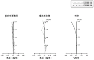
Fig. 5 is an aberration diagram in the case where the projection distance of the projection optical system 3A is a reference distance. Fig. 6 is an aberration diagram in the case where the projection distance of the projection optical system 3A is a long distance. Fig. 7 is an aberration diagram in the case where the projection distance of the projection optical system 3A is a short distance. In each of the aberration diagrams of fig. 5 to 7, the right diagram is a distortion aberration diagram, the center diagram is an astigmatism diagram, and the left diagram is a spherical aberration diagram. As shown in the respective aberration diagrams of fig. 5 to 7, spherical aberration, astigmatism, and distortion aberration are corrected well in the projection optical system 3A.
In the projection optical system 3A of this example, no intermediate image is formed inside, allowing the generation of distortion aberration. Therefore, the projection optical system 3A can be downsized. On the other hand, the light modulation element 18 forms a projection image having distortion that corrects distortion aberration of the projection optical system 3A. Therefore, the projector 1 can project an enlarged image with distortion aberration suppressed.
(example 2)
Fig. 8 is a structural diagram of a projection optical system of embodiment 2. The projection optical system 3B of this example is composed of, in order from the enlargement side, a1 st lens group LG1 having negative refractive power, a 2 nd lens group LG2 having positive refractive power, an aperture stop O, and a 3 rd lens group LG3 having positive refractive power. The projection optical system 3B has 12 lenses as a whole. The projection optical system 3B has a cross dichroic prism 19 between the light modulation element 18 and the reduction-side first lens located closest to the reduction side. The reduction-side 1 st lens is a12 th lens L12. In the projection optical system 3B, when the projection distance is changed, the distance between the entire lens system and the cross dichroic prism 19 is changed to perform focusing.
The 1 st lens group LG1 has 3 negative lenses. The 3 negative lenses are all single lenses. In this example, the 1 st lens group LG1 is composed of 3 negative lenses and 1 positive lens. Specifically, the 1 st lens group LG1 is composed of a1 st lens L1 having a negative refractive power with a convex surface facing the magnification side, a 2 nd lens L2 having a negative refractive power with a convex surface facing the magnification side, a 3 rd lens L3 having a negative refractive power with a convex surface facing the magnification side, and a 4 th lens L4 having a positive refractive power with a convex surface facing the magnification side. The 1 st lens L1 is a glass lens. The 1 st lens L1, the 2 nd lens L2, the 3 rd lens L3, and the 4 th lens L4 each have a concave-convex shape. Further, 1 lens of the lenses of the 1 st lens group LG1 has an aspherical surface on the magnification-side surface. In this example, both surfaces of the 4 th lens L4 are aspherical.
The 2 nd lens group LG2 has 2 positive lenses. Specifically, the 2 nd lens group LG2 is composed of a 5 th lens L5, a 6 th lens L6, and a 7 th lens L7. The 5 th lens L5 and the 7 th lens are positive lenses. Further, the 5 th lens L5 and the 6 th lens L6 constitute a1 st cemented lens SL 1. The 5 th lens L5 has a convex shape on the enlargement side and the reduction side. The 6 th lens L6 has a concave-convex shape with a convex surface facing the reduction side, and has a negative refractive power. The 7 th lens L7 has a convex shape on the enlargement side and the reduction side.
The 3 rd lens group LG3 has a plurality of positive lenses. Further, at least 1 positive lens out of the plurality of positive lenses of the 3 rd lens group LG3 constitutes a cemented lens. In the 3 rd lens group LG3, the 12 th lens L12 located on the most reduced side is a positive lens with a convex surface facing the reduced side. In other words, the reduction-side 1 st lens is a positive lens with a convex surface facing the reduction side. That is, the 3 rd lens group LG3 is composed of 5 lenses of the 8 th lens L8, the 9 th lens L9, the 10 th lens L10, the 11 th lens L11 and the 12 th lens L12. The 8 th, 10 th, and 12 th lenses L8, L10, and L12 are positive lenses. The 3 lenses of the 9 th lens L9, the 10 th lens L10, and the 11 th lens L11 constitute a 2 nd cemented lens SL 2. More specifically, the 8 th lens L8 has a concave-convex shape with a convex surface facing the reduction side, and has a positive refractive power. The 8 th lens L8 has an aspherical surface on both surfaces. The 9 th lens L9 has a concave shape on the enlargement side and the reduction side, and has negative refractive power. The 10 th lens L10 has a convex shape on the enlargement side and the reduction side, and has a positive refractive power. The 11 th lens L11 has a concave-convex shape with a convex surface facing the reduction side, and has a negative refractive power. The 12 th lens L12 has a convex shape on the enlargement side and the reduction side.
Here, when the focal length of the entire system is F, the F value is FNo, and the half field angle is ω, the data of the projection optical system 3B is as follows.
f:5.8
FNo:2.00
ω:68.50
The lens data of the projection optical system 3B is as follows.

The variable interval 1 and the variable interval 2 when focusing is performed by changing the projection distance are as follows.

Next, aspheric data of the surface numbers 7 and 8 of the 4 th lens L4 and the surface numbers 15 and 16 of the 9 th lens L9 are as follows.

(projection image and magnified image)
Fig. 9 is an explanatory diagram of the projection image. The thick line of fig. 9 is a pattern of the projected image. Thin lines in fig. 9 indicate display regions of images on the light modulation element 18. Fig. 10 is an explanatory diagram of an enlarged image projected onto the screen S via the projection optical system 3B. The thick lines of fig. 10 are graphs of enlarged images in the case where the projected image of fig. 9 is projected onto the screen S. The thin lines in fig. 10 are graphics in the case where the display area of the image in the light modulation element 18 is projected onto the screen S. The one-dot chain line in fig. 10 is a figure in the case where the display area of the image in the light modulation element 18 is projected onto the screen S by the projection optical system having no distortion aberration.
In this example, when the projection image shown in fig. 9 is projected onto the screen S by the projection optical system 3B, as shown in fig. 10, the image also becomes a rectangular enlarged image without distortion. The image of the projected image is compressed at a position where the image height on the lower side of the display area of the image of the light modulation element 18 is highest. There is no field curvature in the projected image. Here, as shown by the one-dot chain line in fig. 10, the projection optical system 3B of the present example can obtain a large magnified image on the screen S even with the same focal length as compared with the projection optical system having no distortion aberration.
When the reduction-side numerical aperture is NA and the distortion aberration at the maximum image height on the reduction side is Dst, the projection optical system 3B of the present example satisfies the following conditional expression (1) and conditional expression (2).
0.2<NA…(1)
-45%<Dst<-10%…(2)
In this example, NA is 0.25, and conditional expression (1) is satisfied. Therefore, the projection optical system 3B can efficiently take in the light flux emitted from the light modulator 18. In this example, Dst is-34.8%, and conditional expression (2) is satisfied. Therefore, in this example, deterioration in the image quality of the enlarged image can be prevented or suppressed. In the projection optical system 3B, the lens diameter of the 1 st lens L1 can be reduced, and the number of lenses constituting the projection optical system 3B can be reduced.
Further, in this example, the 1 st lens group LG1 has 3 negative lenses. Therefore, the 1 st lens group LG1 can have distortion aberration in the range of conditional expression (2), and has a sufficient back focal length and a flat image plane.
The 1 st lens L1 and the 2 nd lens L2 have a concave-convex shape with a convex surface facing the enlargement side. Therefore, the projection optical system 3B has a wide angle of view such as ω 68.5, and can suppress generation of coma aberration and astigmatism in the peripheral portion.
Next, assuming that the focal length of the entire system is f, the focal length of the 1 st lens group LG1 is f1, and the combined focal length of the 2 nd lens group LG2 and the 3 rd lens group LG3 is f23, the projection optical system 3B of this example satisfies the following conditional expression (3) and conditional expression (4).
0.8<|f1/f|<2.2…(3)
0.2<|f1/f23|<0.6…(4)
In this example, f is 5.800 and f1 is-10.254. Therefore, | f1/f |, 1.77, satisfies conditional expression (3). In this example, f23 is 35.228. Therefore, | f1/f23|, 0.29, satisfies conditional expression (4). Therefore, the projection optical system 3B can correct coma aberration and field curvature while maintaining distortion aberration at a desired value. In addition, it has a large angle of view and can secure a back focus.
Further, when the focal length of the 2 nd lens group LG2 is set to f2, the projection optical system 3B satisfies the following conditional expression (5).
4.0<f2/f<10.0…(5)
In this example, f2 is 37.015. Therefore, f2/f is 6.38, and conditional expression (5) is satisfied. Therefore, the projection optical system 3B can correct coma aberration and astigmatism in a well-balanced manner.
When the average value of the refractive index of the positive lenses included in the 2 nd lens group LG2 is N and the average value of the abbe number is V, the projection optical system 3B satisfies the following conditional expression (6) and conditional expression (7).
N>1.65…(6)
v<35…(7)
In this example, N is 1.72, and conditional expression (6) is satisfied. Further, V is 31.51, and satisfies conditional expression (7). Therefore, the projection optical system 3B can suppress chromatic aberration of magnification.
In this example, the 12 th lens L12 positioned on the most reduced side in the 3 rd lens group LG3 is a positive lens with the convex surface facing the reduced side. When the focal length of the 3 rd lens group LG3 is f3, the projection optical system 3B of this example satisfies the following conditional expression (8).
2.0<f3/f<6.0…(8)
In this example, f3 is 27.256. Therefore, f3/f is 4.70, and conditional expression (8) is satisfied. Therefore, the projection optical system 3B easily secures the back focal length and secures the reduction-side numerical aperture for taking in the light beam from the light modulation element 18.
Here, in this example, the 1 st lens L1 of the 1 st lens group LG1 is a glass lens having spherical surfaces on the enlargement side and the reduction side. In this example, since the hardness of the 1 st lens L1 is high, it is possible to suppress the 1 st lens L1 from being damaged when dirt or the like is wiped off.
Fig. 11 is an aberration diagram in the case where the projection distance of the projection optical system 3B is the reference distance. Fig. 12 is an aberration diagram in the case where the projection distance of the projection optical system 3B is a long distance. Fig. 13 is an aberration diagram in the case where the projection distance of the projection optical system 3B is a short distance. In each of the aberration diagrams of fig. 11 to 13, the right diagram is a distortion aberration diagram, the center diagram is an astigmatism diagram, and the left diagram is a spherical aberration diagram. As shown in the respective aberration diagrams of fig. 11 to 13, spherical aberration, astigmatism, and distortion aberration are corrected well in the projection optical system 3B.
In the projection optical system 3B of this example, no intermediate image is formed inside, allowing the generation of distortion aberration. Therefore, the projection optical system 3B can be downsized. On the other hand, the light modulation element 18 forms a projection image having distortion that corrects distortion aberration of the projection optical system 3B. Therefore, the projector 1 can project an enlarged image with distortion aberration suppressed.
(example 3)
Fig. 14 is a structural diagram of a projection optical system of embodiment 3. The projection optical system 3C of this example is composed of, in order from the enlargement side, a1 st lens group LG1 having negative refractive power, a 2 nd lens group LG2 having positive refractive power, an aperture stop O, and a 3 rd lens group LG3 having positive refractive power. The projection optical system 3C has 11 lenses as a whole. The projection optical system 3C has a cross dichroic prism 19 between the light modulation element 18 and the reduction-side first lens located closest to the reduction side. The reduction-side 1 st lens is an 11 th lens L11. In the projection optical system 3C, when the projection distance is changed, the distance between the entire lens system and the cross dichroic prism 19 is changed to perform focusing.
The 1 st lens group LG1 is composed of 4 negative lenses. The 4 negative lenses are all single lenses. Specifically, the 1 st lens group LG1 is composed of a1 st lens L1 having a negative refractive power with a convex surface toward the magnification side, a 2 nd lens L2 having a negative refractive power with a convex surface toward the magnification side, a 3 rd lens L3 having a negative refractive power with a convex surface toward the magnification side, and a 4 th lens L4 having a concave shape on the magnification side and the reduction side in the vicinity of the optical axis. The 1 st lens L1, the 2 nd lens L2, the 3 rd lens L3, and the 4 th lens L4 each have a concave-convex shape. The 1 st lens L1 is a plastic lens. Further, 1 lens of the lenses of the 1 st lens group LG1 has an aspherical surface on the magnification-side surface. In this example, both surfaces of the 1 st lens L1 are aspherical. Further, both surfaces of the 4 th lens L4 are aspherical.
The 2 nd lens group LG2 has 2 positive lenses. Specifically, the 2 nd lens group LG2 is composed of a 5 th lens L5, a 6 th lens L6, and a 7 th lens L7. The 5 th lens L5 and the 7 th lens are positive lenses. The 5 th lens L5, the 6 th lens L6, and the 7 th lens L7 are the 1 st cemented lens SL1 cemented to each other. The 5 th lens L5 has a convex shape on the enlargement side and the reduction side. The 6 th lens L6 has a concave shape on the enlargement side and the reduction side, and has negative refractive power. The 7 th lens L7 has a convex shape on the enlargement side and the reduction side.
The 3 rd lens group LG3 has a plurality of positive lenses. Further, at least 1 positive lens out of the plurality of positive lenses of the 3 rd lens group LG3 constitutes a cemented lens. In the 3 rd lens group LG3, the 11 th lens positioned on the most reduced side is a positive lens with a convex surface facing the reduced side. In other words, the reduction-side 1 st lens is a positive lens with a convex surface facing the reduction side. Specifically, the 3 rd lens group LG3 is composed of 4 lenses of the 8 th lens L8, the 9 th lens L9, the 10 th lens L10, and the 11 th lens L11. The 8 th lens L8, the 10 th lens L10, and the 11 th lens L11 are positive lenses. The 9 th lens L9 and the 10 th lens L10 constitute a 2 nd cemented lens SL 2. More specifically, the 8 th lens L8 has a concave-convex shape with a convex surface facing the reduction side, and has a positive refractive power. The 8 th lens L8 has an aspherical surface on both surfaces. The 9 th lens L9 has a concave shape on the enlargement side and the reduction side, and has negative refractive power. The 10 th lens L10 has a convex shape on the enlargement side and the reduction side. The 11 th lens L11 has a convex shape on the enlargement side and the reduction side.
Here, when the focal length of the entire system is F, the F value is FNo, and the half field angle is ω, the data of the projection optical system 3C is as follows.
f:4.8
FNo:2.00
ω:69.19
The lens data of the projection optical system 3C is as follows.

The variable interval 1 and the variable interval 2 when focusing is performed by changing the projection distance are as follows.

Next, aspheric data of the surface numbers 1 and 2 of the 1 st lens L1, the surface numbers 7 and 8 of the 4 th lens L4, and the surface numbers 14 and 15 of the 8 th lens L8 are as follows.

(projection image and magnified image)
Fig. 15 is an explanatory diagram of the projection image. The thick line of fig. 15 is a pattern of the projected image. Thin lines in fig. 15 indicate display regions of images on the light modulation element 18. Fig. 16 is an explanatory diagram of an enlarged image projected onto the screen S via the projection optical system 3C. The thick lines in fig. 16 are the graphics of the enlarged image in the case where the projected image of fig. 15 is projected onto the screen S. The thin lines in fig. 16 are graphics in the case where the display area of the image in the light modulation element 18 is projected on the screen S. The one-dot chain line in fig. 16 is a figure in the case where the display area of the image in the light modulation element 18 is projected onto the screen S by the projection optical system having no distortion aberration.
In this example, when the projection image shown in fig. 15 is projected onto the screen S by the projection optical system 3C, the image is a rectangular enlarged image without distortion as shown in fig. 16. The image of the projected image is compressed at a position where the image height on the lower side of the display area of the image of the light modulation element 18 is highest. There is no field curvature in the projected image. Here, as shown by the one-dot chain line in fig. 16, the projection optical system 3C of the present example can obtain a large magnified image on the screen S even with the same focal length as compared with a projection optical system having no distortion aberration.
In fig. 16, the reason why the missing of the corners on both sides of the upper end of the image in the case of projecting the display region of the image on the light modulator 18 onto the screen S is that the height of the image on the corners on both sides of the upper end of the display region of the image on the light modulator 18 exceeds the image circle of the projection optical system 3C, and light does not pass through. However, the image of the projected image displayed on the display area of the image in the light modulation element 18 is compressed at the position where the image height on the lower side of the display area of the image in the light modulation element 18 is highest. Therefore, the projected image is not missing.
When the reduction-side numerical aperture is NA and the distortion aberration at the maximum image height on the reduction side is Dst, the projection optical system 3C of the present example satisfies the following conditional expression (1) and conditional expression (2).
0.2<NA…(1)
-45%<Dst<-10%…(2)
In this example, NA is 0.25, and conditional expression (1) is satisfied. Therefore, the projection optical system 3C can efficiently take in the light flux emitted from the light modulator 18. In this example, Dst is-25.0%, and conditional expression (2) is satisfied. Therefore, in this example, deterioration in the image quality of the enlarged image can be prevented or suppressed. In the projection optical system 3C, the lens diameter of the 1 st lens L1 can be reduced, and the number of lenses constituting the projection optical system 3C can be reduced.
Further, in this example, the 1 st lens group LG1 has 3 negative lenses. Therefore, the 1 st lens group LG1 can have distortion aberration in the range of conditional expression (2), and has a sufficient back focal length and a flat image plane.
The 1 st lens L1 and the 2 nd lens L2 have a concave-convex shape with a convex surface facing the enlargement side. Therefore, the projection optical system 3C has a wide angle of view such as ω 69.19, and can suppress generation of coma aberration and astigmatism in the peripheral portion.
Next, assuming that the focal length of the entire system is f, the focal length of the 1 st lens group LG1 is f1, and the combined focal length of the 2 nd lens group LG2 and the 3 rd lens group LG3 is f23, the projection optical system 3C of this example satisfies the following conditional expression (3) and conditional expression (4).
0.8<|f1/f|<2.2…(3)
0.2<|f1/f23|<0.6…(4)
In this example, f is 4.800 and f1 is-6.350. Therefore, | f1/f |, 1.32, satisfies conditional expression (3). In this example, f23 is 23.553. Therefore, | f1/f23|, 0.27, satisfies conditional expression (4). Therefore, the projection optical system 3C can correct coma aberration and field curvature while maintaining distortion aberration at a desired value. In addition, it has a large angle of view and can secure a back focus.
When the focal length of the 2 nd lens group LG2 is f2, the projection optical system 3C satisfies the following conditional expression (5).
4.0<f2/f<10.0…(5)
In this example, f2 is 24.154. Therefore, f2/f is 5.03, and conditional expression (5) is satisfied. Therefore, the projection optical system 3C can correct coma aberration and astigmatism in a well-balanced manner.
When the average value of the refractive index of the positive lenses included in the 2 nd lens group LG2 is N and the average value of the abbe number is V, the projection optical system 3C satisfies the following conditional expression (6) and conditional expression (7).
N>1.65…(6)
v<35…(7)
In this example, N is 1.71, and conditional expression (6) is satisfied. Further, V is 29.77, and conditional expression (7) is satisfied. Therefore, the projection optical system 3C can suppress chromatic aberration of magnification.
In this example, the 13 th lens L13 positioned on the most reduced side in the 3 rd lens group LG3 is a positive lens with the convex surface facing the reduced side. When the focal length of the 3 rd lens group LG3 is f3, the projection optical system 3C satisfies the following conditional expression (8).
2.0<f3/f<6.0…(8)
In this example, f3 is 18.952. Therefore, f3/f is 3.95, and conditional expression (8) is satisfied. Therefore, the projection optical system 3C easily secures the back focal length and secures the reduction-side numerical aperture for taking in the light beam from the light modulation element 18.
Here, the 1 st lens L1 of the 1 st lens group LG1 is a plastic lens having aspherical surfaces on both sides. In this example, since the 1 st lens L1 is a plastic lens, the 1 st lens L1 is likely to have an aspherical surface. Further, since the 1 st lens L1 has aspherical surfaces on both surfaces, it is easy to control the amount of distortion aberration in the projection optical system 3C.
Further, in this example, since the 1 st lens L1 has aspherical surfaces on both surfaces, the number of lenses of the projection optical system 3C can be reduced and the total lens length of the projection optical system 3C can be shortened as compared with the case where the 1 st lens L1 does not have an aspherical surface. Further, since the lens thickness of the 1 st lens L1 changes in the vicinity of the optical axis and in the peripheral portion, the thickness deviation ratio is large, and the lens diameter is also large. Therefore, when the 1 st lens L1 is a plastic lens, the cost of the 1 st lens L1 can be reduced as compared with the case where the 1 st lens L1 is a glass lens.
Fig. 17 is an aberration diagram in the case where the projection distance of the projection optical system 3C is the reference distance. Fig. 18 is an aberration diagram in the case where the projection distance of the projection optical system 3C is a long distance. Fig. 19 is an aberration diagram in the case where the projection distance of the projection optical system 3C is a short distance. In each of the aberration diagrams of fig. 17 to 19, the right diagram is a distortion aberration diagram, the center diagram is an astigmatism diagram, and the left diagram is a spherical aberration diagram. As shown in the respective aberration diagrams of fig. 17 to 19, spherical aberration, astigmatism, and distortion aberration are corrected well in the projection optical system 3C.
In the projection optical system 3C of this example, no intermediate image is formed inside, allowing the generation of distortion aberration. Therefore, the projection optical system 3C can be downsized. On the other hand, the light modulation element 18 forms a projection image having distortion that corrects distortion aberration of the projection optical system 3C. Therefore, the projector 1 can project an enlarged image with distortion aberration suppressed.
(example 4)
Fig. 20 is a structural view of a projection optical system of embodiment 4. The projection optical system 3D of this example is composed of, in order from the enlargement side, a1 st lens group LG1 having negative refractive power, a 2 nd lens group LG2 having positive refractive power, an aperture stop O, and a 3 rd lens group LG3 having positive refractive power. The projection optical system 3D has 10 lenses as a whole. The projection optical system 3D has a cross dichroic prism 19 between the light modulation element 18 and the reduction-side 1 st lens located on the most reduction side. The reduction-side 1 st lens is a 10 th lens L10. In the projection optical system 3D, when the projection distance is changed, the distance between the entire lens system and the cross dichroic prism 19 is changed to perform focusing.
The 1 st lens group LG1 has 3 negative lenses. The 3 negative lenses are all single lenses. In this example, the 1 st lens group LG1 is composed of 3 negative lenses. Specifically, the 1 st lens group LG1 is composed of a1 st lens L1 having a negative refractive power with a convex surface facing the magnification side, a 2 nd lens L2 having a negative refractive power with a convex surface facing the magnification side, and a 3 rd lens L3 having a negative refractive power with a convex surface facing the magnification side. The 1 st lens L1, the 2 nd lens L2, and the 3 rd lens L3 each have a concave-convex shape. The 1 st lens L1 is a plastic lens. Further, 1 lens of the lenses of the 1 st lens group LG1 has an aspherical surface on the magnification-side surface. In this example, both surfaces of the 1 st lens L1 are aspherical. Both surfaces of the 3 rd lens L3 are aspherical. Both surfaces of the 7 th lens L7 are aspherical.
The 2 nd lens group LG2 has 1 positive lens. Specifically, the 2 nd lens group LG2 is composed of a 4 th lens, a 5 th lens L5, and a 6 th lens L6. The 4 th lens L4 and the 6 th lens L6 are positive lenses. The 4 th lens L4, the 5 th lens L5, and the 6 th lens L6 are the 1 st cemented lens SL 1. The 4 th lens L4 has a convex shape on the enlargement side and the reduction side. The 5 th lens L5 has a concave shape on the enlargement side and the reduction side, and has a negative refractive power. The 6 th lens L6 has a convex shape on the enlargement side and the reduction side.
The 3 rd lens group LG3 has a plurality of positive lenses. Further, at least 1 positive lens out of the plurality of positive lenses of the 3 rd lens group LG3 constitutes a cemented lens. In the 3 rd lens group LG3, the 10 th lens L10 located on the most reduced side is a positive lens with its convex surface facing the reduced side. In other words, the reduction-side 1 st lens is a positive lens with a convex surface facing the reduction side. Specifically, the 3 rd lens group LG3 is composed of 4 lenses of the 7 th lens L7, the 8 th lens L8, the 9 th lens L9, and the 10 th lens L10. The 7 th lens L7, the 9 th lens L9, and the 10 th lens L10 are positive lenses. The 8 th lens L8 and the 9 th lens L9 constitute a 2 nd cemented lens SL 2. The 10 th lens L10 is a reduction-side 1 st lens and is a positive lens with a convex surface facing the reduction side. More specifically, the 7 th lens L7 has a concave-convex shape with a convex surface facing the reduction side. The 7 th lens L7 has aspherical surfaces on both surfaces. The 8 th lens L8 has a concave shape on the enlargement side and the reduction side, and has negative refractive power. The 9 th lens L9 has a convex shape on the enlargement side and the reduction side. The 10 th lens L10 has a convex shape on the enlargement side and the reduction side.
Here, when the focal length of the entire system is F, the F value is FNo, and the half field angle is ω, the data of the projection optical system 3D is as follows.
f:5.8
FNo:2.00
ω:62.45
The lens data of the projection optical system 3D is as follows.

The variable interval 1 and the variable interval 2 when focusing is performed by changing the projection distance are as follows.

Next, aspheric data of the surface numbers 1 and 2 of the 1 st lens L1, the surface numbers 5 and 6 of the 3 rd lens L3, and the surface numbers 12 and 13 of the 7 th lens L7 are as follows.

(projection image and magnified image)
Fig. 21 is an explanatory diagram of the projection image. The thick line of fig. 21 is a pattern of the projected image. Thin lines in fig. 21 indicate display regions of images on the light modulation element 18. Fig. 22 is an explanatory diagram of an enlarged image projected onto the screen S via the projection optical system 3D. The thick line of fig. 22 is a figure of an enlarged image in the case where the projected image of fig. 21 is projected onto the screen S. The thin lines in fig. 22 are graphics in the case where the display region of the image in the light modulation element 18 is projected onto the screen S. The one-dot chain line in fig. 22 is a figure in the case where the display area of the image in the light modulation element 18 is projected onto the screen S by the projection optical system having no distortion aberration.
In this example, when the projection image shown in fig. 21 is projected onto the screen S by the projection optical system 3D, as shown in fig. 22, the image also becomes a rectangular enlarged image without distortion. The image of the projected image is compressed at a position where the image height on the lower side of the display area of the image of the light modulation element 18 is highest. There is no field curvature in the projected image. Here, as shown by the one-dot chain line in fig. 22, the projection optical system 3D of the present example can obtain a large magnified image on the screen S even with the same focal length as compared with a projection optical system having no distortion aberration.
When the reduction-side numerical aperture is NA and the distortion aberration at the maximum image height on the reduction side is Dst, the projection optical system 3D of the present example satisfies the following conditional expression (1) and conditional expression (2).
0.2<NA…(1)
-45%<Dst<-10%…(2)
In this example, NA is 0.25, and conditional expression (1) is satisfied. Therefore, the projection optical system 3D can efficiently take in the light flux emitted from the light modulator 18. In this example, Dst is-14.5%, and conditional expression (2) is satisfied. Therefore, in this example, deterioration in the image quality of the enlarged image can be prevented or suppressed. In the projection optical system 3D, the lens diameter of the 1 st lens L1 can be reduced, and the number of lenses constituting the projection optical system 3D can be reduced.
Further, in this example, the 1 st lens group LG1 has 3 negative lenses. Therefore, the 1 st lens group LG1 can have distortion aberration in the range of conditional expression (2), and has a sufficient back focal length and a flat image plane.
The 1 st lens L1 and the 2 nd lens L2 have a concave-convex shape with a convex surface facing the enlargement side. Therefore, the projection optical system 3D has a wide angle of view such as ω 62.45, and can suppress the occurrence of coma aberration and astigmatism in the peripheral portion.
Next, assuming that the focal length of the entire system is f, the focal length of the 1 st lens group LG1 is f1, and the combined focal length of the 2 nd lens group LG2 and the 3 rd lens group LG3 is f23, the projection optical system 3D of this example satisfies the following conditional expression (3) and conditional expression (4).
0.8<|f1/f|<2.2…(3)
0.2<|f1/f23|<0.6…(4)
In this example, f is 5.800 and f1 is-9.792. Therefore, | f1/f |, 1.69, satisfies conditional expression (3). In this example, f23 is 20.179. Therefore, | f1/f23|, 0.49, satisfies conditional expression (4). Therefore, the projection optical system 3D can correct coma aberration and field curvature while maintaining distortion aberration at a desired value. In addition, it has a large angle of view and can secure a back focus.
When the focal length of the 2 nd lens group LG2 is f2, the projection optical system 3D satisfies the following conditional expression (5).
4.0<f2/f<10.0…(5)
In this example, f2 is 42.716. Therefore, f2/f is 7.36, and conditional expression (5) is satisfied. Therefore, the projection optical system 3D can correct coma aberration and astigmatism in a well-balanced manner.
When the average value of the refractive index of the positive lenses included in the 2 nd lens group LG2 is N and the average value of the abbe number is V, the projection optical system 3D satisfies the following conditional expression (6) and conditional expression (7).
N>1.65…(6)
v<35…(7)
In this example, N is 1.71, and conditional expression (6) is satisfied. Further, V is 29.83, and conditional expression (7) is satisfied. Therefore, the projection optical system 3D can suppress chromatic aberration of magnification.
In this example, the 10 th lens L10 positioned on the most reduced side in the 3 rd lens group LG3 is a positive lens with the convex surface facing the reduced side. When the focal length of the 3 rd lens group LG3 is f3, the projection optical system 3D satisfies the following conditional expression (8).
2.0<f3/f<6.0…(8)
In this example, f3 is 19.455. Therefore, f3/f is 3.35, and conditional expression (8) is satisfied. Therefore, the projection optical system 3D easily ensures the back focal length and ensures the reduction-side numerical aperture for taking in the light beam from the light modulation element 18.
Here, the 1 st lens L1 of the 1 st lens group LG1 is a plastic lens having aspherical surfaces on both sides. In this example, since the 1 st lens L1 is a plastic lens, the 1 st lens L1 is likely to have an aspherical surface. Further, since the 1 st lens L1 has aspherical surfaces on both surfaces, it is easy to control the amount of distortion aberration in the projection optical system 3D. Further, the number of lenses of the projection optical system 3D can be reduced, and the total lens length of the projection optical system 3D can be shortened. Further, the cost of the 1 st lens L1 can be reduced.
Fig. 23 is an aberration diagram in the case where the projection distance of the projection optical system 3D is the reference distance. Fig. 24 is an aberration diagram in the case where the projection distance of the projection optical system 3D is a long distance. Fig. 25 is an aberration diagram in the case where the projection distance of the projection optical system 3D is a short distance. In each of the aberration diagrams of fig. 23 to 25, the right diagram is a distortion aberration diagram, the center diagram is an astigmatism diagram, and the left diagram is a spherical aberration diagram. As shown in the respective aberration diagrams of fig. 23 to 25, spherical aberration, astigmatism, and distortion aberration are corrected well in the projection optical system 3D.
In the projection optical system 3D of this example, no intermediate image is formed inside, allowing the generation of distortion aberration. Therefore, the projection optical system can be miniaturized in 3D. On the other hand, the light modulation element 18 forms a projection image having distortion that corrects distortion aberration of the projection optical system 3D. Therefore, the projector 1 can project an enlarged image with distortion aberration suppressed.
(example 5)
Fig. 26 is a structural view of a projection optical system of embodiment 5. The projection optical system 3E of this example is composed of, in order from the enlargement side, a1 st lens group LG1 having negative refractive power, a 2 nd lens group LG2 having positive refractive power, an aperture stop O, and a 3 rd lens group LG3 having positive refractive power. The projection optical system 3E has 9 lenses as a whole. The projection optical system 3E has a cross dichroic prism 19 between the light modulation element 18 and the reduction-side first lens located closest to the reduction side. The reduction-side 1 st lens is a 9 th lens L9. In the projection optical system 3E, when the projection distance is changed, the distance between the 1 st lens group LG1 and the 2 nd lens group LG2 is changed to perform focusing.
The 1 st lens group LG1 has 3 negative lenses. The 3 negative lenses are all single lenses. In this example, the 1 st lens group LG1 is composed of 3 negative lenses. Specifically, the 1 st lens group LG1 is composed of a1 st lens L1 having a negative refractive power with a convex surface facing the magnification side, a 2 nd lens L2 having a negative refractive power with a convex surface facing the magnification side, and a 3 rd lens L3 having a negative refractive power with a convex surface facing the reduction side. The 1 st lens L1, the 2 nd lens L2, and the 3 rd lens L3 each have a concave-convex shape. The 1 st lens L1 is a plastic lens. Further, 1 lens of the lenses of the 1 st lens group LG1 has an aspherical surface on the magnification-side surface. In this example, both surfaces of the 1 st lens L1 are aspherical.
The 2 nd lens group LG2 has 1 positive lens. In this example, the 2 nd lens group LG2 is composed of the 4 th lens L4, and the 4 th lens L4 has a convex shape on the enlargement side and the reduction side and has a positive refractive power.
The 3 rd lens group LG3 has a plurality of positive lenses. Further, at least 1 positive lens out of the plurality of positive lenses of the 3 rd lens group LG3 constitutes a cemented lens. In the 3 rd lens group LG3, the 9 th lens L9 located on the most reduced side is a positive lens with its convex surface facing the reduced side. In other words, the reduction-side 1 st lens is a positive lens with a convex surface facing the reduction side. Specifically, the 3 rd lens group LG3 is composed of 5 lenses of the 5 th lens L5, the 6 th lens L6, the 7 th lens L7, the 8 th lens L8 and the 9 th lens L9. The 5 th lens L5, the 7 th lens L7, and the 9 th lens L9 are positive lenses. The 5 th lens L5 and the 6 th lens L6 constitute a1 st cemented lens SL 1. The 8 th lens L8 and the 9 th lens L9 constitute a 2 nd cemented lens SL 2. More specifically, the 5 th lens L5 has a concave-convex shape with a convex surface facing the reduction side. The 6 th lens L6 has a concave-convex shape with a convex surface facing the reduction side, and has a negative refractive power. The 7 th lens L7 has a convex shape on the enlargement side and the reduction side. The 7 th lens L7 has aspherical surfaces on both surfaces. The 8 th lens L8 has a concave-convex shape with a convex surface facing the enlargement side, and has a negative refractive power. The 9 th lens L9 has a convex shape on the enlargement side and the reduction side.
Here, when the focal length of the entire system is F, the F value is FNo, and the half field angle is ω, the data of the projection optical system 3E is as follows.
f:5.18
FNo:2.00
ω:67.70
The lens data of the projection optical system 3E is as follows.

The variable interval 1 and the variable interval 2 when focusing is performed by changing the projection distance are as follows.

Next, aspheric data of the surface numbers 1 and 2 of the 1 st lens L1 and the surface numbers 13 and 14 of the 7 th lens L7 are as follows.

(projection image and magnified image)
Fig. 27 is an explanatory diagram of the projection image. The thick line of fig. 27 is a pattern of the projected image. Thin lines in fig. 27 indicate display regions of images on the light modulation element 18. Fig. 28 is an explanatory diagram of an enlarged image projected onto the screen S via the projection optical system 3E. The thick line of fig. 28 is a figure of an enlarged image in the case where the projection image of fig. 27 is projected onto the screen S. The thin lines in fig. 28 are graphics in the case where the display region of the image in the light modulation element 18 is projected onto the screen S. The one-dot chain line in fig. 28 is a figure in the case where the display area of the image in the light modulation element 18 is projected onto the screen S by the projection optical system having no distortion aberration.
In this example, when the projection image shown in fig. 27 is projected onto the screen S by the projection optical system 3E, as shown in fig. 28, the image also becomes a rectangular enlarged image without distortion. The image of the projected image is compressed at a position where the image height on the lower side of the display area of the image of the light modulation element 18 is highest. There is no field curvature in the projected image. Here, as shown by the one-dot chain line in fig. 28, the projection optical system 3E of the present example can obtain a large magnified image on the screen S even with the same focal length as compared with the projection optical system having no distortion aberration.
When the reduction-side numerical aperture is NA and the distortion aberration at the maximum image height on the reduction side is Dst, the projection optical system 3E of the present example satisfies the following conditional expression (1) and conditional expression (2).
0.2<NA…(1)
-45%<Dst<-10%…(2)
In this example, NA is 0.25, and conditional expression (1) is satisfied. Therefore, the projection optical system 3E can efficiently take in the light flux emitted from the light modulator 18. In this example, Dst is-30.0%, and conditional expression (2) is satisfied. Therefore, in this example, deterioration in the image quality of the enlarged image can be prevented or suppressed. In the projection optical system 3E, the lens diameter of the 1 st lens L1 can be reduced, and the number of lenses constituting the projection optical system 3E can be reduced.
Further, in this example, the 1 st lens group LG1 has 3 negative lenses. Therefore, the 1 st lens group LG1 can have distortion aberration in the range of conditional expression (2), and has a sufficient back focal length and a flat image plane.
The 1 st lens L1 and the 2 nd lens L2 have a concave-convex shape with a convex surface facing the enlargement side. Therefore, the projection optical system 3E has a wide angle of view such as ω 67.70, and can suppress generation of coma aberration and astigmatism in the peripheral portion.
Next, assuming that the focal length of the entire system is f, the focal length of the 1 st lens group LG1 is f1, and the combined focal length of the 2 nd lens group LG2 and the 3 rd lens group LG3 is f23, the projection optical system 3E of this example satisfies the following conditional expression (3) and conditional expression (4).
0.8<|f1/f|<2.2…(3)
0.2<|f1/f23|<0.6…(4)
In this example, f is 5.182 and f1 is-9.949. Therefore, | f1/f |, 1.92, satisfies conditional expression (3). In this example, f23 is 35.919. Therefore, | f1/f23|, 0.28, satisfies conditional expression (4). Therefore, the projection optical system 3E can correct coma aberration and field curvature while maintaining distortion aberration at a desired value. In addition, it has a large angle of view and can secure a back focus.
When the focal length of the 2 nd lens group LG2 is f2, the projection optical system 3E satisfies the following conditional expression (5).
4.0<f2/f<10.0…(5)
In this example, f2 is 41.451. Therefore, f2/f is 8.00, and conditional expression (5) is satisfied. Therefore, the projection optical system 3E can correct coma aberration and astigmatism in a well-balanced manner.
When the average value of the refractive index of the positive lenses included in the 2 nd lens group LG2 is N and the average value of the abbe number is V, the projection optical system 3E satisfies the following conditional expression (6) and conditional expression (7).
N>1.65…(6)
v<35…(7)
In this example, N is 1.76, and conditional expression (6) is satisfied. Further, V is 26.52, and satisfies conditional expression (7). Therefore, the projection optical system 3E can suppress chromatic aberration of magnification.
In this example, the 9 th lens L9 positioned on the most reduced side in the 3 rd lens group LG3 is a positive lens with the convex surface facing the reduced side. When the focal length of the 3 rd lens group LG3 is f3, the projection optical system 3E satisfies the following conditional expression (8).
2.0<f3/f<6.0…(8)
In this example, f3 is 25.832. Therefore, f3/f is 4.99, and conditional expression (8) is satisfied. Therefore, the projection optical system 3E easily secures the back focal length and secures the reduction-side numerical aperture for taking in the light beam from the light modulation element 18.
Here, in the projection optical system 3E, the interval of the 1 st lens group LG1 from the 2 nd lens group LG2 and the interval of the 2 nd lens group LG2 from the 3 rd lens group LG3 can be set longer as compared with other embodiments. Therefore, the total lens length of the projection optical system 3E is longer than that of the other embodiments. However, by setting the intervals with the respective lens groups LG1, LG2, LG3 to be long, the refractive power of the respective lenses constituting the projection optical system 3E can be weakened. As a result, the 2 nd lens group LG2 can be 1 positive lens only. In addition, when the interval between the lens groups LG1, LG2, and LG3 is set long, it is easy to change the projection direction by disposing an optical path deflecting element such as a mirror between the lens groups LG1, LG2, and LG 3.
Fig. 29 is an aberration diagram in the case where the projection distance of the projection optical system 3E is the reference distance. Fig. 30 is an aberration diagram in the case where the projection distance of the projection optical system 3E is a long distance. Fig. 31 is an aberration diagram in the case where the projection distance of the projection optical system 3E is a short distance. In each of the aberration diagrams of fig. 29 to 31, the right diagram is a distortion aberration diagram, the center diagram is an astigmatism diagram, and the left diagram is a spherical aberration diagram. As shown in the aberration diagrams of fig. 29 to 31, the spherical aberration, astigmatism, and distortion aberration are corrected well in the projection optical system 3E.
In the projection optical system 3E of this example, no intermediate image is formed inside, allowing the generation of distortion aberration. Therefore, the projection optical system 3E can be downsized. On the other hand, the light modulation element 18 forms a projection image having distortion that corrects distortion aberration of the projection optical system 3E. Therefore, the projector 1 can project an enlarged image with distortion aberration suppressed.
Claims (6)
1. A projection optical system characterized by comprising, in order from an enlargement side:
a1 st lens group having negative refractive power, comprising at least 3 negative lenses;
a 2 nd lens group having a positive refractive power, including at least 1 positive lens; and
a 3 rd lens group having a positive refractive power, comprising a plurality of positive lenses,
said at least 3 negative lenses of said 1 st lens group are all single lenses,
the 3 rd lens group has a cemented lens including at least 1 positive lens of the plurality of positive lenses,
when the numerical aperture on the reduction side of the projection optical system is NA and the distortion aberration at the maximum image height on the reduction side of the projection optical system is Dst, the following conditional expressions (1) and (2) are satisfied:
0.2<NA ……(1)
-45%<Dst<-10%……(2)。
2. projection optical system according to claim 1,
the following conditional expression (3) and conditional expression (4) are satisfied, assuming that a focal length of the entire system is f, a focal length of the 1 st lens group is f1, and a combined focal length of the 2 nd lens group and the 3 rd lens group is f 23:
0.8<|f1/f|<2.2……(3)
0.2<|f1/f23|<0.6……(4)。
3. projection optical system according to claim 1 or 2,
when the focal length of the 2 nd lens group is f2, the average value of the refractive index of the positive lens included in the 2 nd lens group is N, and the average value of the abbe number is V, the following conditional expressions (5), (6), and (7) are satisfied:
4.0<f2/f<10.0 ……(5)
N>1.65 ……(6)
V<35 ……(7)。
4. projection optical system according to claim 1,
the 1 st lens on the most diminished side in the 3 rd lens group is a positive lens with a convex surface facing the diminished side,
when the focal length of the 3 rd lens group is f3, the following conditional expression (8) is satisfied:
2.0<f3/f<6.0 ……(8)。
5. projection optical system according to claim 1,
1 lens of the lenses of the 1 st lens group has an aspherical surface on the magnification side.
6. A projector, characterized in that it has:
the projection optical system according to any one of claims 1 to 5;
a light source; and
an optical modulator disposed on a reduction-side conjugate surface of the projection optical system, modulating light from the light source, and forming a projection image having distortion for correcting distortion aberration of the projection optical system,
the projector projects the magnified image corrected for the distortion image difference to a conjugate plane on the magnification side of the projection optical system.
Applications Claiming Priority (2)
| Application Number | Priority Date | Filing Date | Title |
|---|---|---|---|
| JP2019120998A JP2021006858A (en) | 2019-06-28 | 2019-06-28 | Projection optical system and projector |
| JP2019-120998 | 2019-06-28 |
Publications (2)
| Publication Number | Publication Date |
|---|---|
| CN112147832A CN112147832A (en) | 2020-12-29 |
| CN112147832B true CN112147832B (en) | 2022-04-12 |
Family
ID=73887984
Family Applications (1)
| Application Number | Title | Priority Date | Filing Date |
|---|---|---|---|
| CN202010595884.5A Active CN112147832B (en) | 2019-06-28 | 2020-06-28 | Projection optical system and projector |
Country Status (3)
| Country | Link |
|---|---|
| US (1) | US11550132B2 (en) |
| JP (1) | JP2021006858A (en) |
| CN (1) | CN112147832B (en) |
Families Citing this family (4)
| Publication number | Priority date | Publication date | Assignee | Title |
|---|---|---|---|---|
| JP2021006858A (en) | 2019-06-28 | 2021-01-21 | セイコーエプソン株式会社 | Projection optical system and projector |
| JP2021006859A (en) * | 2019-06-28 | 2021-01-21 | セイコーエプソン株式会社 | Projection optical system and projector |
| CN114859634A (en) * | 2021-02-04 | 2022-08-05 | 深圳铭栋光电科技有限公司 | Light path structure component of steering projection lens |
| JP2023140823A (en) * | 2022-03-23 | 2023-10-05 | キヤノン株式会社 | Optical system and imaging apparatus having the same |
Citations (11)
| Publication number | Priority date | Publication date | Assignee | Title |
|---|---|---|---|---|
| US5666228A (en) * | 1995-09-28 | 1997-09-09 | Fuji Photo Optical Co., Ltd. | Retrofocus type lens |
| CN102411189A (en) * | 2010-09-17 | 2012-04-11 | 株式会社尼康 | Optical system, optical apparatus equipped therewith, and method for manufacturing optical system |
| WO2013024692A1 (en) * | 2011-08-18 | 2013-02-21 | 株式会社オプトロジック | Imaging lens |
| CN103403604A (en) * | 2011-02-24 | 2013-11-20 | 富士胶片株式会社 | Projector zoom lens and projector display device |
| JP2015060201A (en) * | 2013-09-20 | 2015-03-30 | 日立マクセル株式会社 | Imaging lens system and imaging device |
| CN205229554U (en) * | 2014-11-25 | 2016-05-11 | 富士胶片株式会社 | Imaging lens and imaging device |
| CN105629443A (en) * | 2016-03-30 | 2016-06-01 | 浙江大华技术股份有限公司 | Lens system and camera lens |
| JP2016200743A (en) * | 2015-04-13 | 2016-12-01 | キヤノン株式会社 | Optical system and imaging apparatus including the same |
| JP2017134235A (en) * | 2016-01-28 | 2017-08-03 | 富士フイルム株式会社 | Image capturing lens and image capturing device |
| JP2018004717A (en) * | 2016-06-28 | 2018-01-11 | 富士フイルム株式会社 | Zoom lens and image capturing device |
| JP2018060078A (en) * | 2016-10-06 | 2018-04-12 | 富士フイルム株式会社 | Imaging lens and imaging apparatus |
Family Cites Families (28)
| Publication number | Priority date | Publication date | Assignee | Title |
|---|---|---|---|---|
| JP3115879B2 (en) * | 1990-02-20 | 2000-12-11 | シチズン時計株式会社 | Optical device |
| JP3752025B2 (en) | 1995-08-25 | 2006-03-08 | ペンタックス株式会社 | Large aperture ultra wide angle lens system |
| US5724195A (en) | 1995-08-25 | 1998-03-03 | Asahi Kogaku Kogyo Kabushiki Kaisha | Fast super wide-angle lens system |
| KR20030077853A (en) | 2002-03-27 | 2003-10-04 | 삼성에스디아이 주식회사 | Projection lens having a wide angle of view |
| US7009765B2 (en) | 2002-08-16 | 2006-03-07 | Infocus Corporation | Wide angle lens system having a distorted intermediate image |
| JP4340469B2 (en) | 2003-03-28 | 2009-10-07 | リコー光学株式会社 | Projection lens and projection-type image display device |
| JP4340468B2 (en) | 2003-05-02 | 2009-10-07 | リコー光学株式会社 | Projection lens and projection-type image display device |
| WO2005124419A1 (en) | 2004-06-17 | 2005-12-29 | Nikon Corporation | Projector lens and projector employing such projector lens |
| JP2006047948A (en) | 2004-06-29 | 2006-02-16 | Konica Minolta Opto Inc | Projection optical system and projecting apparatus provided with the same |
| JP4464212B2 (en) | 2004-06-30 | 2010-05-19 | Hoya株式会社 | Fisheye lens system |
| JP2006098942A (en) | 2004-09-30 | 2006-04-13 | Elmo Co Ltd | Fisheye lens and photographing apparatus with the same |
| JP5033936B2 (en) | 2005-08-30 | 2012-09-26 | ペンタックスリコーイメージング株式会社 | Fisheye lens system and fisheye zoom lens system |
| JP4951278B2 (en) | 2005-08-30 | 2012-06-13 | ペンタックスリコーイメージング株式会社 | Fisheye lens system and fisheye zoom lens system |
| TWI284747B (en) | 2006-05-18 | 2007-08-01 | Young Optics Inc | Fixed-focus lens |
| JP2009186790A (en) * | 2008-02-07 | 2009-08-20 | Fujinon Corp | Projection lens and projection display device with the same |
| JP2010266577A (en) | 2009-05-13 | 2010-11-25 | Canon Inc | Optical system and optical equipment having the same |
| JP5424745B2 (en) | 2009-07-02 | 2014-02-26 | キヤノン株式会社 | Optical system and optical apparatus having the same |
| JP5549462B2 (en) | 2009-08-04 | 2014-07-16 | コニカミノルタ株式会社 | OPTICAL SYSTEM, IMAGE PROJECTION DEVICE AND IMAGING DEVICE EQUIPPED |
| JP5590498B2 (en) * | 2009-09-07 | 2014-09-17 | 株式会社ニコン | Projection device |
| JP6021534B2 (en) | 2012-09-04 | 2016-11-09 | キヤノン株式会社 | Zoom lens and imaging apparatus having the same |
| JP6383214B2 (en) | 2014-08-05 | 2018-08-29 | オリンパス株式会社 | Imaging optical system and optical apparatus including the same |
| WO2016021221A1 (en) * | 2014-08-05 | 2016-02-11 | オリンパス株式会社 | Image-forming optical system and optical device provided with same |
| CN208060922U (en) | 2015-09-29 | 2018-11-06 | 富士胶片株式会社 | Projection lens and projecting apparatus |
| KR102600453B1 (en) * | 2016-02-19 | 2023-11-10 | 삼성전자주식회사 | Optical lens assembly and electronic apparatus having the same |
| JP2017161569A (en) * | 2016-03-07 | 2017-09-14 | 富士フイルム株式会社 | Imaging lens and imaging apparatus |
| CN107450166A (en) | 2016-06-01 | 2017-12-08 | 精工爱普生株式会社 | Projection optics system and projection type video display device |
| JP6798270B2 (en) | 2016-11-21 | 2020-12-09 | セイコーエプソン株式会社 | Imaging lens system, imaging device and projector |
| JP2021006858A (en) | 2019-06-28 | 2021-01-21 | セイコーエプソン株式会社 | Projection optical system and projector |
-
2019
- 2019-06-28 JP JP2019120998A patent/JP2021006858A/en not_active Withdrawn
-
2020
- 2020-06-26 US US16/912,907 patent/US11550132B2/en active Active
- 2020-06-28 CN CN202010595884.5A patent/CN112147832B/en active Active
Patent Citations (11)
| Publication number | Priority date | Publication date | Assignee | Title |
|---|---|---|---|---|
| US5666228A (en) * | 1995-09-28 | 1997-09-09 | Fuji Photo Optical Co., Ltd. | Retrofocus type lens |
| CN102411189A (en) * | 2010-09-17 | 2012-04-11 | 株式会社尼康 | Optical system, optical apparatus equipped therewith, and method for manufacturing optical system |
| CN103403604A (en) * | 2011-02-24 | 2013-11-20 | 富士胶片株式会社 | Projector zoom lens and projector display device |
| WO2013024692A1 (en) * | 2011-08-18 | 2013-02-21 | 株式会社オプトロジック | Imaging lens |
| JP2015060201A (en) * | 2013-09-20 | 2015-03-30 | 日立マクセル株式会社 | Imaging lens system and imaging device |
| CN205229554U (en) * | 2014-11-25 | 2016-05-11 | 富士胶片株式会社 | Imaging lens and imaging device |
| JP2016200743A (en) * | 2015-04-13 | 2016-12-01 | キヤノン株式会社 | Optical system and imaging apparatus including the same |
| JP2017134235A (en) * | 2016-01-28 | 2017-08-03 | 富士フイルム株式会社 | Image capturing lens and image capturing device |
| CN105629443A (en) * | 2016-03-30 | 2016-06-01 | 浙江大华技术股份有限公司 | Lens system and camera lens |
| JP2018004717A (en) * | 2016-06-28 | 2018-01-11 | 富士フイルム株式会社 | Zoom lens and image capturing device |
| JP2018060078A (en) * | 2016-10-06 | 2018-04-12 | 富士フイルム株式会社 | Imaging lens and imaging apparatus |
Also Published As
| Publication number | Publication date |
|---|---|
| JP2021006858A (en) | 2021-01-21 |
| US11550132B2 (en) | 2023-01-10 |
| US20200409126A1 (en) | 2020-12-31 |
| CN112147832A (en) | 2020-12-29 |
Similar Documents
| Publication | Publication Date | Title |
|---|---|---|
| CN112147832B (en) | Projection optical system and projector | |
| US10620413B2 (en) | Projection optical system and projection type display device | |
| CN108227118B (en) | Projection optical system and projection type image display apparatus | |
| US10473902B2 (en) | Projection system and projection-type image display apparatus | |
| US6989946B2 (en) | Projection lens | |
| US8508855B2 (en) | Projection lens and projection-type display apparatus using the lens | |
| US10451962B2 (en) | Projection optical system and projection display device | |
| JP2007034082A (en) | Projection lens and projection type display device using same | |
| JP2008145770A (en) | Projection lens and projection type display apparatus using the same | |
| JP2018066879A (en) | Zoom lens for projection and projection type image display device | |
| JP2018036390A (en) | Wide angle lens, projection type display device, and imaging device | |
| CN110927941B (en) | Projection optical system and projection type image display device | |
| US20210063710A1 (en) | Imaging optical system, projection type display device, and imaging apparatus | |
| CN112147833B (en) | Projection optical system and projector | |
| JP2007079108A (en) | Two-group zoom projection lens and projection type display device | |
| US11415784B2 (en) | Imagaing optical system, projection display device, and imaging apparatus | |
| JP6745775B2 (en) | Imaging optical system, projection display device, and imaging device | |
| JP6735716B2 (en) | Imaging optical system, projection display device, and imaging device | |
| JP2006003655A (en) | Projection lens and projector using same | |
| CN114675397B (en) | Projection optical system and projector | |
| JP6982016B2 (en) | Imaging optical system, projection display device, and imaging device | |
| US20230314763A1 (en) | Projection system and projector | |
| JP2023022443A (en) | Optical system and projector | |
| CN116466535A (en) | Projection optical system and projector | |
| CN116893555A (en) | Projection optical system and projector |
Legal Events
| Date | Code | Title | Description |
|---|---|---|---|
| PB01 | Publication | ||
| PB01 | Publication | ||
| SE01 | Entry into force of request for substantive examination | ||
| SE01 | Entry into force of request for substantive examination | ||
| GR01 | Patent grant | ||
| GR01 | Patent grant |