CN112139949A - Metal part machining equipment capable of automatically replacing grinding head - Google Patents
Metal part machining equipment capable of automatically replacing grinding head Download PDFInfo
- Publication number
- CN112139949A CN112139949A CN202011097189.2A CN202011097189A CN112139949A CN 112139949 A CN112139949 A CN 112139949A CN 202011097189 A CN202011097189 A CN 202011097189A CN 112139949 A CN112139949 A CN 112139949A
- Authority
- CN
- China
- Prior art keywords
- cavity
- grinding
- chamber
- moving
- bevel gear
- Prior art date
- Legal status (The legal status is an assumption and is not a legal conclusion. Google has not performed a legal analysis and makes no representation as to the accuracy of the status listed.)
- Withdrawn
Links
Images


Classifications
-
- B—PERFORMING OPERATIONS; TRANSPORTING
- B24—GRINDING; POLISHING
- B24B—MACHINES, DEVICES, OR PROCESSES FOR GRINDING OR POLISHING; DRESSING OR CONDITIONING OF ABRADING SURFACES; FEEDING OF GRINDING, POLISHING, OR LAPPING AGENTS
- B24B27/00—Other grinding machines or devices
-
- B—PERFORMING OPERATIONS; TRANSPORTING
- B24—GRINDING; POLISHING
- B24B—MACHINES, DEVICES, OR PROCESSES FOR GRINDING OR POLISHING; DRESSING OR CONDITIONING OF ABRADING SURFACES; FEEDING OF GRINDING, POLISHING, OR LAPPING AGENTS
- B24B27/00—Other grinding machines or devices
- B24B27/0092—Grinding attachments for lathes or the like
-
- B—PERFORMING OPERATIONS; TRANSPORTING
- B24—GRINDING; POLISHING
- B24B—MACHINES, DEVICES, OR PROCESSES FOR GRINDING OR POLISHING; DRESSING OR CONDITIONING OF ABRADING SURFACES; FEEDING OF GRINDING, POLISHING, OR LAPPING AGENTS
- B24B41/00—Component parts such as frames, beds, carriages, headstocks
- B24B41/002—Grinding heads
-
- B—PERFORMING OPERATIONS; TRANSPORTING
- B24—GRINDING; POLISHING
- B24B—MACHINES, DEVICES, OR PROCESSES FOR GRINDING OR POLISHING; DRESSING OR CONDITIONING OF ABRADING SURFACES; FEEDING OF GRINDING, POLISHING, OR LAPPING AGENTS
- B24B41/00—Component parts such as frames, beds, carriages, headstocks
- B24B41/06—Work supports, e.g. adjustable steadies
Abstract
The invention discloses a metal part processing device capable of automatically replacing a grinding head, which comprises a grinding machine, wherein a grinding cavity with a forward opening is arranged in the grinding machine, a grinding device is arranged at the right side in the grinding cavity and comprises a grinding slide block cavity communicated with the right side of the grinding cavity, the processing part is fixed through a clamping device in a mode of fixing the part to be processed and then grinding, the part is preliminarily ground through a rough processing grinding head, then the finish processing grinding head is actively replaced through a conversion device for finish processing, the grinding head replacement through manpower is avoided, time and labor are saved, convenience and rapidness are realized, when the part needs to be processed in a large batch, a large amount of time is consumed for replacing the grinding head, the efficiency is low, the device can also adjust and grind the part, and the part can be fully processed at each angle, the effect is good without manual adjustment.
Description
Technical Field
The invention relates to the technical field of metal grinding, in particular to metal part processing equipment capable of automatically replacing a grinding head.
Background
In the technical field of metal grinding, metal parts usually need to be ground, different grinding heads need to be replaced for processing when the parts are ground, a common processing device needs to manually replace the grinding heads, time and labor are wasted, the grinding head replacement for processing is poor in processing effect when large-batch parts are ground, the common processing device cannot carry out all-dimensional automatic grinding on the parts, the angle needs to be manually adjusted, and the efficiency is low.
Disclosure of Invention
In order to solve the problems, the embodiment designs a metal part processing device capable of automatically replacing a grinding head, the metal part processing device capable of automatically replacing the grinding head comprises a grinding machine, a grinding cavity with a forward opening is arranged in the grinding machine, a grinding device is arranged on the right side in the grinding cavity, the grinding device comprises a grinding slide block cavity communicated with the right side of the grinding cavity, a grinding slide block capable of moving back and forth is arranged in the grinding slide block cavity, the grinding head is rotatably arranged on the left side of the grinding slide block, a grinding rotating shaft is rotatably arranged in the grinding head, a grinding tool fixing cavity is arranged in the grinding rotating shaft, a grinding tool cavity electromagnet is fixedly arranged on the right side in the grinding tool fixing cavity, a grinding tool fixing block capable of moving left and right is arranged on the left side in the grinding tool fixing cavity, a grinding tool cavity spring is fixedly connected between the grinding, a grinding tool connecting cavity is arranged in the grinding tool fixing block, a rough machining grinding tool is fixedly arranged in the grinding tool connecting cavity and can be used for rough machining grinding of parts, a replacement spring cavity is communicated with the rear side of the grinding cavity, a replacement cavity electromagnet is fixedly arranged at the lower side in the replacement spring cavity, a replacement box capable of moving up and down is arranged at the upper side of the replacement spring cavity, a replacement cavity spring is fixedly connected between the replacement box and the replacement cavity electromagnet, a rough machining grinding tool placing cavity communicated with the grinding cavity is arranged in the replacement box and can be used for storing the rough machining grinding tool, a finish machining grinding tool placing cavity communicated with the grinding cavity is arranged at the upper side of the rough machining grinding tool placing cavity, a finish machining grinding tool capable of moving back and forth is arranged in the finish machining grinding tool placing cavity, and the finish machining grinding tool can be used for finish machining grinding of the parts, grinding chamber left side is equipped with clamping device, clamping device locates including the intercommunication the left lift chamber in grinding chamber, the lift intracavity is equipped with the elevator that can reciprocate, be equipped with in the elevator with the tight chamber of clamp of grinding chamber intercommunication, press from both sides tight intracavity longitudinal symmetry and fixed clamp chamber electro-magnet that is equipped with, press from both sides tight intracavity longitudinal symmetry and be equipped with the pinch-off blades that can reciprocate, from top to bottom the pinch-off blades respectively with the tight chamber spring of clamp fixedly connected with clamp between the chamber electro-magnet, the pinch-off blades can press from both sides the part that needs the grinding and press from both sides tightly, grinding chamber downside intercommunication is equipped with the clearance chamber, clearance intracavity rear side is equipped with cleaning device, cleaning device can carry out iron fillings clearance.
The cleaning device comprises a fan blade rotating shaft cavity arranged at the rear side of the cleaning cavity, a fan blade rotating shaft bevel gear is arranged in the fan blade rotating shaft cavity, a fan blade rotating shaft is arranged in the fan blade rotating shaft cavity in a fixed mode, a fan blade rotating shaft is arranged in the axis of the fan blade rotating shaft bevel gear in a fixed mode, the outer circular surface of the front end of the fan blade rotating shaft extends to the fan blade fixedly arranged in the cleaning cavity, a collecting cavity is arranged in the cleaning cavity in a communicated mode, the fan blade can enable scrap iron in the cleaning cavity to enter the collecting cavity and be collected, and the front wall of the fan blade rotating shaft cavity is fixedly provided with a power motor right.
Preferably, the downside rotates and is equipped with transmission shaft bevel gear in the flabellum pivot intracavity, transmission shaft bevel gear axle center rigidity is equipped with the transmission shaft, flabellum pivot chamber downside is equipped with the synchronous belt chamber, the outer disc of transmission shaft lower extreme extends to the synchronous belt intracavity is fixed and is equipped with and rotates synchronous pulley, synchronous belt chamber right side is rotated and is equipped with transmission synchronous pulley, synchronous belt chamber right side is rotated and is equipped with driven synchronous pulley, driven synchronous pulley with transmission synchronous pulley and it has the hold-in range to rotate between the synchronous pulley jointly.
Preferably, a rotating shaft is fixedly arranged at the axis position of the transmission synchronous pulley, a rotating cavity is communicated with the rear side of the grinding sliding block cavity, the outer circular surface of the upper end of the rotating shaft extends to the rotating cavity and is rotatably provided with a rotating sleeve, a rotating sleeve bevel gear fixed on the outer circular surface of the rotating sleeve is arranged in the rotating cavity, a rotating spring cavity is communicated with the right side of the rotating cavity and is fixedly provided with a rotating cavity electromagnet, a rotating cavity moving block capable of moving up and down is arranged on the lower side of the rotating spring cavity, a rotating cavity spring is fixedly connected between the rotating cavity moving block and the rotating cavity electromagnet, and the left end of the rotating cavity moving block extends to the rotating cavity and is rotatably connected with the rotating sleeve.
Preferably, the left side of the rotating cavity is rotatably provided with a driven bevel gear, the axis of the driven bevel gear is fixedly provided with a driven shaft, the left side of the grinding slider is provided with a driven cavity, the outer circular surface of the left side of the driven shaft extends to the driven cavity, a first transmission bevel gear is fixedly arranged in the driven cavity, the grinding slider and the grinding head are rotatably connected with a bearing shaft, the driven cavity is internally provided with a bearing shaft bevel gear fixed on the outer circular surface of the bearing shaft, the bearing shaft bevel gear is meshed with the first transmission bevel gear, and the grinding head is internally fixedly provided with a transmission motor right facing the axis of the grinding rotating shaft and is in power connection with the transmission.
Preferably, a sliding connecting rod is fixedly arranged on the right end face of the grinding sliding block, a sliding sleeve is arranged on the right end of the sliding connecting rod in a rotating mode, a sliding sleeve shaft is fixedly arranged on the axis position of the sliding sleeve, a sliding sleeve bevel gear fixed to the outer circular face of the sliding sleeve is arranged in the rotating cavity, a second transmission bevel gear is fixedly arranged on the front end face of the sliding sleeve shaft, the sliding sleeve bevel gear is meshed with the driven bevel gear, and the second transmission bevel gear can be meshed with the rotating sleeve bevel gear.
Preferably, a movable sleeve cavity is arranged on the upper side of the rotating cavity, the outer circular surface of the upper end of the rotating shaft extends into the movable sleeve cavity to be rotatably provided with a movable sleeve, a movable sleeve bevel gear fixed on the outer circular surface of the movable sleeve is arranged in the movable sleeve cavity, a movable spring cavity is communicated with the right side in the movable sleeve cavity, a movable cavity electromagnet is fixedly arranged on the upper side in the movable spring cavity, a movable cavity slider capable of moving up and down is arranged on the lower side in the movable spring cavity, a movable cavity spring is fixedly connected between the movable cavity slider and the movable cavity electromagnet, the left end of the movable cavity slider extends into the movable sleeve cavity to be rotatably connected with the outer circular surface of the movable sleeve, a third transmission bevel gear is rotatably arranged on the left side in the movable sleeve cavity, a straight gear shaft is fixedly arranged on the axis of the third transmission bevel gear, the outer disc of straight-tooth gear axle left end extends to the straight-tooth gear intracavity is fixed and is equipped with the straight-tooth gear, straight-tooth gear chamber downside is equipped with the rack plate that can the back-and-forth movement, the fixed rack and pinion that is equipped with of rack plate up end, rack and pinion with the straight-tooth gear meshing, the fixed supporting shoe that is equipped with of terminal surface under the rack plate, the supporting shoe lower extreme extends to in the grinding chamber with the outer disc fixed connection of grinding slider.
Preferably, a synchronous belt shaft is fixedly arranged on the axis of the driven synchronous belt pulley, the outer circular surface of the upper end of the synchronous belt shaft extends to the lifting cavity and is rotatably provided with a bearing sleeve, the left side of the lifting cavity is communicated with a bearing spring cavity, the upper side of the bearing spring cavity is fixedly provided with a bearing cavity electromagnet, the lower side of the bearing spring cavity is provided with a bearing cavity moving block capable of moving up and down, the right end of the bearing cavity moving block is rotatably connected with the outer circular surface of the bearing sleeve, a bearing cavity spring is fixedly connected between the bearing cavity moving block and the bearing cavity electromagnet, the upper wall of the lifting cavity is rotatably provided with a lead screw, the outer circular surface of the lead screw is in threaded connection with the lifting block, and the bearing sleeve.
Preferably, the lift chamber upside is equipped with the grinding fluid chamber, grinding fluid chamber left side be equipped with the spray line of grinding chamber intercommunication, the spray line with fixed water pump and the intercommunication of being equipped with between the grinding fluid chamber, clearance chamber right side intercommunication is equipped with the door plant chamber, door plant intracavity hinged joint has the door plant that can overturn right.
The invention has the beneficial effects that: according to the invention, by fixing the part to be machined firstly and then grinding the part, the machined part is fixed through the clamping device firstly, then the rough machining grinding head is used for primarily grinding the part, and then the finish machining grinding head is actively replaced through the conversion device for finish machining, so that the grinding head is prevented from being replaced manually, time and labor are saved, convenience and rapidness are realized, when the part is machined in a large batch, a large amount of time is consumed for replacing the grinding head, the efficiency is low, in addition, the angle adjusting grinding can be carried out on the part, the part can be fully machined at each angle, the manual adjustment is not needed, and the effect is good.
Drawings
In order to more clearly illustrate the embodiments of the invention or the technical solutions in the prior art, the drawings used in the description of the embodiments or the prior art will be briefly described below, and it is obvious that the drawings in the following description are only some embodiments of the invention, and it is obvious for those skilled in the art that other drawings can be obtained based on these drawings without creative efforts.
The invention is further illustrated with reference to the following figures and examples.
Fig. 1 is a schematic view of the overall structure of a metal part machining apparatus capable of automatically replacing a grinding head according to the present invention.
FIG. 2 is a schematic view of the structure A-A of FIG. 1;
FIG. 3 is a schematic diagram of B-B of FIG. 1;
FIG. 4 is an enlarged schematic view of C in FIG. 1;
fig. 5 is an enlarged schematic view of D in fig. 1.
Detailed Description
The invention will now be described in detail with reference to fig. 1-5, wherein for ease of description the orientations described hereinafter are now defined as follows: the up, down, left, right, and front-back directions described below correspond to the up, down, left, right, and front-back directions in the projection relationship of fig. 1 itself.
The invention relates to metal part processing equipment capable of automatically replacing grinding heads, which comprises a grinding machine 11, wherein a grinding cavity 48 with a forward opening is arranged in the grinding machine 11, a grinding device 101 is arranged at the right side in the grinding cavity 48, the grinding device 101 comprises a grinding slide block cavity 92 communicated with the right side of the grinding cavity 48, a grinding slide block 94 capable of moving back and forth is arranged in the grinding slide block cavity 92, a grinding head 93 is rotatably arranged at the left side of the grinding slide block 94, a grinding rotating shaft 77 is rotatably arranged in the grinding head 93, a grinding tool fixing cavity 68 is arranged in the grinding rotating shaft 77, a grinding tool cavity electromagnet 75 is fixedly arranged at the right side in the grinding tool fixing cavity 68, a grinding tool fixing block 78 capable of moving left and right is arranged at the left side in the grinding tool fixing cavity 68, a grinding tool cavity spring 66 is fixedly connected between the grinding tool fixing block 78 and the grinding tool cavity electromagnet 75, a, a rough machining grinding tool 65 is fixedly arranged in the grinding tool connecting cavity 76, the rough machining grinding tool 65 can be used for rough machining grinding of parts, a replacement spring cavity 53 is communicated with the rear side of the grinding cavity 48, a replacement cavity electromagnet 55 is fixedly arranged on the lower side in the replacement spring cavity 53, a replacement box 51 capable of moving up and down is arranged on the upper side of the replacement spring cavity 53, a replacement cavity spring 54 is fixedly connected between the replacement box 51 and the replacement cavity electromagnet 55, a rough machining grinding tool placing cavity 52 communicated with the grinding cavity 48 is arranged in the replacement box 51, the rough machining grinding tool placing cavity 52 can be used for storing the rough machining grinding tool 65, a finish machining grinding tool placing cavity 64 communicated with the grinding cavity 48 is arranged on the upper side of the rough machining grinding tool placing cavity 52, a finish machining grinding tool 63 capable of moving back and forth is arranged in the finish machining grinding tool placing cavity 64, and the grinding tool 63 can be used for finish machining grinding, grinding chamber 48 left side is equipped with clamping device 103, clamping device 103 is located including the intercommunication the left lift chamber 13 in grinding chamber 48, be equipped with the elevator 15 that can reciprocate in the lift chamber 13, be equipped with in the elevator 15 with the tight chamber 16 of clamp of grinding chamber 48 intercommunication, the tight intracavity 16 interior longitudinal symmetry of clamp and fixed be equipped with press from both sides tight chamber electro-magnet 19, the longitudinal symmetry is equipped with the clamp plate 17 that can reciprocate in the tight chamber 16 of clamp, from top to bottom clamp plate 17 respectively with the tight chamber spring 18 of clamp fixedly connected with clamp between the chamber electro-magnet 19, clamp plate 17 can press from both sides the part that needs the grinding and press from both sides tightly, the downside intercommunication in grinding chamber 48 is equipped with clearance chamber 33, the rear side is equipped with cleaning device 102 in clearance chamber 33, cleaning device 102 can carry out the iron fillings clearance.
Beneficially, the cleaning device 102 includes a blade rotating shaft cavity 57 disposed at the rear side of the cleaning cavity 33, a blade rotating shaft bevel gear 58 is disposed in the blade rotating shaft cavity 57 for rotating, a blade rotating shaft 29 is disposed at the axial position of the blade rotating shaft bevel gear 58, a blade 60 is disposed in the cleaning cavity 33 and extends from the outer circumferential surface of the front end of the blade rotating shaft 29, a collecting cavity 30 is disposed at the lower side of the cleaning cavity 33 in a communicating manner, the blade 60 enables the iron filings in the cleaning cavity 33 to enter the collecting cavity 30 for collecting, and a power motor 56 facing the axial position of the blade rotating shaft 29 is fixedly disposed in the front wall of the blade rotating shaft cavity 57 and is in power connection with the front wall.
Beneficially, a transmission shaft bevel gear 59 is rotatably arranged at the inner lower side of the fan blade rotating shaft cavity 57, a transmission shaft 28 is fixedly arranged at the axis position of the transmission shaft bevel gear 59, a synchronous belt cavity 32 is arranged at the lower side of the fan blade rotating shaft cavity 57, the outer circumferential surface of the lower end of the transmission shaft 28 extends into the synchronous belt cavity 32 and is fixedly provided with a rotating synchronous pulley 27, a transmission synchronous pulley 31 is rotatably arranged at the right side of the synchronous belt cavity 32, a driven synchronous pulley 24 is rotatably arranged at the right side of the synchronous belt cavity 32, and a synchronous belt 26 is wound between the driven synchronous pulley 24 and the transmission synchronous pulley 31 and between the driven synchronous pulley 27.
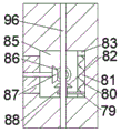
Beneficially, a rotating shaft 96 is fixedly arranged at the axis position of the driving synchronous pulley 31, a rotating cavity 85 is communicated with the rear side of the grinding slider cavity 92, an outer circular surface of the upper end of the rotating shaft 96 extends into the rotating cavity 85 to be rotatably provided with a rotating sleeve 88, a rotating sleeve bevel gear 82 fixed to the outer circular surface of the rotating sleeve 88 is arranged in the rotating cavity 85, a rotating spring cavity 81 is communicated with the right side of the rotating cavity 85, a rotating cavity electromagnet 83 is fixedly arranged on the upper side in the rotating spring cavity 81, a rotating cavity moving block 79 capable of moving up and down is arranged on the lower side of the rotating spring cavity 81, a rotating cavity spring 80 is fixedly connected between the rotating cavity moving block 79 and the rotating cavity electromagnet 83, and the left end of the rotating cavity 79 extends into the rotating cavity 85 to be rotatably connected with the rotating.
Beneficially, a driven bevel gear 87 is rotatably arranged at the left side of the rotating cavity 85, a driven shaft 72 is fixedly arranged at the axis of the driven bevel gear 87, a driven cavity 73 is arranged at the left side of the grinding slider 94, a first driving bevel gear 71 is fixedly arranged in the driven cavity 73, a receiving shaft 70 is rotatably connected between the grinding slider 94 and the grinding head 93, a receiving shaft bevel gear 69 fixed on the outer circumferential surface of the receiving shaft 70 is arranged in the driven cavity 73, the receiving shaft bevel gear 69 is meshed with the first driving bevel gear 71, and a driving motor 74 facing the axis of the grinding rotating shaft 77 is fixedly arranged in the grinding head 93 and is in power connection.
Beneficially, a sliding connecting rod 89 is fixedly arranged on the right end face of the grinding slide block 94, a sliding sleeve 90 is rotatably arranged on the right end of the sliding connecting rod 89, a sliding sleeve shaft 91 is fixedly arranged at the axis position of the sliding sleeve 90, a sliding sleeve bevel gear 84 fixed on the outer circular face of the sliding sleeve 90 is arranged in the rotating cavity 85, a second transmission bevel gear 86 is fixedly arranged on the front end face of the sliding sleeve shaft 91, the sliding sleeve bevel gear 84 is meshed with the driven bevel gear 87, and the second transmission bevel gear 86 can be meshed with the rotating sleeve bevel gear 82.
Beneficially, a moving sleeve cavity 42 is arranged on the upper side of the rotating cavity 85, an outer circular surface of the upper end of the rotating shaft 96 extends to the moving sleeve cavity 42 to rotationally arrange a moving sleeve 35, a moving sleeve bevel gear 38 fixed on the outer circular surface of the moving sleeve 35 is arranged in the moving sleeve cavity 42, a moving spring cavity 37 is communicated with the inner right side of the moving sleeve cavity 42, a moving cavity electromagnet 41 is fixedly arranged on the inner upper side of the moving spring cavity 37, a moving cavity slider 36 capable of moving up and down is arranged on the lower side of the moving spring cavity 37, a moving cavity spring 40 is fixedly connected between the moving cavity slider 36 and the moving cavity electromagnet 41, the left end of the moving cavity slider 36 extends into the moving sleeve cavity 42 to be rotationally connected with the outer circular surface of the moving sleeve 35, a third transmission bevel gear 39 is rotationally arranged on the left side of the moving sleeve cavity 42, a straight gear shaft 43 is fixedly arranged on the axis of the third transmission, remove sleeve chamber 42 left side and be equipped with straight gear chamber 46, the outer disc of straight gear shaft 43 left end extends to straight gear chamber 46 internal fixation is equipped with straight-teeth gear 45, straight gear chamber 46 downside is equipped with the rack plate 47 that can the back-and-forth movement, the fixed rack and pinion 44 that is equipped with of rack plate 47 up end, rack and pinion 44 with straight-teeth gear 45 meshes, the fixed supporting shoe 34 that is equipped with of terminal surface under rack plate 47, the supporting shoe 34 lower extreme extends to in the grinding chamber 48 with the outer disc fixed connection of grinding slider 94.
Beneficially, a synchronous belt shaft 95 is fixedly arranged at the axis of the driven synchronous pulley 24, an outer circular surface of the upper end of the synchronous belt shaft 95 extends into the lifting cavity 13 and is rotatably provided with a bearing sleeve 25, the left side of the lifting cavity 13 is communicated with a bearing spring cavity 23, a bearing cavity electromagnet 20 is fixedly arranged at the upper side in the bearing spring cavity 23, a bearing cavity moving block 22 capable of moving up and down is arranged at the lower side of the bearing spring cavity 23, the right end of the bearing cavity moving block 22 is rotatably connected with the outer circular surface of the bearing sleeve 25, a bearing cavity spring 21 is fixedly connected between the bearing cavity moving block 22 and the bearing cavity electromagnet 20, a lead screw 14 is rotatably arranged on the inner upper wall of the lifting cavity 13, the outer circular surface of the lead screw 14 is in threaded connection with the lifting block 15, and the bearing sleeve 25 can be.
Beneficially, the lifting cavity 13 is provided with a grinding fluid cavity 50 on the upper side, a spray pipe 49 communicated with the grinding fluid cavity 48 is arranged on the left side of the grinding fluid cavity 50, a water pump 12 is fixedly arranged between the spray pipe 49 and the grinding fluid cavity 50 and is communicated with the grinding fluid cavity, the cleaning cavity 33 is communicated with a door plate cavity 62 on the right side, and a door plate 61 capable of being turned rightwards is hinged in the door plate cavity 62.
The use steps herein are described in detail below with reference to fig. 1-5: in the initial operating state, the grinding carriage 94 is in the forward limit position, the replacement box 51 is in the upper limit position, and the receiving sleeve 25 is in the lower limit position.
In operation, the clamping chamber electromagnet 19 is activated to drive the upper and lower clamping plates 17 to move away from each other, a part to be ground is placed in the clamping chamber 16, the clamping chamber electromagnet 19 stops working to drive the clamping plates 17 to clamp the part, the power motor 56 is activated to drive the blade shaft 29 to rotate, the blade shaft bevel gear 58 is driven to rotate, the blade shaft bevel gear 58 engaged therewith is driven to rotate, the transmission shaft 28 is driven to rotate, the rotating synchronous pulley 27 is driven to rotate, the transmission synchronous pulley 31 wound around the synchronous pulley 26 and the rotating synchronous pulley 27 are driven to rotate, the transmission synchronous pulley 31 drives the rotating shaft 96 to rotate, the moving chamber electromagnet 41 is activated to drive the moving chamber slide block 36 to move upwards, the moving sleeve 35 is driven to move upwards, and the moving sleeve bevel gear 38 is engaged with the third transmission bevel gear 39, at this time, the rotating shaft 96 drives the moving sleeve 35 to rotate, and further drives the moving sleeve bevel gear 38 to rotate, and drives the third transmission bevel gear 39 engaged therewith to rotate, and further drives the spur gear shaft 43 to rotate, and further drives the spur gear 45 to rotate, and further drives the rack gear 44 engaged therewith to move backward, and further drives the rack plate 47 to move backward, and drives the supporting block 34 to move backward, and further drives the grinding slider 94 to move backward, and further drives the grinding head 93 to move backward, and at the same time, the transmission motor 74 is started, and further drives the grinding rotating shaft 77 to rotate, and further drives the rough machining grinding tool 65 to rotate, so that the connection is ground from front to back, and when the grinding is required from top to bottom, the receiving chamber electromagnet 20 is started, and further drives the receiving chamber moving block 22 to move upward, and further drives the receiving sleeve 25 to move upward and spline-connect with the lead screw 14, at this time, the driven synchronous pulley 24 drives the synchronous belt shaft 95 to rotate, and further drives the receiving sleeve 25 to rotate, so as to drive the screw rod 14 to rotate, thereby driving the lifting block 15 connected by the screw thread to move downwards, at this time, the rough machining grinding tool 65 grinds the connection from top to bottom, when the grinding tool needs to be replaced, the rotating chamber electromagnet 83 is started, and further the rotating chamber moving block 79 is driven to move upwards, thereby driving the rotating sleeve 88 to move upwards, and the rotating sleeve bevel gear 82 is meshed with the second transmission bevel gear 86, at this time, the rotating shaft 96 drives the rotating sleeve bevel gear 82 to rotate, and further drives the second transmission bevel gear 86 meshed therewith to rotate, and further drives the sliding sleeve 90 to rotate, thereby driving the sliding sleeve bevel gear 84 to rotate, and drives the driven bevel gear 87 meshed therewith to rotate, and further drives the driven shaft 72 to rotate, and further drives the first transmission bevel gear, thereby it rotates to drive the bearing shaft bevel gear 69 who meshes with it, and drive and bear the rotation of axle 70, and then drive grinding head 93 and rotate ninety degrees backward, make rough machining grinding apparatus 65 get back to in rough machining grinding apparatus places chamber 52 this moment, start motor 56, and then drive replacement case 51 and remove downwards, start grinding apparatus chamber electro-magnet 75, and then drive grinding apparatus fixed block 78 and remove backward, thereby fix finish machining grinding apparatus 63 and accomplish the change, meanwhile, start water pump 12, and then make the grinding fluid in grinding fluid chamber 50 get into in grinding chamber 48 through spray pipe 49 and cool off the processing part, flabellum pivot 29 drives flabellum 60 and rotates this moment, and then make the iron fillings in clearance chamber 33 get into and collect the completion in chamber 30.
The invention has the beneficial effects that: according to the invention, by fixing the part to be machined firstly and then grinding the part, the machined part is fixed through the clamping device firstly, then the rough machining grinding head is used for primarily grinding the part, and then the finish machining grinding head is actively replaced through the conversion device for finish machining, so that the grinding head is prevented from being replaced manually, time and labor are saved, convenience and rapidness are realized, when the part is machined in a large batch, a large amount of time is consumed for replacing the grinding head, the efficiency is low, in addition, the angle adjusting grinding can be carried out on the part, the part can be fully machined at each angle, the manual adjustment is not needed, and the effect is good.
The above embodiments are merely illustrative of the technical ideas and features of the present invention, and the purpose thereof is to enable those skilled in the art to understand the contents of the present invention and implement the present invention, and not to limit the protection scope of the present invention. All equivalent changes and modifications made according to the spirit of the present invention should be covered within the protection scope of the present invention.
Claims (9)
1. The utility model provides a can change metal parts machining equipment of grinding head automatically, includes the grinder, its characterized in that: a grinding cavity with a forward opening is arranged in the grinding machine, a grinding device is arranged on the right side in the grinding cavity and comprises a grinding slide block cavity communicated with the right side of the grinding cavity, a grinding slide block capable of moving back and forth is arranged in the grinding slide block cavity, a grinding head is rotatably arranged on the left side of the grinding slide block, a grinding rotating shaft is rotatably arranged in the grinding head, a grinding tool fixing cavity is arranged in the grinding rotating shaft, a grinding tool cavity electromagnet is fixedly arranged on the right side in the grinding tool fixing cavity, a grinding tool fixing block capable of moving left and right is arranged on the left side in the grinding tool fixing cavity, a grinding tool cavity spring is fixedly connected between the grinding tool fixing block and the grinding tool cavity electromagnet, a grinding tool connecting cavity is arranged in the grinding tool fixing block, a rough machining grinding tool is fixedly arranged in the grinding tool connecting cavity and can be used for, a replacement cavity electromagnet is fixedly arranged at the lower side in the replacement spring cavity, a replacement box capable of moving up and down is arranged at the upper side of the replacement spring cavity, a replacement cavity spring is fixedly connected between the replacement box and the replacement cavity electromagnet, a rough machining grinding tool placing cavity communicated with the grinding cavity is arranged in the replacement box, the rough machining grinding tool placing cavity can be used for storing the rough machining grinding tool, a finish machining grinding tool placing cavity communicated with the grinding cavity is arranged at the upper side of the rough machining grinding tool placing cavity, a finish machining grinding tool capable of moving back and forth is arranged in the finish machining grinding tool placing cavity, the finish machining grinding tool can be used for finish machining grinding of parts, a clamping device is arranged at the left side of the grinding cavity and comprises a lifting cavity communicated with the left side of the grinding cavity, a lifting block capable of moving up and down is arranged in the lifting cavity, and a clamping cavity communicated with, the clamping cavity is internally and vertically symmetrically and fixedly provided with clamping cavity electromagnets, clamping plates capable of moving up and down are arranged in the clamping cavities in an up-and-down symmetrical mode, the clamping plates are respectively fixedly connected with clamping cavity springs between the clamping cavity electromagnets from top to bottom, the clamping plates can clamp parts needing grinding, a cleaning cavity is arranged on the lower side of the grinding cavity in a communicated mode, a cleaning device is arranged on the rear side in the cleaning cavity, and the cleaning device can clean iron scraps.
2. The metal parts machining apparatus capable of automatically replacing a grinding head as set forth in claim 1, wherein: cleaning device is including locating the flabellum pivot chamber of clearance chamber rear side, flabellum pivot intracavity internal rotation is equipped with flabellum pivot bevel gear, flabellum pivot bevel gear axle center rigidity is equipped with the flabellum pivot, the outer disc of flabellum pivot front end extends to the fixed flabellum that is equipped with in clearance chamber the intercommunication of clearance chamber downside is equipped with collects the chamber, the flabellum enables the iron fillings entering of clearance intracavity collect the intracavity and collect the processing, flabellum pivot antetheca internal fixation is equipped with just to the motor power and the power connection in flabellum pivot axle center.
3. The metal parts machining apparatus capable of automatically replacing a grinding head as set forth in claim 2, wherein: the utility model discloses a synchronous belt drive device, including flabellum pivot intracavity downside, transmission shaft bevel gear axle center rigidity is equipped with the transmission shaft, flabellum pivot chamber downside is equipped with the synchronous belt chamber, the outer disc of transmission shaft lower extreme extends to the synchronous belt intracavity is fixed and is equipped with the rotation synchronous pulley, synchronous belt chamber right side is rotated and is equipped with the transmission synchronous pulley, synchronous belt chamber right side is rotated and is equipped with driven synchronous pulley, driven synchronous pulley with the transmission synchronous pulley and it has the hold-in range to rotate between the synchronous pulley jointly around.
4. A metal parts machining apparatus capable of automatically replacing a grinding head as set forth in claim 3, wherein: the fixed axis of rotation that is equipped with in transmission synchronous pulley axle center position, grinding slider chamber rear side intercommunication is equipped with rotates the chamber, the outer disc in axis of rotation upper end extends to it is equipped with the rotation sleeve to rotate the intracavity rotation, it is fixed in to rotate the intracavity the rotation sleeve bevel gear of the outer disc of rotation sleeve, it is equipped with the rotation spring chamber to rotate chamber right side intercommunication, the fixed rotation chamber electro-magnet that is equipped with of rotation spring intracavity upside, rotation spring chamber downside is equipped with the rotation chamber movable block that can reciprocate, rotate the chamber movable block with fixedly connected with rotates the chamber spring between the chamber electro-magnet, it extends to rotate chamber movable block left end rotate the intracavity with the rotation sleeve rotates and is connected.
5. The metal parts working apparatus capable of automatically replacing a grinding head as set forth in claim 4, wherein: the grinding machine is characterized in that a driven bevel gear is arranged on the left side of the rotating cavity in a rotating mode, a driven shaft is fixedly arranged in the axis of the driven bevel gear, a driven cavity is arranged on the left side of the grinding slide block, a first transmission bevel gear is fixedly arranged in the driven cavity, the grinding slide block is connected with a receiving shaft in a rotating mode between the grinding heads, a receiving shaft bevel gear fixed on the outer circular surface of the receiving shaft is arranged in the driven cavity, the receiving shaft bevel gear is meshed with the first transmission bevel gear, and the grinding heads are internally fixedly provided with a transmission motor right facing the axis of the grinding rotating shaft and are in power connection.
6. The metal parts machining apparatus capable of automatically replacing a grinding head as set forth in claim 1, wherein: the grinding slider right-hand member face is fixed and is equipped with sliding connection pole, the sliding connection pole right-hand member rotates and is equipped with sliding sleeve, sliding sleeve axle center rigidity is equipped with sliding sleeve axle, it is fixed in to rotate the intracavity sliding sleeve bevel gear of the outer disc of sliding sleeve, the fixed second transmission bevel gear that is equipped with of sliding sleeve axle front end face, sliding sleeve bevel gear with driven bevel gear meshes, second transmission bevel gear can with rotating sleeve bevel gear meshes.
7. The metal parts working apparatus capable of automatically replacing a grinding head as set forth in claim 4, wherein: a moving sleeve cavity is arranged on the upper side of the rotating cavity, the outer circular surface of the upper end of the rotating shaft extends into the moving sleeve cavity and is rotatably provided with a moving sleeve, a moving sleeve bevel gear fixed on the outer circular surface of the moving sleeve is arranged in the moving sleeve cavity, a moving spring cavity is communicated with the right side in the moving sleeve cavity, a moving cavity electromagnet is fixedly arranged on the upper side in the moving spring cavity, a moving cavity slider capable of moving up and down is arranged on the lower side of the moving spring cavity, a moving cavity spring is fixedly connected between the moving cavity slider and the moving cavity electromagnet, the left end of the moving cavity slider extends into the moving sleeve cavity and is rotatably connected with the outer circular surface of the moving sleeve, a third transmission bevel gear is rotatably arranged on the left side in the moving sleeve cavity, a straight gear shaft is fixedly arranged on the axis of the third transmission, the outer disc of straight-tooth gear axle left end extends to the straight-tooth gear intracavity is fixed and is equipped with the straight-tooth gear, straight-tooth gear chamber downside is equipped with the rack plate that can the back-and-forth movement, the fixed rack and pinion that is equipped with of rack plate up end, rack and pinion with the straight-tooth gear meshing, the fixed supporting shoe that is equipped with of terminal surface under the rack plate, the supporting shoe lower extreme extends to in the grinding chamber with the outer disc fixed connection of grinding slider.
8. A metal parts machining apparatus capable of automatically replacing a grinding head as set forth in claim 3, wherein: the synchronous belt pulley comprises a driven synchronous pulley shaft, a synchronous belt shaft is fixedly arranged on the shaft center of the driven synchronous pulley, the outer circular surface of the upper end of the synchronous belt shaft extends to a lifting cavity, a bearing sleeve is arranged in the lifting cavity in a rotating mode, a bearing spring cavity is communicated with the left side of the lifting cavity, a bearing cavity electromagnet is fixedly arranged on the upper side of the bearing spring cavity, a bearing cavity moving block capable of moving up and down is arranged on the lower side of the bearing spring cavity, the right end of the bearing cavity moving block is connected with the outer circular surface of the bearing sleeve in a rotating mode, the bearing cavity moving block is fixedly connected with a bearing cavity spring between the bearing cavity electromagnet, a lead screw is arranged on the upper wall of the lifting cavity in.
9. The metal parts machining apparatus capable of automatically replacing a grinding head as set forth in claim 1, wherein: the lift chamber upside is equipped with the grinding fluid chamber, grinding fluid chamber left side be equipped with the spray line of grinding chamber intercommunication, the spray line with fixed water pump and the intercommunication of being equipped with between the grinding fluid chamber, clearance chamber right side intercommunication is equipped with the door plant chamber, door plant intracavity hinged joint has the door plant that can overturn right.
Priority Applications (1)
| Application Number | Priority Date | Filing Date | Title |
|---|---|---|---|
| CN202011097189.2A CN112139949A (en) | 2020-10-14 | 2020-10-14 | Metal part machining equipment capable of automatically replacing grinding head |
Applications Claiming Priority (1)
| Application Number | Priority Date | Filing Date | Title |
|---|---|---|---|
| CN202011097189.2A CN112139949A (en) | 2020-10-14 | 2020-10-14 | Metal part machining equipment capable of automatically replacing grinding head |
Publications (1)
| Publication Number | Publication Date |
|---|---|
| CN112139949A true CN112139949A (en) | 2020-12-29 |
Family
ID=73953054
Family Applications (1)
| Application Number | Title | Priority Date | Filing Date |
|---|---|---|---|
| CN202011097189.2A Withdrawn CN112139949A (en) | 2020-10-14 | 2020-10-14 | Metal part machining equipment capable of automatically replacing grinding head |
Country Status (1)
| Country | Link |
|---|---|
| CN (1) | CN112139949A (en) |
Cited By (2)
| Publication number | Priority date | Publication date | Assignee | Title |
|---|---|---|---|---|
| CN112605721A (en) * | 2021-01-15 | 2021-04-06 | 上海睦翔科技有限公司 | Automatic grinding device for cutter |
| CN112643470A (en) * | 2021-01-07 | 2021-04-13 | 石家庄弘品科技有限公司 | Multi-station grinding tool machining device capable of removing dust |
-
2020
- 2020-10-14 CN CN202011097189.2A patent/CN112139949A/en not_active Withdrawn
Cited By (2)
| Publication number | Priority date | Publication date | Assignee | Title |
|---|---|---|---|---|
| CN112643470A (en) * | 2021-01-07 | 2021-04-13 | 石家庄弘品科技有限公司 | Multi-station grinding tool machining device capable of removing dust |
| CN112605721A (en) * | 2021-01-15 | 2021-04-06 | 上海睦翔科技有限公司 | Automatic grinding device for cutter |
Similar Documents
| Publication | Publication Date | Title |
|---|---|---|
| CN112139949A (en) | Metal part machining equipment capable of automatically replacing grinding head | |
| CN214445204U (en) | Automobile punching part burring device | |
| CN111775015A (en) | Automatic small parts machining equipment of polishing of replacement grinding apparatus | |
| CN216576994U (en) | Flat grinder convenient to it is clean | |
| CN215659407U (en) | A sieve grinds formula burring equipment of polishing for valve foundry goods | |
| CN216327066U (en) | Cylindrical grinding machine for precision machining | |
| CN112643470B (en) | Multi-station grinding tool machining device capable of removing dust | |
| CN210524412U (en) | A surely neat device for production of stainless steel head | |
| CN213319214U (en) | Surface grinding machine | |
| CN210588563U (en) | Special-shaped glass machining center | |
| CN220881848U (en) | Reciprocating lifting mechanism for sander | |
| CN219403685U (en) | Feeding device of bearing grinding machine | |
| CN112828718A (en) | Casting forming process for overflow valve shell | |
| CN220718918U (en) | Metal surface treatment burnishing device | |
| CN220718775U (en) | Multidirectional polisher for deep processing of glass | |
| CN212398552U (en) | Welding equipment for tank type chemical equipment | |
| CN112123161A (en) | Mechanical device for polishing curved surface | |
| CN220825759U (en) | Cast member burring equipment | |
| CN108608272B (en) | A kind of robotic deburring's equipment for improving structure | |
| CN220372812U (en) | Semi-automatic equipment for high-speed grinding of circular blade edge | |
| CN117381607B (en) | Polishing device for machining mechanical parts | |
| CN213196827U (en) | Inclination adjustable is edging machine for machining | |
| CN211439341U (en) | Machining grinding device | |
| CN216542503U (en) | Automobile gasket finishing and grinding device with overturning function | |
| CN219853915U (en) | Surface polishing mechanism for welded pipe machining |
Legal Events
| Date | Code | Title | Description |
|---|---|---|---|
| PB01 | Publication | ||
| PB01 | Publication | ||
| SE01 | Entry into force of request for substantive examination | ||
| SE01 | Entry into force of request for substantive examination | ||
| WW01 | Invention patent application withdrawn after publication |
Application publication date: 20201229 |
|
| WW01 | Invention patent application withdrawn after publication |