CN112139931A - Full-automatic abrasive belt grinding machine - Google Patents
Full-automatic abrasive belt grinding machine Download PDFInfo
- Publication number
- CN112139931A CN112139931A CN202011008738.4A CN202011008738A CN112139931A CN 112139931 A CN112139931 A CN 112139931A CN 202011008738 A CN202011008738 A CN 202011008738A CN 112139931 A CN112139931 A CN 112139931A
- Authority
- CN
- China
- Prior art keywords
- block
- seat
- linkage
- driving
- belt
- Prior art date
- Legal status (The legal status is an assumption and is not a legal conclusion. Google has not performed a legal analysis and makes no representation as to the accuracy of the status listed.)
- Granted
Links
- XEEYBQQBJWHFJM-UHFFFAOYSA-N Iron Chemical compound [Fe] XEEYBQQBJWHFJM-UHFFFAOYSA-N 0.000 claims description 64
- 229910052742 iron Inorganic materials 0.000 claims description 32
- 230000002093 peripheral effect Effects 0.000 claims description 13
- 230000000903 blocking effect Effects 0.000 claims description 7
- 230000008878 coupling Effects 0.000 claims description 5
- 238000010168 coupling process Methods 0.000 claims description 5
- 238000005859 coupling reaction Methods 0.000 claims description 5
- 238000013016 damping Methods 0.000 claims description 3
- 238000000926 separation method Methods 0.000 claims description 3
- 238000004140 cleaning Methods 0.000 claims 1
- 238000004519 manufacturing process Methods 0.000 abstract description 5
- 230000000694 effects Effects 0.000 abstract description 3
- 238000000034 method Methods 0.000 description 6
- 230000008569 process Effects 0.000 description 6
- 230000005484 gravity Effects 0.000 description 4
- 230000007246 mechanism Effects 0.000 description 4
- 238000005498 polishing Methods 0.000 description 4
- 230000009471 action Effects 0.000 description 3
- 230000009286 beneficial effect Effects 0.000 description 2
- 239000002184 metal Substances 0.000 description 2
- 229910052751 metal Inorganic materials 0.000 description 2
- 238000003825 pressing Methods 0.000 description 2
- 238000010521 absorption reaction Methods 0.000 description 1
- 230000008859 change Effects 0.000 description 1
- 229910001651 emery Inorganic materials 0.000 description 1
- 230000006872 improvement Effects 0.000 description 1
- 238000003754 machining Methods 0.000 description 1
- 230000004048 modification Effects 0.000 description 1
- 238000012986 modification Methods 0.000 description 1
- 239000011148 porous material Substances 0.000 description 1
- 230000000750 progressive effect Effects 0.000 description 1
- 230000001105 regulatory effect Effects 0.000 description 1
- 230000002441 reversible effect Effects 0.000 description 1
- 238000001179 sorption measurement Methods 0.000 description 1
- 238000004381 surface treatment Methods 0.000 description 1
- 239000002699 waste material Substances 0.000 description 1
Images


Classifications
-
- B—PERFORMING OPERATIONS; TRANSPORTING
- B24—GRINDING; POLISHING
- B24B—MACHINES, DEVICES, OR PROCESSES FOR GRINDING OR POLISHING; DRESSING OR CONDITIONING OF ABRADING SURFACES; FEEDING OF GRINDING, POLISHING, OR LAPPING AGENTS
- B24B21/00—Machines or devices using grinding or polishing belts; Accessories therefor
- B24B21/18—Accessories
- B24B21/20—Accessories for controlling or adjusting the tracking or the tension of the grinding belt
Abstract
The invention discloses a full-automatic abrasive belt grinding machine which comprises a rack and a driven belt wheel, wherein a sliding groove is formed in the rack, a sliding seat is arranged in the sliding groove, a first driving piece and a driving belt wheel are arranged on the sliding seat, an abrasive belt is sleeved between the driving belt wheel and the driven belt wheel, a linkage block is arranged in the sliding groove in a sliding mode, a driving component for driving the linkage block to reciprocate is arranged on the rack, the sliding seat and the linkage block are detachably and fixedly connected, a tensioning frame is arranged on one side of the rack, a taking-out device is arranged on the tensioning frame, a fixed seat is arranged between the taking-out device and the rack, a moving seat is arranged on the fixed seat, a third driving piece for driving the moving seat to move is arranged on the fixed seat, a clamping jaw is arranged on the moving seat. The invention has the following advantages and effects: the automatic adjustment of the tension of the abrasive belt can be realized, and the abrasive belt can be automatically replaced, so that the production cost is reduced, and the workload of workers is reduced.
Description
Technical Field
The invention relates to machining equipment, in particular to a full-automatic abrasive belt grinding machine.
Background
With the continuous improvement of the living standard of people, the requirements of people on the quality of life are higher and higher, such as for household products, the pursuit of surface quality, attractiveness and the like is pursued. Polishing is a common process for metal surface treatment, is very common in the daily product processing process, is beneficial to reducing the roughness of the metal surface and improving the grade of the product. The existing polishing equipment has various types and also has instruments suitable for polishing various special products.
The existing abrasive belt sander mainly comprises a frame, an abrasive belt, a driving belt wheel, a driven belt wheel, a motor and an adjusting mechanism for adjusting the tension of the abrasive belt, wherein the existing adjusting mechanism mainly comprises two types of manual adjustment and mechanical adjustment. The change in length of the sanding belt with the sanding process is a dynamic and progressive process, which results in that the tensioning of the sanding belt needs to be continuously adjusted during the operation of the sanding belt. The manual adjustment mode is complicated to operate, and the processing efficiency of workers is influenced; the mechanical adjustment mode needs to be provided with an additional mechanical adjustment mechanism, so that the production cost of the abrasive belt sander is greatly increased. In addition, the existing abrasive belt sander needs a worker to manually replace the abraded abrasive belt in the working process, and if the abrasive belt sander is started accidentally or by mistake touch in the abrasive belt replacing process, great potential safety hazards exist, and the life safety of the worker is affected.
Disclosure of Invention
The invention aims to provide a full-automatic abrasive belt sander, which can realize automatic adjustment and automatic replacement of abrasive belt tensioning, and has low production cost and no potential safety hazard.
The technical purpose of the invention is realized by the following technical scheme: a full-automatic abrasive belt grinding machine comprises a machine frame and a driven belt wheel which is rotatably arranged on the machine frame, wherein a sliding groove is formed in the machine frame, a sliding seat which is located below the driven belt wheel and slides in a reciprocating manner towards the driven belt wheel is arranged in the sliding groove, a first driving piece and a driving belt wheel driven by the first driving piece are arranged on the sliding seat, an abrasive belt is sleeved between the driving belt wheel and the driven belt wheel, a linkage block which moves in a reciprocating manner between the driven belt wheel and the driving belt wheel is arranged in the sliding groove in a sliding manner, a driving component which drives the linkage block to move in a reciprocating manner is arranged on the machine frame, the sliding seat and the linkage block are detachably and fixedly connected, a tensioning frame which is used for fixing the abrasive belt is arranged on one side of the machine frame, an abrasive belt taking-out device which takes out the abrasive belt one by one, the fixed seat is provided with a third driving piece for driving the moving seat to move, the moving seat is provided with a clamping jaw which slides between the rack and the tensioning frame in a reciprocating manner, and the moving seat is rotatably provided with a second screw rod in threaded connection with the clamping jaw and a fourth driving piece for driving the second screw rod to rotate.
Through adopting above-mentioned technical scheme, through setting up first driving piece and driving pulley in the slide of the mode of slide and then cooperating the slide that slides and set up, rely on first driving piece, driving pulley and slide three's gravity to realize automatically regulated to the tensioning of abrasive band, this kind of setting up mode does not need the people to go to adjust the tensioning of abrasive band in the use, also need not set up extra abrasive band tensioning adjustment mechanism to manufacturing cost has been reduced, workman's work load has been reduced.
When the emery wheel on needs are changed drive pulley and the driven pulley, move towards drive pulley through drive component drive linkage piece, carry out fixed connection with slide and linkage piece through the mode that can dismantle fixed connection, rethread drive component drives linkage piece and slide and moves towards driven pulley together for reduce drive pulley and driven pulley distance between the two, just can realize changing the abrasive band. The abrasive belts are sleeved and mounted on the tensioning frame layer by layer, and the abrasive belts are expanded and tightly abutted through the tensioning frame. The abrasive belt on the tensioning frame is taken out through the taking-out device, the abrasive belt on the taking-out device is connected through the clamping jaw, the clamping jaw is matched with the third driving piece and the fourth driving piece to move on an X axis and a Y axis, and the abrasive belt on the clamping jaw is sleeved on the driven belt wheel and the driving belt wheel; and the waste abrasive belts on the driven belt wheel and the driving belt wheel can be taken out through the clamping jaws. After a new abrasive belt is sleeved, the linkage block and the sliding seat are separated in a detachable fixed connection mode, so that the sliding seat moves back to the driven belt wheel under the action of gravity, the abrasive belt is automatically tensioned, and the replacement efficiency of the abrasive belt is improved; and realizes the automatic replacement of the abrasive belt.
Further setting the following steps: the taking-out device comprises a connecting rod, a fifth driving piece and a bearing rod, wherein the connecting rod is arranged along the abrasive belt on the tensioning frame in a radial sliding mode, the fifth driving piece drives the connecting rod to slide in a reciprocating mode, the bearing block is hinged to the connecting rod, the first spring is used for connecting the bearing block and the connecting rod to enable an opening to be formed between the bearing block and the connecting rod, the bearing rod is arranged on the connecting rod, a frosted layer is arranged on one surface, back to the connecting rod, of the bearing block, when the bearing block slides towards the abrasive belt on the tensioning frame, one end, back to the opening, of the bearing block faces the tensioning frame, when the bearing block moves to the outer circumferential wall of the abrasive belt on the tensioning frame, the frosted layer is tightly.
By adopting the technical scheme, the fifth driving piece drives the abutting block to move towards the abrasive belt on the tensioning frame, and when the abutting block slides towards the abrasive belt by setting the opening of the abutting block back to the tensioning frame, the abutting block can be abutted with the peripheral wall of the abrasive belt to drive the abutting block to inwards turn towards one side of the connecting rod, so that the abutting block smoothly slides to the peripheral wall of the abrasive belt on the tensioning frame. The connecting rod is driven by the fifth driving piece to move back to the tensioning frame, and through the friction force between the sanding layer and the outer peripheral wall of the abrasive belt and the abutting force of the abutting block abutting against the outer peripheral wall of the abrasive belt, the connecting rod moving back to the tensioning frame can take out the outermost abrasive belt on the tensioning frame, and the abrasive belt taken out falls off and is hung on the bearing rod under the action of gravity, so that the abrasive belts are taken out one by one.
Further setting the following steps: the taking-out device further comprises a movable seat arranged on the tensioning frame in a damping sliding mode in the vertical direction, a gear arranged on the movable seat in a rotating mode and a rack arranged on the tensioning frame and meshed with the gear, the connecting rod and the fifth driving piece are arranged on the movable seat, a ratchet wheel rotating along with the gear is arranged on the movable seat in a rotating mode, and a pawl which is matched with the ratchet wheel and used for driving the movable seat to drive the connecting rod to move close to the outer peripheral wall of the abrasive belt is hinged to the connecting rod.
Through adopting above-mentioned technical scheme, when supporting tight piece and moving to the position of the abrasive band periphery wall on the tensioning frame towards the tensioning frame, the pawl just contacts with the ratchet and drives the ratchet and drive the gear and rotate, makes the movable seat drive support tight piece and move towards the abrasive band periphery wall on the tensioning frame to when guaranteeing that the abrasive band quantity on the tensioning frame reduces, support tight piece also can be fine support tightly in the periphery wall of abrasive band, thereby realize stably taking out one by one the abrasive band on the tensioning frame.
Further setting the following steps: including set up in the first magnetic path of slide, set up in the linkage piece and with first magnetic path absorption and realize the second magnetic path of linkage between the slide and the linkage piece between the two and set up in the frame and be used for realizing the stopper piece of slide and the separation of linkage piece between the two.
Through adopting above-mentioned technical scheme, the linkage piece drives the second magnet and removes towards the slide, realizes linkage between the two of linkage piece and slide through the mutual adsorption effort between the two of first magnet and second magnet, when the linkage piece drives the slide and removes towards from the driven pulleys, the slide in the removal is contradicted on stopping the piece to linkage piece and slide separation between the two has been realized.
Further setting the following steps: the driving component comprises a first screw rod which is rotatably arranged on the rack and is in threaded connection with the linkage block and a second driving piece which drives the first screw rod to rotate.
Through adopting above-mentioned technical scheme, the second driving piece drives first screw rod and just reverse rotation to drive the linkage piece and realize reciprocating sliding in the spout.
Further setting the following steps: the abrasive belt conveyor is characterized in that a placing seat which reciprocates towards the outer peripheral wall of the abrasive belt and is used for placing a workpiece is arranged on the rack in a sliding mode, when the linkage block drives the sliding seat to move towards one side of the blocking block, a linkage component which drives the placing seat to move back to the abrasive belt is arranged between the linkage block and the placing seat, and a reset spring used for resetting the placing seat is arranged between the rack and the placing seat.
Through adopting above-mentioned technical scheme, the setting of placing the seat makes and treats that the processing work piece can place and carry out the operation of polishing on placing the seat, makes the operation more convenient. When the linkage block drives the sliding seat to move towards one side of the blocking block, the placing seat is driven by the linkage component to be away from the abrasive belt, the distance between the abrasive belt and the placing seat is increased, and the abrasive belt is taken out and replaced more conveniently. When the linkage block moves towards the sliding seat and stops at a linkage position which is not formed by the sliding seat, the placing seat moves towards the abrasive belt under the action of the return spring, and the placing seat is returned to the initial position.
Further setting the following steps: the linkage component is including articulating in the first yoke arm of placing the seat, articulating in the second yoke arm of first yoke arm, setting up in the waist shape hole of second yoke arm and setting up in the frame baffle that is located both one sides of first yoke arm and second yoke arm, be equipped with on the linkage piece and slide and set up in the shaft that connects in waist shape hole, work as when the linkage piece removes towards driving pulley, the shaft slides and sets up in waist shape hole and makes linkage piece and second yoke arm not constitute the linkage, work as when the linkage piece drives the slide and blocks piece one side motion, the shaft offsets with waist shape pore wall and makes linkage piece and second yoke arm constitute the linkage.
By adopting the technical scheme, when the linkage block moves towards the sliding seat, the linkage block moving towards the sliding seat does not form linkage with the second linkage arm through the arrangement of the waist-shaped hole; when the linkage block drives the sliding seat to move towards one side of the blocking block, the first linkage arm and the second linkage arm are limited by the baffle in a mode that the coupling shaft is abutted to the waist-shaped hole wall, so that linkage is formed, and the first linkage arm and the second linkage arm drive the placing seat to move back to the abrasive belt.
Further setting the following steps: the abrasive belt type iron block placing device is characterized in that a placing groove is formed in one face, facing the rack, of the placing seat, an iron block is movably arranged in the placing groove, a locating groove for the iron block to enter is formed in one face, facing the iron block, of the rack and located under an iron block moving path, when the iron block is located in the locating groove, the iron block is also located in the placing groove and used for limiting the placing seat to move, when the iron block is located in the locating groove, the placing seat is located at a position close to an abrasive belt, and a third magnetic block for driving the iron block to move into the placing groove is placed on the placing seat.
Through adopting above-mentioned technical scheme, when placing the seat and moving towards the abrasive band, the seat of placing in the removal drives the iron plate and moves towards the abrasive band together, and when the iron plate moved to the constant head tank top, the iron plate got into the constant head tank under the effect of gravity and was located the standing groove simultaneously, fixes a position the seat of placing in the removal, ensures the stability of placing the seat. When the placing seat is to be moved, the third magnetic block is only required to be placed above the placing seat, the iron block is adsorbed by the magnetic force of the third magnetic block, the iron block is separated from the positioning groove and enters the placing groove, and the moving of the placing seat is realized.
In conclusion, the invention has the following beneficial effects: the invention can realize the automatic adjustment of the tension of the abrasive belt and realize the automatic replacement of the abrasive belt, thereby reducing the production cost and the workload of workers.
Drawings
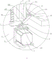
FIG. 1 is a perspective view of an embodiment;
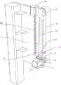
FIG. 2 is a schematic structural view of the taking-out apparatus in the embodiment;
FIG. 3 is a schematic view of the removing device in the embodiment from another perspective;
FIG. 4 is an enlarged view of portion C of FIG. 3;
FIG. 5 is a schematic top view of the removing device in the embodiment;
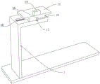
FIG. 6 is a partial perspective view of the embodiment;
FIG. 7 is a partial schematic structural view of the embodiment;
FIG. 8 is an enlarged view of portion A of FIG. 7;
FIG. 9 is another partial schematic view of the embodiment;
FIG. 10 is a partial side view of the embodiment;
FIG. 11 is an enlarged view of portion B of FIG. 10;
FIG. 12 is a partial sectional view of the embodiment;
FIG. 13 is a schematic structural view of a link member in the embodiment.
In the figure: 1. a frame; 2. a driven pulley; 3. a slide base; 4. a first driving member; 5. a driving pulley; 6. an abrasive belt; 7. a linkage block; 8. a drive member; 81. a first screw; 82. a second driving member; 9. a first magnetic block; 10. a second magnetic block; 11. a blocking block; 12. a placing seat; 13. a linkage member; 131. a first link arm; 132. a second link arm; 133. a waist-shaped hole; 134. a baffle plate; 135. coupling; 14. a return spring; 15. a placement groove; 16. an iron block; 17. positioning a groove; 18. a third magnetic block; 19. a chute; 20. a tension frame; 21. a take-out device; 211. a connecting rod; 212. a fifth driving member; 213. a propping block; 214. a first spring; 215. a bearing rod; 216. a movable seat; 217. a gear; 218. a rack; 219. a ratchet wheel; 220. a pawl; 22. a fixed seat; 23. a movable seat; 24. a third driving member; 25. a clamping jaw; 26. a second screw; 27. and a fourth driving member.
Detailed Description
The present invention will be described in further detail with reference to the accompanying drawings.
Referring to fig. 1 to 13, a full-automatic abrasive belt sander comprises a frame 1 and a driven pulley 2 rotatably disposed on the frame 1, a chute 19 vertically disposed is formed in the frame 1, a sliding seat 3 located under the driven pulley 2 and sliding back and forth towards the driven pulley 2 is slidably disposed in the chute 19, a first driving member 4 and a driving pulley 5 driven by the first driving member 4 are fixedly disposed on the sliding seat 3, and an abrasive belt 6 is sleeved between the driving pulley 5 and the driven pulley 2. The first driving part 4 is a motor, and the driving belt wheel 5 is fixedly arranged on an output shaft of the motor.
A tensioning frame 20 for fixing the abrasive belts 6 is arranged on one side of the frame 1, the abrasive belts 6 are sequentially sleeved on the tensioning frame 20 layer by layer, and the abrasive belts 6 are tightly abutted through the expansion force of the tensioning frame 20. Be equipped with on tensioning frame 20 and take out device 21 with abrasive band 6 one by one, be equipped with fixing base 22 between taking out device 21 and the frame 1, be equipped with on the fixing base 22 along the reciprocating motion seat 23 that slides of vertical direction, be equipped with the third driving piece 24 that the seat 23 removed is removed in the drive on the fixing base 22, and third driving piece 24 is the cylinder, and the cylinder body of cylinder is fixed to be set up in fixing base 22, piston rod and removes seat 23 fixed connection. The moving base 23 is provided with a clamping jaw 25 which slides back and forth between the frame 1 and the tensioning frame 20, the moving base 23 is rotatably provided with a second screw 26 connected with the clamping jaw 25 through a bearing and a fourth driving part 27 for driving the second screw 26 to rotate, the fourth driving part 27 is a motor, the motor is fixedly arranged on the moving base 23, and an output shaft of the motor is fixedly connected with the second screw 26.
The removing device 21 comprises a connecting rod 211 arranged to slide along the radial direction of the abrasive belt 6 on the tensioning frame 20, a fifth driving element 212 driving the connecting rod 211 to slide back and forth, a pressing block 213 hinged to the connecting rod 211, a first spring 214 connecting the pressing block 213 and the connecting rod 211 to form an opening therebetween, and a receiving rod 215 fixedly arranged on the connecting rod 211. One end of the first spring 214 is fixedly connected with the abutting block 213, and the other end is fixedly connected with the connecting rod 211, one surface of the abutting block 213, which faces away from the connecting rod 211, is provided with a sanding layer, and the sanding layer can be specifically sandpaper which is fixedly bonded to the abutting block 213. When the abutment block 213 slides towards the sanding belt 6 on the tensioning frame 20, the end of the abutment block 213 facing away from the opening faces the tensioning frame 20; when abutment blocks 213 are moved to correspond to the peripheral wall of sanding belt 6 on tensioning frame 20, the sanded layer abuts against the peripheral wall of sanding belt 6 and adapter 215 is located in the inner circle of sanding belt 6.
The taking-out device 21 further comprises a movable seat 216 slidably arranged on the tensioning frame 20 in a damping manner along the vertical direction, a gear 217 rotatably arranged on the movable seat 216, and a rack 218 fixedly arranged on the tensioning frame 20 and meshed with the gear 217. The connecting rod 211 is slidably disposed on the movable seat 216, the fifth driving element 212 is a cylinder, a cylinder body of the cylinder is fixedly disposed on the movable seat 216, a piston rod is fixedly connected to the connecting rod 211, a ratchet wheel 219 fixedly connected to the gear 217 is rotatably disposed on the movable seat 216, and a pawl 220, which is used for driving the movable seat 216 to drive the connecting rod 211 to move close to the outer circumferential wall of the abrasive belt 6 in cooperation with the ratchet wheel 219, is hinged to the connecting rod 211.
The sliding groove 19 is internally provided with a linkage block 7 which reciprocates between the driven belt wheel 2 and the driving belt wheel 5 in a sliding way, the frame 1 is provided with a driving component 8 which drives the linkage block 7 to reciprocate, and the sliding seat 3 and the linkage block 7 are fixedly connected in a detachable way. The driving member 8 includes a first screw 81 rotatably disposed on the frame 1 through a bearing and threadedly coupled to the linkage block 7, and a second driving member 82 for driving the first screw 81 to rotate. The axial direction of the first screw 81 is parallel to the length direction of the sliding groove 19, and the first screw 81 passes through the linkage block 7 to be in threaded connection with the linkage block; the second driving member 82 is a motor, and the motor is fixedly disposed on the frame 1 and has an output shaft fixedly connected to the first screw 81.
The sliding seat 3 is fixedly provided with a first magnetic block 9, the linkage block 7 is fixedly provided with a second magnetic block 10 which is mutually adsorbed with the first magnetic block 9 and realizes linkage between the sliding seat 3 and the linkage block 7, the machine frame 1 is fixedly provided with a stop block 11 above the sliding seat 3, and when the sliding seat 3 moves upwards, the sliding seat 3 can be abutted against the stop block 11 to limit the upward movement of the sliding seat 3.
The frame 1 is provided with a placing seat 12 which moves towards the outer peripheral wall of the abrasive belt 6 in a reciprocating manner and is used for placing a workpiece, when the linkage block 7 drives the sliding seat 3 to move towards one side of the blocking block 11, a linkage component 13 which drives the placing seat 12 to move back to the abrasive belt 6 is arranged between the linkage block 7 and the placing seat 12, a reset spring 14 for resetting the placing seat 12 is arranged between the frame 1 and the placing seat 12, one end of the reset spring 14 is fixedly connected with the frame 1, and the other end of the reset spring is fixedly connected with the placing seat 12.
The linkage member 13 includes a first linkage arm 131 hinged to the placing seat 12, a second linkage arm 132 hinged to the first linkage arm 131, a waist-shaped hole 133 formed in the second linkage arm 132, and a baffle 134 fixedly disposed on the frame 1 and located on one side of the first linkage arm 131 and the second linkage arm 132, a linkage shaft 135 slidably disposed in the waist-shaped hole 133 is fixedly disposed on the linkage block 7, when the linkage block 7 moves toward the driving pulley 5, the linkage shaft 135 slidably disposed in the waist-shaped hole 133 enables the linkage block 7 and the second linkage arm 132 not to form linkage, and when the linkage block 7 drives the sliding seat 3 to move toward the side of the blocking block 11, the linkage shaft 135 and the waist-shaped hole 133 abut against each other to enable the linkage block 7 and the second linkage arm 132 to form linkage.
Placing seat 12 has seted up standing groove 15 towards the one side of frame 1, and the activity is provided with iron plate 16 in standing groove 15, and frame 1 just is located iron plate 16 moving path and offers the constant head tank 17 that supplies iron plate 16 to get into towards the one side of iron plate 16, and when iron plate 16 was located constant head tank 17, iron plate 16 also was located standing groove 15 simultaneously and was used for restricting placing seat 12 and removes, and when iron plate 16 was located constant head tank 17, placing seat 12 was located the position that is close to abrasive band 6, placed the third magnetic path 18 that the drive iron plate 16 removed into standing groove 15 on placing seat 12, and when iron plate 16 was located standing groove 15, iron plate 16 was located constant head tank 17 top.
The present embodiment is only for explaining the present invention, and it is not limited to the present invention, and those skilled in the art can make modifications of the present embodiment without inventive contribution as needed after reading the present specification, but all of them are protected by patent law within the scope of the claims of the present invention.
Claims (8)
1. The utility model provides a full-automatic abrasive band polisher, includes frame (1) and rotates and sets up in driven pulleys (2) of frame (1), its characterized in that: a sliding groove (19) is formed in the rack (1), a sliding seat (3) which is located below the driven belt wheel (2) and slides towards the driven belt wheel (2) in a reciprocating mode is arranged in the sliding groove (19), a first driving piece (4) and a driving belt wheel (5) driven by the first driving piece (4) are arranged on the sliding seat (3), an abrasive belt (6) is sleeved between the driving belt wheel (5) and the driven belt wheel (2), a linkage block (7) which moves in a reciprocating mode between the driven belt wheel (2) and the driving belt wheel (5) is arranged in the sliding groove (19) in a sliding mode, a driving component (8) which drives the linkage block (7) to move in a reciprocating mode is arranged on the rack (1), and the sliding seat (3) and the linkage block (7) are fixedly connected in a detachable mode; the abrasive belt conveyor is characterized in that a tensioning frame (20) used for fixing an abrasive belt (6) is arranged on one side of the rack (1), a taking-out device (21) used for taking out the abrasive belt (6) one by one is arranged on the tensioning frame (20), a fixed seat (22) is arranged between the taking-out device (21) and the rack (1), a moving seat (23) which slides in a reciprocating mode along the vertical direction is arranged on the fixed seat (22), a third driving piece (24) used for driving the moving seat (23) to move is arranged on the fixed seat (22), a clamping jaw (25) which slides in a reciprocating mode between the rack (1) and the tensioning frame (20) is arranged on the moving seat (23), and a second screw rod (26) in threaded connection with the clamping jaw (25) and a fourth driving piece (27) used for driving the second screw rod (26) to rotate are arranged.
2. A fully automatic sanding belt (6) sander according to claim 1, characterized by: the taking-out device (21) comprises a connecting rod (211) which is arranged along the radial direction of the abrasive belt (6) on the tensioning frame (20) in a sliding way, a fifth driving piece (212) which drives the connecting rod (211) to slide back and forth, a propping block (213) which is hinged with the connecting rod (211), a first spring (214) which connects the propping block (213) and the connecting rod (211) to form an opening between the propping block and the connecting rod (211) and a bearing rod (215) which is arranged on the connecting rod (211), one surface of the abutting block (213) back to the connecting rod (211) is provided with a frosted layer, when the abutment block (213) is slid towards the sanding belt (6) on the tensioning frame (20), one end of the abutting block (213) back to the opening faces the tensioning frame (20), when the abutment block (213) is moved to correspond to the peripheral wall of the sanding belt (6) on the tensioning frame (20), the sanding layer is tightly abutted against the outer peripheral wall of the sanding belt (6), and the carrying rod (215) is positioned at the inner ring of the sanding belt (6).
3. A fully automatic sanding belt (6) sander according to claim 2, characterized by: the taking-out device (21) further comprises a movable seat (216) which is arranged on the tensioning frame (20) in a damping sliding mode along the vertical direction, a gear (217) which is arranged on the movable seat (216) in a rotating mode and a rack (218) which is arranged on the tensioning frame (20) and meshed with the gear (217), the connecting rod (211) and the fifth driving piece (212) are both arranged on the movable seat (216), a ratchet wheel (219) which rotates along with the gear (217) is arranged on the movable seat (216) in a rotating mode, and a pawl (220) which is matched with the ratchet wheel (219) and used for driving the movable seat (216) to drive the connecting rod (211) to move close to the peripheral wall of the abrasive belt (6) is hinged to the.
4. The full-automatic belt sander of claim 1, wherein: including set up in first magnetic path (9) of slide (3), set up in linkage block (7) and adsorb and realize second magnetic path (10) of linkage between slide (3) and linkage block (7) and set up in frame (1) and be used for realizing stopping piece (11) of separation between slide (3) and linkage block (7) with first magnetic path (9).
5. The full-automatic belt sander of claim 1, wherein: the driving component (8) comprises a first screw rod (81) which is rotatably arranged on the rack (1) and is in threaded connection with the linkage block (7) and a second driving piece (82) which drives the first screw rod (81) to rotate.
6. The full-automatic belt sander of claim 1, wherein: the abrasive belt cleaning machine is characterized in that a placing seat (12) which moves towards the outer peripheral wall of an abrasive belt (6) and is used for placing a workpiece is arranged on the machine frame (1) in a sliding mode, when the linkage block (7) drives the sliding seat (3) to move towards one side of the blocking block (11), a linkage component (13) which drives the placing seat (12) to move back to the abrasive belt (6) is arranged between the linkage block (7) and the placing seat (12), and a reset spring (14) which is used for resetting the placing seat (12) is arranged between the machine frame (1) and the placing seat (12).
7. The full-automatic belt sander of claim 6, wherein: the linkage component (13) comprises a first connecting arm (131) hinged to the placing seat (12), a second connecting arm (132) hinged to the first connecting arm (131), a waist-shaped hole (133) arranged on the second connecting arm (132) and a baffle (134) arranged on the side, located on the first connecting arm (131) and the second connecting arm (132), of the rack (1), a coupling shaft (135) which is arranged on the waist-shaped hole (133) in a sliding way is arranged on the linkage block (7), when the linkage block (7) moves towards the driving belt wheel (5), the coupling shaft (135) is arranged in the waist-shaped hole (133) in a sliding manner, so that the linkage block (7) and the second linkage arm (132) are not linked, when the linkage block (7) drives the sliding seat (3) to move towards one side of the stop block (11), the coupling shaft (135) abuts against the wall of the waist-shaped hole (133) to enable the linkage block (7) and the second linkage arm (132) to form linkage.
8. The full-automatic belt sander of claim 6, wherein: one side, facing the rack (1), of the placing seat (12) is provided with a placing groove (15), an iron block (16) is movably arranged in the placing groove (15), one side, facing the iron block (16), of the rack (1) is provided with a positioning groove (17) for the iron block (16) to enter, the iron block (16) is also located in the placing groove (15) and used for limiting the placing seat (12) to move when the iron block (16) is located in the positioning groove (17), the placing seat (12) is located at a position close to the abrasive belt (6) when the iron block (16) is located in the positioning groove (17), and a third magnetic block (18) for driving the iron block (16) to move into the placing groove (15) is placed on the placing seat (12).
Priority Applications (1)
| Application Number | Priority Date | Filing Date | Title |
|---|---|---|---|
| CN202011008738.4A CN112139931B (en) | 2020-09-23 | 2020-09-23 | Full-automatic abrasive belt grinding machine |
Applications Claiming Priority (1)
| Application Number | Priority Date | Filing Date | Title |
|---|---|---|---|
| CN202011008738.4A CN112139931B (en) | 2020-09-23 | 2020-09-23 | Full-automatic abrasive belt grinding machine |
Publications (2)
| Publication Number | Publication Date |
|---|---|
| CN112139931A true CN112139931A (en) | 2020-12-29 |
| CN112139931B CN112139931B (en) | 2021-11-23 |
Family
ID=73897665
Family Applications (1)
| Application Number | Title | Priority Date | Filing Date |
|---|---|---|---|
| CN202011008738.4A Active CN112139931B (en) | 2020-09-23 | 2020-09-23 | Full-automatic abrasive belt grinding machine |
Country Status (1)
| Country | Link |
|---|---|
| CN (1) | CN112139931B (en) |
Cited By (4)
| Publication number | Priority date | Publication date | Assignee | Title |
|---|---|---|---|---|
| CN112809516A (en) * | 2021-01-12 | 2021-05-18 | 南京远大船舶附件有限公司 | Hole site grinding device is used in boats and ships accessory processing with bent angle wainscot mechanism |
| CN113263406A (en) * | 2021-06-10 | 2021-08-17 | 杨凤云 | Intelligent chemical part polishing device |
| CN114734347A (en) * | 2022-06-13 | 2022-07-12 | 烟台大学 | Intelligent mechanical arm exoskeleton metal polishing and spraying integrated processing device |
| CN115056096A (en) * | 2022-08-16 | 2022-09-16 | 睢宁盛浩金属工具有限公司 | Polishing equipment suitable for processing curved metal workpiece |
Citations (13)
| Publication number | Priority date | Publication date | Assignee | Title |
|---|---|---|---|---|
| US3153306A (en) * | 1962-08-27 | 1964-10-20 | Hammond Machinery Builders Inc | Belt abrader |
| JPH058166A (en) * | 1991-06-28 | 1993-01-19 | Mitsubishi Heavy Ind Ltd | Automatic belt replacing device for automatic wing belt polisher |
| JP2000108006A (en) * | 1998-10-06 | 2000-04-18 | Ishikawajima Harima Heavy Ind Co Ltd | Belt changing mechanism of belt grinding device |
| KR20010027482A (en) * | 1999-09-14 | 2001-04-06 | 이구택 | Device for changing a grinding belt of a strip grinder |
| JP2001219352A (en) * | 2000-02-09 | 2001-08-14 | Nippon Steel Corp | Belt replacing device for steel strip grinder |
| DE202009004809U1 (en) * | 2008-12-11 | 2009-07-09 | Almi Machinefabriek B.V. | Pipe grinding machine with adjustable side guide of the sanding belt |
| CN204686573U (en) * | 2015-06-01 | 2015-10-07 | 汕头市三三智能科技有限公司 | A kind of cutter polishing machine |
| CN106625137A (en) * | 2017-03-03 | 2017-05-10 | 东莞市铁犀智能科技有限公司 | Sanding belt automatic replacing device of belt sander |
| CN206795495U (en) * | 2017-05-12 | 2017-12-26 | 诸暨市固特安机械有限公司 | A kind of belt sander |
| JP2019155541A (en) * | 2018-03-14 | 2019-09-19 | アミテック株式会社 | Belt sanding machine |
| CN209477936U (en) * | 2019-01-26 | 2019-10-11 | 高盈表业(深圳)有限公司 | A kind of steel watchcase sander convenient for adjusting |
| CN210281785U (en) * | 2019-08-20 | 2020-04-10 | 永康市凌城达机械设备制造有限公司 | Abrasive belt replacing mechanism |
| CN210909399U (en) * | 2019-10-09 | 2020-07-03 | 浙江好运木业有限公司 | Sanding machine sand skin tensioning adjusting device |
-
2020
- 2020-09-23 CN CN202011008738.4A patent/CN112139931B/en active Active
Patent Citations (13)
| Publication number | Priority date | Publication date | Assignee | Title |
|---|---|---|---|---|
| US3153306A (en) * | 1962-08-27 | 1964-10-20 | Hammond Machinery Builders Inc | Belt abrader |
| JPH058166A (en) * | 1991-06-28 | 1993-01-19 | Mitsubishi Heavy Ind Ltd | Automatic belt replacing device for automatic wing belt polisher |
| JP2000108006A (en) * | 1998-10-06 | 2000-04-18 | Ishikawajima Harima Heavy Ind Co Ltd | Belt changing mechanism of belt grinding device |
| KR20010027482A (en) * | 1999-09-14 | 2001-04-06 | 이구택 | Device for changing a grinding belt of a strip grinder |
| JP2001219352A (en) * | 2000-02-09 | 2001-08-14 | Nippon Steel Corp | Belt replacing device for steel strip grinder |
| DE202009004809U1 (en) * | 2008-12-11 | 2009-07-09 | Almi Machinefabriek B.V. | Pipe grinding machine with adjustable side guide of the sanding belt |
| CN204686573U (en) * | 2015-06-01 | 2015-10-07 | 汕头市三三智能科技有限公司 | A kind of cutter polishing machine |
| CN106625137A (en) * | 2017-03-03 | 2017-05-10 | 东莞市铁犀智能科技有限公司 | Sanding belt automatic replacing device of belt sander |
| CN206795495U (en) * | 2017-05-12 | 2017-12-26 | 诸暨市固特安机械有限公司 | A kind of belt sander |
| JP2019155541A (en) * | 2018-03-14 | 2019-09-19 | アミテック株式会社 | Belt sanding machine |
| CN209477936U (en) * | 2019-01-26 | 2019-10-11 | 高盈表业(深圳)有限公司 | A kind of steel watchcase sander convenient for adjusting |
| CN210281785U (en) * | 2019-08-20 | 2020-04-10 | 永康市凌城达机械设备制造有限公司 | Abrasive belt replacing mechanism |
| CN210909399U (en) * | 2019-10-09 | 2020-07-03 | 浙江好运木业有限公司 | Sanding machine sand skin tensioning adjusting device |
Cited By (6)
| Publication number | Priority date | Publication date | Assignee | Title |
|---|---|---|---|---|
| CN112809516A (en) * | 2021-01-12 | 2021-05-18 | 南京远大船舶附件有限公司 | Hole site grinding device is used in boats and ships accessory processing with bent angle wainscot mechanism |
| CN112809516B (en) * | 2021-01-12 | 2023-02-28 | 南京远大船舶附件有限公司 | Hole site grinding device is used in boats and ships accessory processing with bent angle wainscot mechanism |
| CN113263406A (en) * | 2021-06-10 | 2021-08-17 | 杨凤云 | Intelligent chemical part polishing device |
| CN114734347A (en) * | 2022-06-13 | 2022-07-12 | 烟台大学 | Intelligent mechanical arm exoskeleton metal polishing and spraying integrated processing device |
| CN114734347B (en) * | 2022-06-13 | 2022-08-26 | 烟台大学 | Intelligent mechanical arm exoskeleton metal polishing and spraying integrated processing device |
| CN115056096A (en) * | 2022-08-16 | 2022-09-16 | 睢宁盛浩金属工具有限公司 | Polishing equipment suitable for processing curved metal workpiece |
Also Published As
| Publication number | Publication date |
|---|---|
| CN112139931B (en) | 2021-11-23 |
Similar Documents
| Publication | Publication Date | Title |
|---|---|---|
| CN112139931B (en) | Full-automatic abrasive belt grinding machine | |
| CN106425818A (en) | Polishing equipment for industrial steel pipe | |
| CN206029538U (en) | Suppress formula plane grinder | |
| CN112296824A (en) | Abrasive belt grinding device | |
| CN108177060A (en) | A kind of rotatable double-station belt sander | |
| CN110394730A (en) | A kind of industrial robot sanding and polishing equipment and its application method | |
| CN111975560A (en) | Automatic grinding device | |
| CN110919505A (en) | Multi-angle grinding device | |
| CN108381316A (en) | Auto-parts grinding device | |
| CN112139932B (en) | Tensioning automatic adjustment abrasive belt grinding machine | |
| CN207915177U (en) | A kind of rotatable double-station belt sander | |
| CN210281840U (en) | Vertical polishing machine for vacuum cup | |
| CN214603694U (en) | Burnishing device is used in valve processing | |
| CN112045549B (en) | Automatic polishing equipment for mold | |
| CN114131508A (en) | Abrasive cloth recycling and polishing machine | |
| CN210281802U (en) | Polishing machine | |
| CN210819082U (en) | Automatic multi-station numerical control wire drawing machine | |
| CN210060695U (en) | High-efficient grinding device is used in mechanical production | |
| CN219094673U (en) | Full-automatic polishing equipment | |
| CN110948341A (en) | Grinding machine | |
| CN110815140A (en) | Novel machining workbench | |
| CN210281841U (en) | Burnishing machine of thermos cup | |
| CN213945962U (en) | Abrasive belt grinding device | |
| CN214265081U (en) | Polishing assembly of precision grinding machine | |
| CN218613400U (en) | Workpiece grinding device |
Legal Events
| Date | Code | Title | Description |
|---|---|---|---|
| PB01 | Publication | ||
| PB01 | Publication | ||
| SE01 | Entry into force of request for substantive examination | ||
| SE01 | Entry into force of request for substantive examination | ||
| GR01 | Patent grant | ||
| GR01 | Patent grant | ||
| TR01 | Transfer of patent right |
Effective date of registration: 20220831 Address after: 325000 Dongou Industrial Park, Oubei Town, Yongjia County, Wenzhou City, Zhejiang Province Patentee after: ZHEJIANG CANAAN TECHNOLOGY Ltd. Address before: 325000 Wenzhou City National University Science Park incubator, No. 38 Dongfang South Road, Ouhai District, Wenzhou, Zhejiang Patentee before: WENZHOU VOCATIONAL & TECHNICAL College |
|
| TR01 | Transfer of patent right |