CN112108859B - Automatic feeding machine for screw locking - Google Patents
Automatic feeding machine for screw locking Download PDFInfo
- Publication number
- CN112108859B CN112108859B CN202010970558.8A CN202010970558A CN112108859B CN 112108859 B CN112108859 B CN 112108859B CN 202010970558 A CN202010970558 A CN 202010970558A CN 112108859 B CN112108859 B CN 112108859B
- Authority
- CN
- China
- Prior art keywords
- screw
- collecting box
- screws
- material collecting
- automatic feeding
- Prior art date
- Legal status (The legal status is an assumption and is not a legal conclusion. Google has not performed a legal analysis and makes no representation as to the accuracy of the status listed.)
- Active
Links
- 239000000463 material Substances 0.000 claims abstract description 38
- 238000007599 discharging Methods 0.000 claims abstract description 28
- 238000007873 sieving Methods 0.000 claims abstract description 11
- 238000012216 screening Methods 0.000 claims description 14
- 230000005540 biological transmission Effects 0.000 claims description 4
- 230000007246 mechanism Effects 0.000 abstract description 11
- 238000004519 manufacturing process Methods 0.000 abstract description 5
- 230000006872 improvement Effects 0.000 description 9
- 238000000034 method Methods 0.000 description 3
- 230000008569 process Effects 0.000 description 3
- 238000012163 sequencing technique Methods 0.000 description 2
- 230000009471 action Effects 0.000 description 1
- 230000009286 beneficial effect Effects 0.000 description 1
- 230000000903 blocking effect Effects 0.000 description 1
- 230000007547 defect Effects 0.000 description 1
- 238000007726 management method Methods 0.000 description 1
- 238000012986 modification Methods 0.000 description 1
- 230000004048 modification Effects 0.000 description 1
- 230000001360 synchronised effect Effects 0.000 description 1
Images


Classifications
-
- B—PERFORMING OPERATIONS; TRANSPORTING
- B23—MACHINE TOOLS; METAL-WORKING NOT OTHERWISE PROVIDED FOR
- B23P—METAL-WORKING NOT OTHERWISE PROVIDED FOR; COMBINED OPERATIONS; UNIVERSAL MACHINE TOOLS
- B23P19/00—Machines for simply fitting together or separating metal parts or objects, or metal and non-metal parts, whether or not involving some deformation; Tools or devices therefor so far as not provided for in other classes
- B23P19/001—Article feeders for assembling machines
-
- B—PERFORMING OPERATIONS; TRANSPORTING
- B23—MACHINE TOOLS; METAL-WORKING NOT OTHERWISE PROVIDED FOR
- B23P—METAL-WORKING NOT OTHERWISE PROVIDED FOR; COMBINED OPERATIONS; UNIVERSAL MACHINE TOOLS
- B23P19/00—Machines for simply fitting together or separating metal parts or objects, or metal and non-metal parts, whether or not involving some deformation; Tools or devices therefor so far as not provided for in other classes
- B23P19/04—Machines for simply fitting together or separating metal parts or objects, or metal and non-metal parts, whether or not involving some deformation; Tools or devices therefor so far as not provided for in other classes for assembling or disassembling parts
- B23P19/06—Screw or nut setting or loosening machines
Landscapes
- Engineering & Computer Science (AREA)
- Mechanical Engineering (AREA)
- Feeding Of Articles To Conveyors (AREA)
Abstract
The invention discloses an automatic screw locking feeder, which comprises a bracket and a conveying belt arranged on the bracket, wherein the bracket is also provided with a material collecting box and a material discharging plate, the material collecting box is arranged above the inlet end of the conveying belt, two groups of material sieving plates are arranged in the material collecting box, the two groups of material sieving plates are rotatably arranged in the material collecting box through a rotating motor and rotate in opposite directions, and blanking spaces are formed between the two groups of material sieving plates for screws to pass through one by one; the discharging plate is obliquely arranged at the outlet end of the conveying belt and used for discharging the screws outwards; the conveyer belt is provided with a plurality of holes of placing along direction of delivery, and a plurality of holes of placing are evenly distributed, place the hole and set up to the diameter slightly to be greater than the screw diameter and be less than the screw head diameter. The automatic screw locking machine disclosed by the invention can finish orderly arrangement and conveying of screws at lower cost on the whole, can be butted with mechanisms such as an automatic screw locking machine and the like to grab the screws to finish subsequent screw locking, can replace manpower to finish automatic product processing, liberates labor force and improves production efficiency.
Description
Technical Field
The invention relates to the technical field of feeding machines, in particular to an automatic feeding machine for a screw locking device.
Background
The screw locking device is an automatic application specific device which uses an automatic mechanism to replace hands to finish taking, placing and screwing screws, and can also be used for automatically assembling columnar small parts by slightly changing, wherein the automatic feeding machine carries out automatic feeding and is convenient for locking the screws. The existing automatic feeding machine cannot uniformly feed screw materials, the feeding speed is uncontrollable, the guiding cannot be adjusted in height in the feeding process, and the application range is limited.
Disclosure of Invention
Aiming at the defects in the prior art, the invention aims to provide the automatic screw locking feeding machine which can convey screws in order and can take materials in order in the following screw locking process.
In order to achieve the purpose, the invention provides the following technical scheme: the screw locking automatic feeding machine comprises a support, a conveying belt arranged on the support, a material collecting box and a material discharging plate, wherein the material collecting box and the material discharging plate are arranged on the support; the discharging plate is obliquely arranged at the outlet end of the conveying belt and used for discharging the screws outwards; the conveyer belt is provided with a plurality of holes of placing along direction of delivery, and a plurality of holes of placing are evenly distributed, place the hole and set up to the diameter slightly to be greater than the screw diameter and be less than the screw head diameter.
As an improvement, an inclined plate is arranged at the opening part of the material collecting box, a bearing platform is arranged at the outlet of the lower end of the inclined plate, an enclosing wall is arranged at the periphery of the bearing platform, a discharge hole matched with the size of the screw is formed in one side of the bearing platform, a pair of parallel slide rails are arranged below the discharge hole, the space between the pair of slide rails is used for containing the screw and enabling the screw to slide and convey, and the discharging space between the two sets of sieve plates corresponds to the lower part of the outlet end of the pair of slide rails.
As an improvement, the inlet ends of a pair of slide rails are connected to form a circular ring, the middle part of the circular ring is provided with a stop column, and the space between the stop column and the circular ring is used for accommodating a screw; the positions of the circular ring and the baffle column are just opposite to the lower part of the discharge hole.
As an improvement, a pair of slide rails is obliquely arranged.
As an improvement, the screening plate comprises a plurality of sub-plates which are uniformly arranged along the circumference, arc-shaped grooves are formed in multiple sides of each sub-plate, and when the sub-plates of the two sets of screening plates move to the opposite blanking space, the corresponding arc-shaped grooves of the sub-plates are used for screws to pass through and are hung on the sub-plates by screw heads.
As an improvement, a driving shaft, a driven shaft and a linkage shaft are further rotatably arranged in the material collecting box, one group of screening plates are arranged on the driving shaft, the driving shaft is connected with a rotating motor for driving, one end of the driving shaft is connected with one end of the driven shaft through a transmission chain, the other group of screening plates are arranged on the linkage shaft, the linkage shaft is in linkage with the driven shaft through gear meshing, and the two groups of screening plates rotate synchronously and rotate reversely.
As an improvement, the upper end of the discharge plate is rotatably arranged on the support, the lower part of the discharge plate is hinged with an adjusting screw rod, the support is also provided with a U-shaped clamping groove for the adjusting screw rod to pass through, and nuts for limiting are arranged on the upper side and the lower side of the U-shaped clamping groove after the adjusting screw rod passes through the U-shaped clamping groove.
As an improvement, the upper part of the discharging plate is provided with an arc-shaped groove for bearing and sliding the screw.
As an improvement, the bottom of the support is fixedly connected with four support rods which are distributed in a rectangular shape, and the bottom of each support rod is in threaded connection with an adjusting bottom pad.
As an improvement, the two ends of the support are rotatably connected with driving wheels, one end of the driving wheel on one side is connected with a driving motor, the driving wheels on the two ends are wound with an annular conveying belt, a base plate is arranged on the support, and the base plate is located in the annular conveying belt.
The invention has the beneficial effects that: through the arrangement of the sieve plates in the material collecting box, workers can realize one-by-one blanking after placing batches of screws, so that the screws can fall to the conveying belt one by one, the screws at the material collecting box are received through the placing holes uniformly formed in the conveying belt, the screws can be conveyed to the discharging plate one by one, and the discharging plate can be butted with mechanisms such as an automatic screw locking machine to capture the screws to complete subsequent screw locking; the screw orderly arranging and conveying is integrally completed with lower cost, automatic product processing can be completed instead of manpower, labor force is liberated, and production efficiency is improved.
Drawings
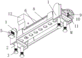
FIG. 1 is a first perspective view of the present invention;
FIG. 2 is a schematic perspective view of the present invention;
FIG. 3 is a schematic perspective view of a screen plate of the present invention;
FIG. 4 is an enlarged view at M in FIG. 2;
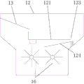
fig. 5 is a schematic longitudinal sectional view of the material collecting box of the present invention.
Fig. 6 is a schematic top view of the structure of the carriage platform and the slide rail according to the present invention.
Detailed Description
The following detailed description of specific embodiments of the invention refers to the accompanying drawings.
As shown in fig. 1-6, which is a specific embodiment of the screw locking automatic feeding machine of the present invention, the present embodiment includes a support 1 and a conveying belt 6 disposed on the support 1, the support 1 is further provided with a collecting box 12 and a discharging plate 9, the collecting box 12 is disposed above an inlet end of the conveying belt 6, two sets of sifting plates 16 are disposed in the collecting box 12, the two sets of sifting plates 16 are rotatably disposed in the collecting box 12 through a rotating motor 18 and rotate in opposite directions, and blanking spaces are formed between the two sets of sifting plates 16 for screws to pass through one by one; the discharging plate 9 is obliquely arranged at the outlet end of the conveying belt 6 and used for discharging screws outwards; the conveyer belt 6 is provided with a plurality of placing holes 7 along the direction of delivery, and a plurality of placing holes 7 are evenly distributed, and placing holes 7 set up to the diameter slightly is greater than the screw diameter and is less than the screw head diameter.
When the automatic screw placing and sorting machine is used, the whole machine is arranged at the preorder position of the automatic screw locking machine, the automatic screw feeding and locking machine, the automatic screw locking machine and other machines to place, sort and convey screws, and the automatic screw placing and sorting machine is suitable for various types of fasteners with large-top-small-bottom structures, such as screws, bolts and the like. After a worker puts a batch of screws into the material collecting box 12, when the screws fall to the two groups of material sieving plates 16, the screws are blocked by the material sieving plates 16, the two groups of material sieving plates 16 are driven by the rotating motor 18 to synchronously rotate, one screw can fall, at the moment, one placing hole 7 in the conveying belt 6 corresponds to the lower part of the blanking space to receive one screw, and after the screws are received, the conveying belt 6 moves to the next empty placing hole 7 to receive the screws; the big end of the screw reaching the output end of the conveyer belt 6 falls towards the discharging plate 9, is guided to a subsequent station by the discharging plate 9, and can be clamped and conveyed by a subsequent mechanism. The screw sorting and conveying device has the advantages that the ordered sorting and conveying of screws are completed with lower structural manufacturing cost, the automatic product processing can be completed instead of manual work, the labor force is liberated, and the production efficiency is improved.
As an improved embodiment, the mouth of the material collecting box 12 is provided with an inclined plate 13, the outlet at the lower end of the inclined plate 13 is provided with a bearing platform 121, the periphery of the bearing platform 121 is provided with a surrounding wall 122, one side of the bearing platform is provided with a discharge port 123 matched with the size of a screw, a pair of parallel slide rails 124 is arranged below the discharge port 123, the space between the pair of slide rails 124 is used for accommodating the screw and enabling the screw to slide and convey, and the lower part of the outlet end of the pair of slide rails 124 corresponds to the blanking space between the two sets of sieve plates 16.
As shown in fig. 5, before the screws fall into the blanking space between the two sets of material sieving plates 16, the screws are orderly stored and are pre-arranged and conveyed through the above structure; the workers can directly pour batch screws from the inclined plate 13, and the screws can reach the bearing platform 121 along the inclined plate 13 for storage. The bearing platform 121 can preferably set a certain slope, the lower part of the slope corresponds to the discharge port 123, the bearing screws with good limit at other positions are limited by the enclosing wall 122, the size of the discharge port 123 is matched with the screws so that the screws can be discharged singly to complete the sequencing management; the supporting platform 121 may preferably be provided with a vibrator, so that the screw can effectively complete the movement and discharge to the discharge port 123 by vibration, and the interruption of the conveying or the blockage of the discharge port 123 when the material is less can be avoided. The space between the pair of slide rails 124 can accommodate screws, the screw heads are limited on the pair of slide rails 124, the screws can slide along the slide rails 124 to the outlet end and fall to the blanking space between the two sets of sieve plates 16, and single ordered discharging is realized.
As a modified embodiment, the inlet ends of a pair of sliding rails 124 are connected to form a circular ring 125, a stop column 126 is arranged in the middle of the circular ring 125, and the space between the stop column 126 and the circular ring 125 is used for accommodating a screw; the ring 125 and the pin 126 are positioned just below the outlet 123.
As shown in fig. 6, when a screw falls to an inlet end of a pair of slide rails 124, the upper and lower positions of the screw body and the screw head are uncertain, and after the stop pillar 126 and the ring 125 are arranged, the screw body receives the falling screw in the whole space, the screw body falls to the space between the stop pillar 126 and the ring 125, the screw head is limited by the stop pillar 126 and the ring 125, and then the screw can slide to the space between the pair of slide rails 124 and be conveyed to an outlet end. The structure well supports the screws, and the arrangement and the conveying of the screws are realized.
As a modified embodiment, a pair of slide rails 124 are provided obliquely.
As shown in fig. 5, a pair of slide rails 124 is further disposed in an inclined manner on the basis of the above embodiment, so that the screw can be conveyed more smoothly and prevented from being jammed.
As an improved specific implementation mode, the screening plate 16 comprises a plurality of sub-plates which are uniformly arranged along the circumference, arc-shaped grooves 17 are formed in multiple sides of each sub-plate, and when the sub-plates of the two groups of screening plates 16 move to the opposite positions of the blanking space, the corresponding arc-shaped grooves 17 of the sub-plates are used for screws to pass through and are suspended at the sub-plates by screw heads.
As shown in fig. 3 and 5, preferably, the number of the daughter boards is 6 or 8, two opposite daughter boards in the blanking space are used for blocking screws reaching the screen plate 16, the screw bodies of the daughter boards are suspended at the daughter boards through the arc-shaped grooves 17, the up-and-down position correspondence of the screws is realized, after the screen plates 16 in the 6-piece and 8-piece structures rotate by 60 degrees and 45 degrees respectively, the screws are dropped into the placing holes 7 of the conveyor belt 6 for conveying, the next group of daughter boards continue to receive the next screws, the overall structure is simple, and the one-by-one sequencing conveying of the screws is effectively realized.
As an improved specific embodiment, a driving shaft 14, a driven shaft 15 and a linkage shaft 161 are further rotatably arranged in the material collecting box 12, one group of material sieving plates 16 is arranged on the driving shaft 14, the driving shaft 14 is connected with a rotating motor 18 for driving, one end of the driving shaft 14 is connected with one end of the driven shaft 15 through a transmission chain 19, the other group of material sieving plates 16 is arranged on the linkage shaft 161, and the linkage shaft 161 is linked with the driven shaft 15 through gear engagement, so that the two groups of material sieving plates 16 synchronously rotate and reversely rotate.
As shown in fig. 1 and 3, when the driving shaft 14 is driven by the rotating motor 18 to rotate counterclockwise, the driven shaft 15 is connected with the transmission chain 19 of the driving shaft 14 to synchronously rotate counterclockwise, and the corresponding linkage shaft 161 is engaged with the gear of the driven shaft 15 to synchronously rotate clockwise, so that the two groups of sieve plates 16 rotate in opposite directions, synchronous action and corresponding rotation are well realized, the cost is low, and the structural arrangement is reasonable.
As an improved specific implementation mode, the upper end of the discharging plate 9 is rotatably arranged on the bracket 1, the lower part of the discharging plate 9 is hinged with an adjusting screw rod 10, the bracket 1 is also provided with a U-shaped clamping groove 11 for the adjusting screw rod 10 to pass through, and nuts 101 for limiting are arranged on the upper side and the lower side of the U-shaped clamping groove 11 after the adjusting screw rod 10 passes through the U-shaped clamping groove 11.
As shown in fig. 2 and 4, a discharging plate 9 and an adjusting mechanism are further rotatably arranged to control and adjust the speed and angle of screw blanking, or to better connect different subsequent mechanisms; when concrete debugging, earlier through the nut 101 of manual rotation upside or downside after, the angle of relaxable slope, then can make out flitch 9 lower hem or last pendulum, after adjusting required position, adjust the nut 101 of downside or upside again and make two nuts 101 clip the upper and lower end of U-shaped draw-in groove 11 again, realize fixedly, its debugging is simple and convenient, and structure low in manufacturing cost.
As a modified embodiment, the upper part of the discharging plate 9 is provided with an arc-shaped groove 91 for bearing and sliding the screw.
As shown in fig. 4, the arc-shaped groove 91 forms a good guiding structure for the screw to slide down, and the arcs on both sides can be well matched with the arc of the screw head for limiting.
As a modified specific implementation mode, the bottom of the bracket 1 is fixedly connected with four support rods 2 which are distributed in a rectangular shape, and the bottom of each support rod 2 is in threaded connection with an adjusting bottom pad 3.
As shown in fig. 1 and 2, the setting mode of the supporting rod 2 and the adjusting base pad 3 provides a certain height for the whole mechanism, the adjusting base pad 3 provides a certain buffer for the mechanism, the structure is more stable to be placed, and the height can be adjusted through the threaded connection between the supporting rod 2 and the adjusting base pad 3, so that the height of different mechanisms in the subsequent sequence can be adapted to be used, and the mechanism can be adapted to other mechanisms.
As a modified embodiment, both ends of the bracket 1 are rotatably connected with driving wheels 4, one end of one side of the driving wheel 4 is connected with a driving motor 5, the driving wheels 4 at both ends are wound with an annular conveying belt 6, a backing plate 8 is arranged on the bracket 1, and the backing plate 8 is positioned inside the annular conveying belt 6.
As shown in fig. 1 and 2, the conveyer belt 6 is set to be annular by two groups of driving wheels 4, the upper conveyer belt 6 forms a flat surface to receive screws, the backing plate 8 arranged in the middle provides support for the screws placed on the upper conveyer belt 6, and when the screws reach the outlet end, the screws extrude the placing holes 7 and fall to the discharging plate 9 in the rotating process by virtue of the driving wheels 4 at the end and the backing plate 8 in the middle, so that good blanking is realized.
The above description is only a preferred embodiment of the present invention, and the protection scope of the present invention is not limited to the above embodiments, and all technical solutions belonging to the idea of the present invention belong to the protection scope of the present invention. It should be noted that modifications and embellishments within the scope of the invention may occur to those skilled in the art without departing from the principle of the invention, and are considered to be within the scope of the invention.
Claims (8)
1. Automatic feeding machine is paid to screw lock, including support (1) and set up conveyer belt (6) on support (1), its characterized in that: the automatic screw screening machine is characterized by further comprising a material collecting box (12) and a material discharging plate (9) which are arranged on the support (1), wherein the material collecting box (12) is arranged above the inlet end of the conveying belt (6), two groups of screening plates (16) are arranged in the material collecting box (12), the two groups of screening plates (16) are rotatably arranged in the material collecting box (12) through a rotating motor (18) and rotate in the opposite direction, and blanking spaces are formed between the two groups of screening plates (16) for screws to pass through one by one; the discharging plate (9) is obliquely arranged at the outlet end of the conveying belt (6) and used for discharging screws outwards; the conveying belt (6) is provided with a plurality of placing holes (7) along the conveying direction, the placing holes (7) are uniformly distributed, and the diameter of each placing hole (7) is slightly larger than the diameter of a screw and smaller than the diameter of a screw head;
an inclined plate (13) is arranged at the opening part of the material collecting box (12), a bearing platform (121) is arranged at the outlet at the lower end of the inclined plate (13), a surrounding wall (122) is arranged at the periphery of the bearing platform (121), a discharge hole (123) matched with the size of the screw is formed in one side of the bearing platform, a pair of sliding rails (124) which are arranged in parallel is arranged below the discharge hole (123), the space between the pair of sliding rails (124) is used for accommodating the screw and enabling the screw to be conveyed in a sliding manner, and the blanking space between the two groups of sieving plates (16) is corresponding to the lower part of the outlet end of the pair of sliding rails (124);
the inlet ends of the pair of sliding rails (124) are connected to form a circular ring (125), a stop column (126) is arranged in the middle of the circular ring (125), and a space between the stop column (126) and the circular ring (125) is used for accommodating a screw; the positions of the circular ring (125) and the baffle column (126) are just opposite to the lower part of the discharge hole (123).
2. The screw locking automatic feeding machine according to claim 1, characterized in that: the pair of slide rails (124) is obliquely arranged.
3. The screw-locking automatic feeding machine according to claim 1 or 2, characterized in that: the sieve flitch (16) are including arranging the even multi-disc daughter board that forms along the circumference, the multi-side of daughter board all is provided with arc wall (17), and when the daughter board of two sets of sieve flitchs (16) moved to blanking space department relatively, the corresponding arc wall (17) of daughter board was used for the screw to pass through and hangs in daughter board department by the screw head.
4. The screw-locking automatic feeding machine according to claim 1 or 2, characterized in that: the material collecting box is characterized in that a driving shaft (14), a driven shaft (15) and a linkage shaft (161) are further rotatably arranged in the material collecting box (12), a group of screening plates (16) are arranged on the driving shaft (14), the driving shaft (14) is connected with a rotating motor (18) to drive, one ends of the driving shaft (14) and the driven shaft (15) are connected through a transmission chain (19), the other group of screening plates (16) are arranged on the linkage shaft (161), the linkage shaft (161) is in gear engagement with the driven shaft (15), and the two groups of screening plates (16) are synchronously rotated and reversely rotated.
5. The screw-locking automatic feeding machine according to claim 1 or 2, characterized in that: the upper end of the discharging plate (9) is rotatably arranged on the support (1), the lower part of the discharging plate (9) is hinged with an adjusting screw rod (10), the support (1) is further provided with a U-shaped clamping groove (11) for the adjusting screw rod (10) to pass through, and the adjusting screw rod (10) passes through the U-shaped clamping groove (11) and then is provided with nuts (101) for limiting in the upper side and the lower side of the U-shaped clamping groove (11).
6. The screw-locking automatic feeding machine according to claim 1 or 2, characterized in that: the upper part of the discharging plate (9) is provided with an arc-shaped groove (91) for bearing and sliding of the screw.
7. The screw-locking automatic feeding machine according to claim 1 or 2, characterized in that: the bottom fixedly connected with of support (1) four rectangle distribution bracing pieces (2), the bottom threaded connection of bracing piece (2) has adjustment heelpiece (3).
8. The screw-locking automatic feeding machine according to claim 1 or 2, characterized in that: the both ends of support (1) are rotated and are connected with drive wheel (4), one side the one end of drive wheel (4) is connected with driving motor (5), winds on both ends drive wheel (4) and establishes annular conveyer belt (6), be provided with backing plate (8) on support (1), this backing plate (8) are located conveyer belt (6) annular inside.
Priority Applications (1)
| Application Number | Priority Date | Filing Date | Title |
|---|---|---|---|
| CN202010970558.8A CN112108859B (en) | 2020-09-15 | 2020-09-15 | Automatic feeding machine for screw locking |
Applications Claiming Priority (1)
| Application Number | Priority Date | Filing Date | Title |
|---|---|---|---|
| CN202010970558.8A CN112108859B (en) | 2020-09-15 | 2020-09-15 | Automatic feeding machine for screw locking |
Publications (2)
| Publication Number | Publication Date |
|---|---|
| CN112108859A CN112108859A (en) | 2020-12-22 |
| CN112108859B true CN112108859B (en) | 2021-10-08 |
Family
ID=73803100
Family Applications (1)
| Application Number | Title | Priority Date | Filing Date |
|---|---|---|---|
| CN202010970558.8A Active CN112108859B (en) | 2020-09-15 | 2020-09-15 | Automatic feeding machine for screw locking |
Country Status (1)
| Country | Link |
|---|---|
| CN (1) | CN112108859B (en) |
Families Citing this family (1)
| Publication number | Priority date | Publication date | Assignee | Title |
|---|---|---|---|---|
| CN113979089B (en) * | 2021-11-20 | 2022-06-24 | 安徽品优电池有限公司 | Lithium cell concentrator transport mechanism |
Citations (10)
| Publication number | Priority date | Publication date | Assignee | Title |
|---|---|---|---|---|
| CN101357434A (en) * | 2007-08-02 | 2009-02-04 | 甲府精鋲株式会社 | Screw supplying device |
| JP2013151053A (en) * | 2012-01-26 | 2013-08-08 | Kofu Seibyo Co Ltd | Screw feeder |
| CN105666118A (en) * | 2016-04-16 | 2016-06-15 | 吉林大学 | Screw multi-channel automatic feeding and installing integrated machine |
| CN106112430A (en) * | 2016-07-22 | 2016-11-16 | 苏州全丰精密机械有限公司 | Double-slider screw feeding transmission mechanism |
| CN107089376A (en) * | 2017-06-02 | 2017-08-25 | 浙江鼎业机械设备有限公司 | A kind of packaging bag conveying mechanism of paper diaper automatic packaging machine |
| CN107756021A (en) * | 2017-11-08 | 2018-03-06 | 亿和精密工业(苏州)有限公司 | A kind of self-action the screwed lock machine |
| CN107935795A (en) * | 2017-05-27 | 2018-04-20 | 湖北凯龙化工集团股份有限公司 | A kind of emulsion seismic charge Pretreatment Line |
| JP2018070328A (en) * | 2016-10-28 | 2018-05-10 | 日東精工株式会社 | Parts feeder |
| CN207671151U (en) * | 2017-12-15 | 2018-07-31 | 苏州领裕电子科技有限公司 | A kind of profile nut feeding device |
| CN209491500U (en) * | 2018-11-12 | 2019-10-15 | 东莞市博贝自动化科技有限公司 | A kind of screw automatic delivering mechanism of automatic locking screw machine |
-
2020
- 2020-09-15 CN CN202010970558.8A patent/CN112108859B/en active Active
Patent Citations (10)
| Publication number | Priority date | Publication date | Assignee | Title |
|---|---|---|---|---|
| CN101357434A (en) * | 2007-08-02 | 2009-02-04 | 甲府精鋲株式会社 | Screw supplying device |
| JP2013151053A (en) * | 2012-01-26 | 2013-08-08 | Kofu Seibyo Co Ltd | Screw feeder |
| CN105666118A (en) * | 2016-04-16 | 2016-06-15 | 吉林大学 | Screw multi-channel automatic feeding and installing integrated machine |
| CN106112430A (en) * | 2016-07-22 | 2016-11-16 | 苏州全丰精密机械有限公司 | Double-slider screw feeding transmission mechanism |
| JP2018070328A (en) * | 2016-10-28 | 2018-05-10 | 日東精工株式会社 | Parts feeder |
| CN107935795A (en) * | 2017-05-27 | 2018-04-20 | 湖北凯龙化工集团股份有限公司 | A kind of emulsion seismic charge Pretreatment Line |
| CN107089376A (en) * | 2017-06-02 | 2017-08-25 | 浙江鼎业机械设备有限公司 | A kind of packaging bag conveying mechanism of paper diaper automatic packaging machine |
| CN107756021A (en) * | 2017-11-08 | 2018-03-06 | 亿和精密工业(苏州)有限公司 | A kind of self-action the screwed lock machine |
| CN207671151U (en) * | 2017-12-15 | 2018-07-31 | 苏州领裕电子科技有限公司 | A kind of profile nut feeding device |
| CN209491500U (en) * | 2018-11-12 | 2019-10-15 | 东莞市博贝自动化科技有限公司 | A kind of screw automatic delivering mechanism of automatic locking screw machine |
Also Published As
| Publication number | Publication date |
|---|---|
| CN112108859A (en) | 2020-12-22 |
Similar Documents
| Publication | Publication Date | Title |
|---|---|---|
| CN110732486B (en) | Shell sieving mechanism | |
| CN208758090U (en) | A kind of mixing nut automatic sorting device | |
| CN206763408U (en) | A kind of fruit sorting device | |
| CN107051886A (en) | A kind of fruit sorting device | |
| CN209853148U (en) | Aggregate conveying device | |
| CN112108859B (en) | Automatic feeding machine for screw locking | |
| CN109132357A (en) | The sorting device of conveying-type is carried out to logistics transportation part | |
| CN208134670U (en) | A kind of nut automated packaging equipment | |
| CN207293450U (en) | A kind of accurate conveying device of slender piece | |
| CN112934591A (en) | Automatic device for screening, feeding, drawing and placing paint and use method | |
| CN108249124A (en) | The accurate conveying device and its carrying method of a kind of slender piece | |
| CN210824490U (en) | Semi-finished product screening and conveying device for bearing tapered roller | |
| CN215354604U (en) | Stone powder vibrating screen device for machine-made sand conveying belt | |
| CN215099943U (en) | Integrated system is transported in material quality testing | |
| CN215046478U (en) | Quick belt material loading machine of smallclothes | |
| CN112275360B (en) | Raw material batching station with stable batching function | |
| CN112027609B (en) | Yarn section of thick bamboo charging mechanism | |
| CN211613454U (en) | Shell sieving mechanism | |
| CN112173457A (en) | Hopper anti-blocking belt conveyor | |
| CN220837752U (en) | Tooth rubbing feeding device | |
| CN118083525B (en) | Wire drawing machine loading attachment | |
| CN214729964U (en) | Aquatic product processing feed divider | |
| CN220975627U (en) | Automatic material distributing system for pipe bars | |
| CN113562435B (en) | High-efficient collator of medicinal bottle plug | |
| CN217626428U (en) | Material conveying device for catalytic reduction of complex biological pollutants |
Legal Events
| Date | Code | Title | Description |
|---|---|---|---|
| PB01 | Publication | ||
| PB01 | Publication | ||
| SE01 | Entry into force of request for substantive examination | ||
| SE01 | Entry into force of request for substantive examination | ||
| GR01 | Patent grant | ||
| GR01 | Patent grant |