CN112079108A - Municipal works construction is with pressing from both sides formula pipeline handling device - Google Patents
Municipal works construction is with pressing from both sides formula pipeline handling device Download PDFInfo
- Publication number
- CN112079108A CN112079108A CN202010856399.9A CN202010856399A CN112079108A CN 112079108 A CN112079108 A CN 112079108A CN 202010856399 A CN202010856399 A CN 202010856399A CN 112079108 A CN112079108 A CN 112079108A
- Authority
- CN
- China
- Prior art keywords
- fixedly connected
- plate
- screw rod
- sliding
- bevel gear
- Prior art date
- Legal status (The legal status is an assumption and is not a legal conclusion. Google has not performed a legal analysis and makes no representation as to the accuracy of the status listed.)
- Pending
Links
Images


Classifications
-
- B—PERFORMING OPERATIONS; TRANSPORTING
- B65—CONVEYING; PACKING; STORING; HANDLING THIN OR FILAMENTARY MATERIAL
- B65G—TRANSPORT OR STORAGE DEVICES, e.g. CONVEYORS FOR LOADING OR TIPPING, SHOP CONVEYOR SYSTEMS OR PNEUMATIC TUBE CONVEYORS
- B65G47/00—Article or material-handling devices associated with conveyors; Methods employing such devices
- B65G47/74—Feeding, transfer, or discharging devices of particular kinds or types
- B65G47/90—Devices for picking-up and depositing articles or materials
Abstract
The invention relates to the technical field of municipal construction machinery, in particular to a clamp type pipeline carrying device for municipal engineering construction, which comprises a bottom plate, wherein the positions of four corners of the bottom end of the bottom plate are fixedly connected with first universal wheels, the right front side and the right rear side of the top end of the bottom plate are fixedly connected with a supporting column, the right end of the supporting column is provided with a sliding chute, a sliding block is arranged in the sliding chute and is in sliding fit with the sliding chute, the top end of the sliding block is provided with a first threaded hole which longitudinally penetrates through the sliding chute, a first screw rod is screwed in the first threaded hole, the bottom end of the first screw rod is rotatably connected with the bottom end of the sliding chute through a first bearing, and the top end of the first screw rod is rotatably connected with; it can follow ground and directly step up fixedly to the pipeline, can step up the pipeline of different diameters simultaneously, can step up two points of pipeline simultaneously, has improved the stationarity of pipeline transport, has improved its security and the practicality of using, has improved the efficiency of transport.
Description
Technical Field
The invention relates to the technical field of municipal construction machinery, in particular to a clamp type pipeline carrying device for municipal engineering construction.
Background
As is well known, municipal facilities in China refer to various buildings, structures, equipment and the like which are arranged in planning and construction ranges of urban areas and towns (villages) and provide paid or unpaid public products and services for residents based on government responsibilities and obligations.
The invention patent with the Chinese patent number of CN107539771A discloses a clamp type pipeline carrying device for municipal engineering construction, which comprises a supporting seat, wherein two sides of the lower end of the supporting seat are connected with a walking frame, the middle parts of two ends of the supporting seat are connected with rotating columns, two sides of the upper end of the supporting seat are connected with hydraulic cylinders, the upper ends of the hydraulic cylinders are connected with hydraulic shafts, and the upper ends of the hydraulic shafts are connected with carrying boxes; it is realizing getting the clamp of pipeline when using, has also reduced municipal constructor's intensity of labour simultaneously, has satisfied the needs of municipal construction pipeline transport.
The above prior art solutions still have the following drawbacks: when the pipeline is conveyed, a worker is required to convey the pipeline to a position between the left clamping block and the right clamping block to clamp and fix the pipeline, the pipeline cannot be directly clamped and fixed from the ground, the labor intensity of the worker is increased, certain potential safety hazards exist in the conveying process of the worker, the conveying speed is low, and the conveying efficiency is reduced.
Disclosure of Invention
Technical problem to be solved
Aiming at the defects of the prior art, the invention provides a clamp type pipeline carrying device for municipal engineering construction.
(II) technical scheme
In order to achieve the purpose, the invention provides the following technical scheme: a clamp type pipeline carrying device for municipal engineering construction comprises a base plate, wherein first universal wheels are fixedly connected to the positions of four corners of the bottom end of the base plate, pillars are fixedly connected to the front right side and the rear right side of the top end of the base plate, sliding grooves are formed in the right ends of the pillars, sliding blocks are arranged inside the sliding grooves and are in sliding fit with the sliding grooves, first threaded holes which longitudinally penetrate through the top ends of the sliding blocks are formed in the sliding grooves, first screw rods are screwed inside the first threaded holes, the bottom ends of the first screw rods are rotatably connected with the bottom ends of the sliding grooves through first bearings, the top ends of the first screw rods are rotatably connected with the top ends of the sliding grooves through second bearings, first motors are fixedly connected to the top ends of the pillars, the output ends of the first motors are fixedly connected with one ends of the first screw rods, the ends of the first screw rods extend to the positions above the pillars, supporting rods are fixedly connected, the left end of the first support plate is in sliding fit with the right end of the pillar, the right side of the bottom end of the support rod is fixedly connected with a second support plate, the bottom side between the first support plate and the second support plate is fixedly connected with a slide rod, a second screw rod is arranged between the first support plate and the second support plate on the upper side of the slide rod, the right end of the second screw rod is rotatably connected with the left end of the second support plate through a third bearing, the spiral directions of the threads of the left end and the right end of the second screw rod are opposite, the outer sides of the left end and the right end of the second screw rod are respectively in threaded connection with a first fixing plate and a second fixing plate, the first fixing plate and the second fixing plate are respectively provided with a circular groove which transversely penetrates, the circular grooves are in sliding fit with the slide rod, the bottom end of the first fixing plate and the bottom end of the second fixing plate are respectively and fixedly connected with a first clamping plate and a second clamping plate, the left end of second screw rod extends to the right side of transmission structure and connects, and the second screw rod rotates through fourth bearing and first support plate to be connected, the left side fixedly connected with second motor on the top of bracing piece, the output fixedly connected with pivot of second motor, the bottom of pivot extend to the inside of first extension board and be connected with the top of transmission structure, the pivot rotates with first support plate and bracing piece to be connected, the electronic jar of right side fixedly connected with of the bottom of bracing piece, the left end of electronic jar and the right-hand member fixed connection of second extension board, the bottom fixedly connected with second universal wheel of electronic jar.
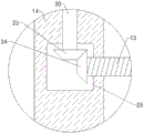
Preferably, the transmission structure comprises a first bevel gear and a second bevel gear, a square groove is formed in the first support plate, the first bevel gear is arranged on the upper side of the inside of the square groove, the top end of the first bevel gear is fixedly connected with the bottom end of the rotating shaft, a second bevel gear is arranged on the right side of the inside of the square groove, the right end of the second bevel gear is fixedly connected with the left end of the second screw rod, and the second bevel gear is meshed with the first bevel gear.
Preferably, the bottom sides of the left ends of the two pillars are fixedly connected with connecting plates, and the bottom ends of the connecting plates are fixedly connected with the top end of the bottom plate.
Preferably, the inside of the left front side and the inside of the left rear side of the bottom plate are both in threaded connection with a third screw, and the bottom end of the third screw extends to the lower part of the bottom plate and is rotatably connected with a support.
Preferably, the top end of the third screw is fixedly connected with a rotating handle.
Preferably, a plurality of fixed teeth are uniformly and fixedly connected to the bottom end of the support.
Preferably, the left side of the top end of the bottom plate is fixedly connected with a balancing weight.
Preferably, the right end of the first clamping plate and the left end of the second clamping plate are fixedly connected with anti-slip pads.
(III) advantageous effects
Compared with the prior art, the invention provides a clamp type pipeline carrying device for municipal engineering construction, which has the following beneficial effects:
1. the clamp type pipeline carrying device for municipal engineering construction drives the first screw rod to rotate through the first motor, the first screw rod rotates to enable the sliding block to slide up and down in the sliding groove, so that the heights of the first clamping plate and the second clamping plate are adjusted, the first clamping plate and the second clamping plate are arranged on one side of the device, so that the pipeline can be directly fastened and fixed from the ground, the rotating shaft is driven to rotate through the second motor, the rotating shaft drives the first conical gear to rotate, the first conical gear drives the second conical gear to rotate, the second conical gear drives the second screw rod to rotate, the second screw rod rotates to adjust the distance between the first fixing plate and the second fixing plate, so that the distance between the first clamping plate and the second clamping plate is adjusted, the pipelines with different diameters are fastened and fixed through the first clamping plate and the second clamping plate, and therefore the device can directly fasten and fix the pipeline from the ground, meanwhile, the pipeline with different diameters can be tightened, two points of the pipeline can be tightened simultaneously, the stability of pipeline transportation is improved, the safety and the practicability of the pipeline transportation are improved, and the efficiency of transportation is improved.
2. This formula of pressing from both sides pipeline handling device is used in municipal works construction changes through rotatory the messenger third screw rod and rotates to make the support move down, insert the inside on ground through fixed tooth and fix the device, promote the second universal wheel through electronic jar simultaneously and move down, make the bottom and the ground contact of second universal wheel and support the device, stability when the improvement is to pipeline handling.
3. This municipal works construction is with pressing from both sides formula pipeline handling device prevents to take place to turn on one's side through the balancing weight in to pipeline handling, improves the stationarity of device.
Drawings
FIG. 1 is a schematic cross-sectional view of the present invention;
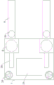
FIG. 2 is a schematic view of the overall structure of the present invention;
FIG. 3 is a schematic top view of the present invention;
FIG. 4 is an enlarged schematic view of the invention at A of FIG. 1;
fig. 5 is an enlarged schematic view of the structure at B in fig. 1 according to the present invention.
In the figure: 1. a base plate; 2. a first universal wheel; 3. a pillar; 4. a chute; 5. a slider; 6. a first threaded hole; 7. a first screw; 8. a first motor; 9. a support bar; 10. a first support plate; 11. a second support plate; 12. a slide bar; 13. a second screw; 14. a first fixing plate; 15. a second fixing plate; 16. a circular groove; 17. a first splint; 18. a second splint; 19. a second motor; 20. a rotating shaft; 21. an electric cylinder; 22. a second universal wheel; 23. a first bevel gear; 24. a second bevel gear; 25. a square groove; 26. a connecting plate; 27. a third screw; 28. a support; 29. turning a handle; 30. fixing teeth; 31. a balancing weight; 32. a non-slip mat.
Detailed Description
The technical solutions in the embodiments of the present invention will be clearly and completely described below with reference to the drawings in the embodiments of the present invention, and it is obvious that the described embodiments are only a part of the embodiments of the present invention, and not all of the embodiments. All other embodiments, which can be derived by a person skilled in the art from the embodiments given herein without making any creative effort, shall fall within the protection scope of the present invention.
Examples
Referring to fig. 1-5, a clip type pipeline carrying device for municipal engineering construction comprises a base plate 1, wherein four corners of the bottom end of the base plate 1 are fixedly connected with first universal wheels 2, the device is moved by the first universal wheels 2 rolling on the ground, a pillar 3 is fixedly connected to each of the right front side and the right rear side of the top end of the base plate 1, a chute 4 is arranged at the right end of the pillar 3, a slide block 5 is arranged inside the chute 4, the slide block 5 is in sliding fit with the chute 4, a first threaded hole 6 longitudinally penetrating is arranged at the top end of the slide block 5 inside the chute 4, a first screw 7 is screwed inside the first threaded hole 6, the bottom end of the first screw 7 is rotatably connected with the bottom end of the chute 4 through a first bearing, the top end of the first screw 7 is rotatably connected with the top end of the chute 4 through a second bearing, a first motor 8 is fixedly connected with the top end of the pillar, the first motor 8 drives the first screw 7 to rotate, the first screw 7 rotates to enable the sliding block 5 to slide up and down in the sliding groove 4, so that the heights of the first clamping plate 17 and the second clamping plate 18 are adjusted, the output end of the first motor 8 is fixedly connected with one end, extending to the upper side of the pillar 3, of the first screw 7, the right end of the sliding block 5 is fixedly connected with a supporting rod 9, the left side of the bottom end of the supporting rod 9 is fixedly connected with a first supporting plate 10, the left end of the first supporting plate 10 is in sliding fit with the right end of the pillar 3, the right side of the bottom end of the supporting rod 9 is fixedly connected with a second supporting plate 11, a sliding rod 12 is fixedly connected to the bottom side between the first supporting plate 10 and the second supporting plate 11, a second screw 13 is arranged on the upper side of the sliding rod 12 between the first supporting plate 10 and the second supporting plate 11, the right end of the second screw 13 is rotatably connected with the left end of the second supporting plate 11 through a third, the outer sides of the left end and the right end of the second screw 13 are respectively in threaded connection with a first fixing plate 14 and a second fixing plate 15, the first fixing plate 14 and the second fixing plate 15 are respectively provided with a circular groove 16 which transversely penetrates through, the circular groove 16 is in sliding fit with the slide rod 12, the bottom end of the first fixing plate 14 and the bottom end of the second fixing plate 15 are respectively and fixedly connected with a first clamping plate 17 and a second clamping plate 18, the first clamping plate 17 is arranged at the front side of the second clamping plate 18, the first supporting plate 10 is internally provided with a transmission structure, the left end of the second screw 13 extends to the right side of the transmission structure to be connected, the second screw 13 is rotatably connected with the first supporting plate 10 through a fourth bearing, the left side of the top end of the supporting rod 9 is fixedly connected with a second motor 19, the output end of the second motor 19 is fixedly connected with a rotating shaft 20, the bottom end of the rotating shaft 20 extends to the inside of, pivot 20 rotates with first extension board 10 and bracing piece 9 to be connected, the electronic jar 21 of right side fixedly connected with of the bottom of bracing piece 9, the left end of electronic jar 21 and the right-hand member fixed connection of second extension board 11, the bottom fixedly connected with second universal wheel 22 of electronic jar 21 promote the second universal wheel 22 through electronic jar 21 simultaneously and move down, make the bottom and the ground contact of second universal wheel 22 and support the device, improve the stability when carrying the pipeline.
It should be further noted that the transmission structure includes a first bevel gear 23 and a second bevel gear 24, a square groove 25 is disposed inside the first support plate 10, a first bevel gear 23 is disposed on an upper side inside the square groove 25, a top end of the first bevel gear 23 is fixedly connected to a bottom end of the rotating shaft 20, a second bevel gear 24 is disposed on a right side inside the square groove 25, a right end of the second bevel gear 24 is fixedly connected to a left end of the second screw 13, the second bevel gear 24 is engaged with the first bevel gear 23, the rotating shaft 20 is driven to rotate by the second motor 19, the rotating shaft 20 drives the first bevel gear 23 to rotate, the first bevel gear 23 drives the second bevel gear 24 to rotate, the second bevel gear 24 drives the second screw 13 to rotate, the second screw 13 rotates to adjust a distance between the first fixing plate 14 and the second fixing plate 15, so as to adjust a distance between the first clamping plate 17 and the second clamping plate 18, the pipelines with different diameters are fastened and fixed through a first clamping plate 17 and a second clamping plate 18, the bottom sides of the left ends of the two pillars 3 are fixedly connected with a connecting plate 26, the bottom end of the connecting plate 26 is fixedly connected with the top end of the bottom plate 1, the stability of the connection of the pillars 3 and the bottom plate 1 is improved, the inner parts of the left front side and the left rear side of the bottom plate 1 are in threaded connection with third screw rods 27, the bottom ends of the third screw rods 27 extend to the lower part of the bottom plate 1 and are in rotating connection with a support 28, the top end of the third screw rods 27 is fixedly connected with a rotating handle 29, the bottom end of the support 28 is uniformly and fixedly connected with a plurality of fixed teeth 30, the third screw rods 27 are rotated through the rotating handle 29, the support 28 moves downwards, the fixed teeth 30 are inserted into the ground to fix the device, the stability of pipeline lifting is improved, and the left side of the top end, prevent through balancing weight 31 that it turns on one's side to take place in the pipeline handling, improve the stationarity of device, the equal fixedly connected with slipmat 32 in right-hand member of first splint 17 and the left end of second splint 18 increases the frictional force between first splint 17 and second splint 18 and the pipeline, prevents the pipeline landing, improves the pipeline and fastens fixed stability.
The models of the first motor 8 and the second motor 19 are respectively Z2BLD25-24GN and BPY-132M-4, the first motor 8 and the second motor 19 are all known devices directly purchased from the market and used by people skilled in the art, and here we only use them, and do not improve them in structure and function, and we will not describe here in detail, and the first motor 8 and the second motor 19 are both provided with control switches matched with them, and the installation positions of the control switches are selected according to actual use requirements, so that the operators can conveniently perform operation control.
In summary, when the clip type pipeline carrying device for municipal engineering construction is used, the clip type pipeline carrying device for municipal engineering construction is firstly moved to the left side of a pipeline by rolling the first universal wheel 2 on the ground, the first clamping plate 17 and the second clamping plate 18 are moved to the upper side of the pipeline, the third screw 27 is rotated by rotating the rotating handle 29 clockwise, the support 28 is moved downwards, the device is fixed by inserting the fixed teeth 30 into the ground, then the first motor 8 is started, the first screw 7 is rotated by the first motor 8, the slide block 5 is slid downwards in the slide groove 4 by the rotation of the first screw 7, the first clamping plate 17 and the second clamping plate 18 are lowered to the two sides of the pipeline, and then the second universal wheel 22 is pushed downwards by the electric cylinder 21 at the same time, so that the bottom end of the second universal wheel 22 is in contact with the ground and supports the device, then the second motor 19 is started, the second motor 19 drives the rotating shaft 20 to rotate, the rotating shaft 20 drives the first bevel gear 23 to rotate, the first bevel gear 23 drives the second bevel gear 24 to rotate, the second bevel gear 24 drives the second screw 13 to rotate, the second screw 13 rotates to adjust the distance between the first fixing plate 14 and the second fixing plate 15, the first fixing plate 14 and the second fixing plate 15 move to one side of the pipeline, the first clamping plate 17 and the second clamping plate 18 clamp and fix the pipeline, then the first motor 8 is started to move the slide block 5 upwards to pull up the pipeline, meanwhile, the electric cylinder 21 pushes the second universal wheel 22 to move downwards, the second universal wheel 22 is always contacted with the ground, when the pipeline rises to a certain height, the first motor 8 is stopped, the rotating handle 29 rotates anticlockwise to separate the support 28 from the ground, and then the pushing device moves, and the pipe is transported to the desired location.
Although embodiments of the present invention have been shown and described, it will be appreciated by those skilled in the art that changes, modifications, substitutions and alterations can be made in these embodiments without departing from the principles and spirit of the invention, the scope of which is defined in the appended claims and their equivalents.
Claims (8)
1. The utility model provides a municipal works construction is with pressing from both sides formula pipeline handling device, includes bottom plate (1), its characterized in that: the four corners of the bottom plate (1) are fixedly connected with first universal wheels (2), the right front side and the right rear side of the top of the bottom plate (1) are fixedly connected with pillars (3), the right end of each pillar (3) is provided with a sliding groove (4), a sliding block (5) is arranged inside each sliding groove (4), each sliding block (5) is in sliding fit with each sliding groove (4), a first threaded hole (6) which longitudinally penetrates through the top end of each sliding block (5) is formed inside each sliding groove (4), a first screw rod (7) is screwed inside each first threaded hole (6), the bottom end of each first screw rod (7) is rotatably connected with the bottom end of each sliding groove (4) through a first bearing, the top end of each first screw rod (7) is rotatably connected with the top end of each sliding groove (4) through a second bearing, the top end of each pillar (3) is fixedly connected with a first motor (8), the output end of each first motor (8) is fixedly connected with one end, extending to the upper portion of each pillar (, a supporting rod (9) is fixedly connected to the right end of the sliding block (5), a first supporting plate (10) is fixedly connected to the left side of the bottom end of the supporting rod (9), the left end of the first supporting plate (10) is in sliding fit with the right end of the strut (3), a second supporting plate (11) is fixedly connected to the right side of the bottom end of the supporting rod (9), a sliding rod (12) is fixedly connected to the bottom side between the first supporting plate (10) and the second supporting plate (11), a second screw rod (13) is arranged on the upper side of the sliding rod (12) in the middle of the first supporting plate (10) and the second supporting plate (11), the right end of the second screw rod (13) is rotatably connected with the left end of the second supporting plate (11) through a third bearing, the spiral directions of threads of the left end and the right end of the second screw rod (13) are opposite, and the outer sides of the left end and the right end of the second screw rod (13), the first fixing plate (14) and the second fixing plate (15) are respectively provided with a circular groove (16) which transversely penetrates through, the circular grooves (16) are in sliding fit with the sliding rod (12), the bottom end of the first fixing plate (14) and the bottom end of the second fixing plate (15) are respectively fixedly connected with a first clamping plate (17) and a second clamping plate (18), the first clamping plate (17) is arranged on the front side of the second clamping plate (18), a transmission structure is arranged inside the first supporting plate (10), the left end of the second screw rod (13) extends to the right side of the transmission structure to be connected, the second screw rod (13) is rotatably connected with the first supporting plate (10) through a fourth bearing, the left side of the top end of the supporting rod (9) is fixedly connected with a second motor (19), the output end of the second motor (19) is fixedly connected with a rotating shaft (20), and the bottom end of the rotating shaft (20) extends to the inside of the first supporting plate (10) to be connected with the top, the rotating shaft (20) is rotatably connected with the first support plate (10) and the support rod (9), the right side of the bottom end of the support rod (9) is fixedly connected with an electric cylinder (21), the left end of the electric cylinder (21) is fixedly connected with the right end of the second support plate (11), and the bottom end of the electric cylinder (21) is fixedly connected with a second universal wheel (22).
2. The clip-type pipe carrying device for municipal engineering construction according to claim 1, wherein: the transmission structure comprises a first bevel gear (23) and a second bevel gear (24), a square groove (25) is formed in the first support plate (10), the first bevel gear (23) is arranged on the upper side of the inside of the square groove (25), the top end of the first bevel gear (23) is fixedly connected with the bottom end of the rotating shaft (20), the second bevel gear (24) is arranged on the right side of the inside of the square groove (25), the right end of the second bevel gear (24) is fixedly connected with the left end of the second screw (13), and the second bevel gear (24) is meshed with the first bevel gear (23).
3. The clip-type pipe carrying device for municipal engineering construction according to claim 2, wherein: the bottom sides of the left ends of the two pillars (3) are fixedly connected with connecting plates (26), and the bottom ends of the connecting plates (26) are fixedly connected with the top end of the bottom plate (1).
4. The clip-type pipe carrying device for municipal engineering construction according to claim 3, wherein: the inside equal threaded connection of the left front side of bottom plate (1) and left rear side has third screw rod (27), and third screw rod (27) bottom extends to bottom plate (1) below and swivelling joint has support (28).
5. The clip-type pipe carrying device for municipal engineering construction according to claim 4, wherein: the top end of the third screw rod (27) is fixedly connected with a rotating handle (29).
6. The clip-type pipe carrying device for municipal engineering construction according to claim 5, wherein: the bottom end of the support (28) is uniformly and fixedly connected with a plurality of fixed teeth (30).
7. The clip-type pipe carrying device for municipal engineering construction according to claim 6, wherein: the left side of the top end of the bottom plate (1) is fixedly connected with a balancing weight (31).
8. The clip-type pipe carrying device for municipal engineering construction according to claim 7, wherein: the right end of the first clamping plate (17) and the left end of the second clamping plate (18) are fixedly connected with non-slip mats (32).
Priority Applications (1)
| Application Number | Priority Date | Filing Date | Title |
|---|---|---|---|
| CN202010856399.9A CN112079108A (en) | 2020-08-24 | 2020-08-24 | Municipal works construction is with pressing from both sides formula pipeline handling device |
Applications Claiming Priority (1)
| Application Number | Priority Date | Filing Date | Title |
|---|---|---|---|
| CN202010856399.9A CN112079108A (en) | 2020-08-24 | 2020-08-24 | Municipal works construction is with pressing from both sides formula pipeline handling device |
Publications (1)
| Publication Number | Publication Date |
|---|---|
| CN112079108A true CN112079108A (en) | 2020-12-15 |
Family
ID=73729273
Family Applications (1)
| Application Number | Title | Priority Date | Filing Date |
|---|---|---|---|
| CN202010856399.9A Pending CN112079108A (en) | 2020-08-24 | 2020-08-24 | Municipal works construction is with pressing from both sides formula pipeline handling device |
Country Status (1)
| Country | Link |
|---|---|
| CN (1) | CN112079108A (en) |
Cited By (1)
| Publication number | Priority date | Publication date | Assignee | Title |
|---|---|---|---|---|
| WO2021083420A3 (en) * | 2020-12-20 | 2021-07-29 | 苏州乐米凡电气科技有限公司 | Household waste clamping and transporting device |
Citations (8)
| Publication number | Priority date | Publication date | Assignee | Title |
|---|---|---|---|---|
| KR101126584B1 (en) * | 2011-12-02 | 2012-03-23 | 덕송엔지니어링 주식회사 | Rotator machine for pipe |
| CN107539771A (en) * | 2017-08-25 | 2018-01-05 | 十堰思远农林科技有限公司 | A kind of Municipal Engineering Construction clip pipeline handling device |
| CN207844422U (en) * | 2018-01-22 | 2018-09-11 | 合肥新求机械有限公司 | A kind of pipe transport device |
| CN208120645U (en) * | 2018-03-02 | 2018-11-20 | 温州焕宏纺织品有限公司 | A kind of folded form industry hanging apparatus easy to remove |
| CN209777633U (en) * | 2018-12-24 | 2019-12-13 | 青岛柯瑞达新型材料有限公司 | winding pipe clamping device |
| CN209972537U (en) * | 2019-06-18 | 2020-01-21 | 黄大铁路有限责任公司 | Sleeper handling device for railway construction |
| CN210064268U (en) * | 2019-05-05 | 2020-02-14 | 太原日德泰兴精密不锈钢股份有限公司 | Carrier roller frame of fourteen-roller mill |
| CN211313420U (en) * | 2019-07-26 | 2020-08-21 | 方俊武 | Steel pipe carrying frame for construction site |
-
2020
- 2020-08-24 CN CN202010856399.9A patent/CN112079108A/en active Pending
Patent Citations (8)
| Publication number | Priority date | Publication date | Assignee | Title |
|---|---|---|---|---|
| KR101126584B1 (en) * | 2011-12-02 | 2012-03-23 | 덕송엔지니어링 주식회사 | Rotator machine for pipe |
| CN107539771A (en) * | 2017-08-25 | 2018-01-05 | 十堰思远农林科技有限公司 | A kind of Municipal Engineering Construction clip pipeline handling device |
| CN207844422U (en) * | 2018-01-22 | 2018-09-11 | 合肥新求机械有限公司 | A kind of pipe transport device |
| CN208120645U (en) * | 2018-03-02 | 2018-11-20 | 温州焕宏纺织品有限公司 | A kind of folded form industry hanging apparatus easy to remove |
| CN209777633U (en) * | 2018-12-24 | 2019-12-13 | 青岛柯瑞达新型材料有限公司 | winding pipe clamping device |
| CN210064268U (en) * | 2019-05-05 | 2020-02-14 | 太原日德泰兴精密不锈钢股份有限公司 | Carrier roller frame of fourteen-roller mill |
| CN209972537U (en) * | 2019-06-18 | 2020-01-21 | 黄大铁路有限责任公司 | Sleeper handling device for railway construction |
| CN211313420U (en) * | 2019-07-26 | 2020-08-21 | 方俊武 | Steel pipe carrying frame for construction site |
Cited By (1)
| Publication number | Priority date | Publication date | Assignee | Title |
|---|---|---|---|---|
| WO2021083420A3 (en) * | 2020-12-20 | 2021-07-29 | 苏州乐米凡电气科技有限公司 | Household waste clamping and transporting device |
Similar Documents
| Publication | Publication Date | Title |
|---|---|---|
| CN112079108A (en) | Municipal works construction is with pressing from both sides formula pipeline handling device | |
| CN109216001B (en) | Operation platform for after-loading production of large-scale special dry-type transformer | |
| CN205387449U (en) | A portable elevating gear for electric wire netting overhauls | |
| CN208266915U (en) | Underground pipe gallery overall movement full hall scaffold | |
| CN104032942B (en) | A kind of swinging scaffold | |
| CN207633732U (en) | A kind of scaffold of architectural engineering | |
| CN207367468U (en) | Coal face hydraulic support installs experimental provision in place | |
| CN212376322U (en) | A consolidate bearing structure for building engineering | |
| CN213539639U (en) | Civil engineering construction support | |
| CN205772357U (en) | A kind of modular cable apparatus for displaying | |
| CN107827032B (en) | Underground pipe gallery carrier | |
| CN203924658U (en) | A kind of suspension scaffold | |
| CN208344044U (en) | A kind of clamping grass-hopper suitable for cement prefabricated component | |
| CN203845299U (en) | Transfer trolley | |
| CN113005891A (en) | High-speed railway bridge portal maintenance and detection device and maintenance and detection method thereof | |
| CN207010040U (en) | High-tension switch cabinet implement | |
| CN204225118U (en) | Automatic rotary windlass | |
| CN206429206U (en) | Automatic detonator distribution machine walking mechanism | |
| CN217680974U (en) | Municipal works are with portable rail | |
| CN212398695U (en) | Portable female welding of pipe removes and supporting tool | |
| CN218713754U (en) | Sewage pipe laying device | |
| CN215212236U (en) | Steel frame structure supporting device | |
| CN211466356U (en) | Pipe fitting placing frame for civil engineering | |
| CN204251272U (en) | The electronic elevator of elevating and telescopic type is closed a position machine | |
| CN211647952U (en) | Scalable installation ladder based on electromechanical engineering lamps and lanterns installation usefulness |
Legal Events
| Date | Code | Title | Description |
|---|---|---|---|
| PB01 | Publication | ||
| PB01 | Publication | ||
| SE01 | Entry into force of request for substantive examination | ||
| SE01 | Entry into force of request for substantive examination | ||
| WD01 | Invention patent application deemed withdrawn after publication | ||
| WD01 | Invention patent application deemed withdrawn after publication |
Application publication date: 20201215 |