CN112060206A - Automatic wood block equidistant cutting machine for wood processing - Google Patents
Automatic wood block equidistant cutting machine for wood processing Download PDFInfo
- Publication number
- CN112060206A CN112060206A CN202010772024.4A CN202010772024A CN112060206A CN 112060206 A CN112060206 A CN 112060206A CN 202010772024 A CN202010772024 A CN 202010772024A CN 112060206 A CN112060206 A CN 112060206A
- Authority
- CN
- China
- Prior art keywords
- plate
- block
- circular gear
- shell
- rotating
- Prior art date
- Legal status (The legal status is an assumption and is not a legal conclusion. Google has not performed a legal analysis and makes no representation as to the accuracy of the status listed.)
- Granted
Links
Images


Classifications
-
- B—PERFORMING OPERATIONS; TRANSPORTING
- B27—WORKING OR PRESERVING WOOD OR SIMILAR MATERIAL; NAILING OR STAPLING MACHINES IN GENERAL
- B27B—SAWS FOR WOOD OR SIMILAR MATERIAL; COMPONENTS OR ACCESSORIES THEREFOR
- B27B5/00—Sawing machines working with circular or cylindrical saw blades; Components or equipment therefor
- B27B5/02—Sawing machines working with circular or cylindrical saw blades; Components or equipment therefor characterised by a special purpose only
- B27B5/06—Sawing machines working with circular or cylindrical saw blades; Components or equipment therefor characterised by a special purpose only for dividing plates in parts of determined size, e.g. panels
-
- B—PERFORMING OPERATIONS; TRANSPORTING
- B27—WORKING OR PRESERVING WOOD OR SIMILAR MATERIAL; NAILING OR STAPLING MACHINES IN GENERAL
- B27B—SAWS FOR WOOD OR SIMILAR MATERIAL; COMPONENTS OR ACCESSORIES THEREFOR
- B27B25/00—Feeding devices for timber in saw mills or sawing machines; Feeding devices for trees
-
- B—PERFORMING OPERATIONS; TRANSPORTING
- B27—WORKING OR PRESERVING WOOD OR SIMILAR MATERIAL; NAILING OR STAPLING MACHINES IN GENERAL
- B27B—SAWS FOR WOOD OR SIMILAR MATERIAL; COMPONENTS OR ACCESSORIES THEREFOR
- B27B5/00—Sawing machines working with circular or cylindrical saw blades; Components or equipment therefor
- B27B5/16—Saw benches
- B27B5/22—Saw benches with non-feedable circular saw blade
- B27B5/222—Saw benches with non-feedable circular saw blade the saw blade being arranged underneath the work-table; Guiding arrangements for the work-table
-
- B—PERFORMING OPERATIONS; TRANSPORTING
- B27—WORKING OR PRESERVING WOOD OR SIMILAR MATERIAL; NAILING OR STAPLING MACHINES IN GENERAL
- B27B—SAWS FOR WOOD OR SIMILAR MATERIAL; COMPONENTS OR ACCESSORIES THEREFOR
- B27B5/00—Sawing machines working with circular or cylindrical saw blades; Components or equipment therefor
- B27B5/29—Details; Component parts; Accessories
-
- B—PERFORMING OPERATIONS; TRANSPORTING
- B27—WORKING OR PRESERVING WOOD OR SIMILAR MATERIAL; NAILING OR STAPLING MACHINES IN GENERAL
- B27G—ACCESSORY MACHINES OR APPARATUS FOR WORKING WOOD OR SIMILAR MATERIALS; TOOLS FOR WORKING WOOD OR SIMILAR MATERIALS; SAFETY DEVICES FOR WOOD WORKING MACHINES OR TOOLS
- B27G19/00—Safety guards or devices specially adapted for wood saws; Auxiliary devices facilitating proper operation of wood saws
- B27G19/02—Safety guards or devices specially adapted for wood saws; Auxiliary devices facilitating proper operation of wood saws for circular saws
Abstract
The invention relates to a cutting machine, in particular to an equidistant automatic cutting machine for wood blocks for wood processing. The provided wood block equidistant automatic cutting machine for wood processing is convenient for cleaning wood chips, cutting flush and can automatically and equidistantly cut. A block equidistant automatic cutting machine for wood working, comprising: the shell is provided with a support column; the cutting motor is arranged at the top of the supporting column; the moving mechanism is arranged between the upper parts of the shells; the pushing mechanism is arranged on the shell. Through starting servo motor, realize that the second pivot rotates, through moving mechanism and pushing mechanism cooperation after that, realize placing the board and remove the back that resets backward, pushing mechanism promotes the billet left, and then the high efficiency is cut the billet, and wherein, the design of this ware is still convenient for people to the clearance of saw-dust.
Description
Technical Field
The invention relates to a cutting machine, in particular to an equidistant automatic cutting machine for wood blocks for wood processing.
Background
The wood block is made of wood, and is cut into wood blocks, so that the wood blocks can be conveniently processed.
The wood block cutting device on the market is various in types and different in styles, but the wood block cutting device sold at present has the defects of more, less and less, for example, when the wood block is cut, a lot of wood chips are difficult to collect or clean, environment pollution and resource waste are caused, when the wood block is cut, the wood block is easily cut to be not parallel and level, the work and the use are influenced, and when the wood block is cut, the wood block is required to be pushed by hands.
Therefore, there is a need to develop an equidistant automatic cutting machine for wood pieces for wood processing, which facilitates the cleaning of wood chips, cuts flush, and enables automatic equidistant cutting.
Disclosure of Invention
In order to overcome the defects that a lot of sawdust is difficult to clean, the wood plates are easy to cut and are not parallel and level and the wood blocks need to be pushed by hands when the wood blocks are cut, the technical problem to be solved is to provide the wood block equidistant automatic cutting machine for wood processing, which is convenient for cleaning the sawdust, cutting the parallel and level and can automatically cut at equal intervals.
The technical scheme of the invention is that the automatic equidistant cutting machine for wood blocks for wood processing comprises: the shell is provided with a support column; the cutting motor is arranged at the top of the supporting column; the moving mechanism is arranged between the upper parts of the shells; the pushing mechanism is arranged on the shell.
In one embodiment, the moving mechanism comprises: the shell is provided with a fixing block; the first sliding rails are symmetrically arranged between the fixed block and the shell; the first sliding blocks are arranged on the first sliding rails in a sliding manner; the baffle is arranged between the first sliding blocks; the baffle plate is provided with a placing plate; one side of the baffle, which is far away from the placing plate, is provided with a first connecting block, and another first connecting block is arranged between the bottom of the placing plate and the bottom of the baffle; the first movable plate is rotatably arranged between the two first connecting blocks; the second movable plate is rotatably arranged at the tail end of the first movable plate; the side, provided with the first slide rail, of the fixed block is symmetrically provided with first bearing seats; the rotating rod is rotatably arranged on the first bearing seat, and the tail end of the second movable plate is connected with the rotating rod.
In one embodiment, the pushing mechanism comprises: the shell is uniformly provided with a plurality of second bearing seats; the upper parts of the first rotating shaft and the second bearing block are respectively provided with a first rotating shaft in a rotating way; one end of the first rotating shaft, which is opposite to the first rotating shaft, is provided with a first circular gear; the inner side of the shell is symmetrically provided with a third bearing seat; the second rotating shaft and the third bearing seat are respectively and rotatably provided with a second rotating shaft; the top of the second rotating shaft is provided with a bevel gear, the two first rotating shafts close to the third bearing seat are provided with bevel gears, and the two adjacent bevel gears are meshed; the second round gears are arranged on the second rotating shafts; the servo motor is arranged on one side of the bottom in the shell, which is close to the third bearing seat; the belt conveying device is connected between the servo motor and the adjacent second rotating shaft; the upper part of the shell is symmetrically provided with first connecting rods; the sliding plate is arranged between the first connecting rods in a sliding manner; the bottom of the sliding plate is provided with a first rack; a first rotating shaft on one side of the gear-lacking mechanism is provided with a gear-lacking mechanism which is meshed with the first rack; a third round gear is arranged on the other first rotating shaft on one side and meshed with the first rack; the shell between the second bearing seats is provided with an N-shaped block; the N-shaped blocks are rotatably provided with first connecting plates; the third movable plates are rotatably arranged at the two ends of the first connecting plate; a second connecting plate is rotatably arranged between the third movable plates; the upper parts of the third movable plates are respectively and rotatably provided with a third rotating shaft; the two ends of the third rotating shaft are provided with fourth circular gears which are meshed with the first circular gears; the shell is provided with a first connecting rod; the second connecting rod is provided with a first rotating block in a rotating mode, the first rotating block is positioned on the outer side of the shell, and one side, close to the second connecting rod, of the shell is provided with a plurality of arc-shaped grooves; a third connecting rod is arranged between the lower part of the first rotating block and the lower part of a third movable plate on one side, and slides in the similar arc-shaped groove; the fixing rod is arranged at the upper part of the first rotating block and slides in the similar arc-shaped groove; the top of the first rotating block is provided with a deflector rod.
In one embodiment, the method further comprises the following steps: the top of the shell, which is close to one side of the cutting motor, is provided with an installation plate; the side, close to the cutting motor, of the mounting plate is provided with a first fixing plate; the mounting plate is rotatably provided with a protection plate, and the protection plate is matched with the first fixing plate; and a cover is arranged at the top of the other side of the shell.
In one embodiment, the method further comprises the following steps: the shell below the moving mechanism is provided with a second sliding rail; the second rack is arranged on the second sliding rail in a sliding manner; the lower end of the rotating rod is provided with a fifth circular gear which is meshed with the second rack; the supporting plate is arranged on one side, close to the first rotating block, of the shell; the supporting plate is rotatably provided with a sixth circular gear; the sliding rod is arranged at the eccentric position of the sixth circular gear; the slide bar is provided with a clip-shaped groove plate in a sliding way; the supporting plate is rotatably provided with a seventh circular gear, and the seventh circular gear is meshed with the sixth circular gear; the middle of the bottom in the shell is provided with a third slide rail; the third sliding rail is provided with a second sliding block in a sliding manner; the second fixing plate is arranged on the second sliding block; one end of the second fixing plate, which is close to the seventh circular gear, is provided with a supporting block; the seventh circular gear is provided with a second rotating block; the second rotating block is rotatably provided with a second connecting block, and the second connecting block is connected with the supporting block; the other end of the second fixing plate is provided with an inserting rod; the insert rod is provided with an eighth circular gear which is positioned at the inner side of the second fixing plate; a ninth circular gear is arranged on an output shaft of the servo motor and meshed with the eighth circular gear; the second slide rail is provided with a second connecting rod; the fourth connecting rod is rotatably provided with a guide sleeve, and the inserted link is matched with the guide sleeve; the disc is arranged on the guide sleeve; a fifth connecting rod is arranged at the eccentric position of the disc; a third rotating block, a fifth connecting rod rotating on the third rotating block; and the sixth connecting rod is rotatably arranged on the third rotating block and is connected with the second rack.
Compared with the prior art, the invention has the following advantages: 1. through starting servo motor, realize that the second pivot rotates, through moving mechanism and pushing mechanism cooperation after that, realize placing the board and remove the back that resets backward, pushing mechanism promotes the billet left, and then the high efficiency is cut the billet, and wherein, the design of this ware is still convenient for people to the clearance of saw-dust.
2. Through being equipped with the guard plate, and then prevent staff and cutting motor contact, treat that the cutting motor cuts the billet, the billet after the cutting falls on the mounting panel, and the people of just so being convenient for collect, and wherein, the lid can block the part of its below, and then improves the security of this machine.
3. Through to the left rotation driving lever, realize eighth round gear upward movement, and then with the meshing of ninth round gear, just so can realize moving mechanism and drive the automatic back-and-forth movement of billet, just so need not people's manual first fly leaf that promotes, and then facilitate for people.
Drawings
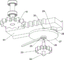
Fig. 1 is a schematic perspective view of the present invention.
Fig. 2 is a schematic perspective view of the moving mechanism of the present invention.
Fig. 3 is a schematic perspective view of the pushing mechanism of the present invention.
FIG. 4 is a schematic view of a first partial body structure according to the present invention.
FIG. 5 is a schematic view of a second partial body structure according to the present invention.
Fig. 6 is a perspective view of a third embodiment of the present invention.
Fig. 7 is a perspective view of a fourth embodiment of the present invention.
FIG. 8 is a schematic view of a fifth partial body structure according to the present invention.
Wherein the figures include the following reference numerals: 1. a housing, 2, a support column, 3, a cutting motor, 4, a moving mechanism, 41, a fixed block, 42, a first slide rail, 43, a first slider, 44, a baffle, 45, a placing plate, 46, a first connecting block, 47, a first movable plate, 48, a second movable plate, 49, a first bearing seat, 410, a rotating rod, 5, a pushing mechanism, 51, a second bearing seat, 52, a first rotating shaft, 53, a first circular gear, 54, a third bearing seat, 55, a second rotating shaft, 56, a bevel gear, 57, a second circular gear, 58, a servo motor, 59, a belt transmission device, 510, a first connecting rod, 511, a sliding plate, 512, a first rack, 513, a missing gear, 514, a third circular gear, 515, an N-shaped block, 516, a first connecting plate, 5161, a second connecting plate, 517, a third movable plate, 518, a third rotating shaft, 519, a fourth circular gear, 520, a second connecting rod, 521, and a first rotating block, 522. the arc-shaped groove, 523, a third connecting rod, 524, a fixing rod, 525, a deflector rod, 6, a mounting plate, 7, a first fixing plate, 8, a protective plate, 81, a cover, 9, a second slide rail, 91, a second rack, 10, a fifth circular gear, 11, a support plate, 12, a sixth circular gear, 13, a slide rod, 14, a clip-shaped groove plate, 15, a seventh circular gear, 16, a third slide rail, 17, a second slider, 18, a second fixing plate, 19, a support block, 20, a second rotating block, 21, a second connecting block, 22, an inserting rod, 23, an eighth circular gear, 24, a ninth circular gear, 25, a fourth connecting rod, 26, a guide sleeve, 27, a disc, 28, a fifth connecting rod, 29, a third rotating block, 30 and a sixth connecting rod.
Detailed Description
In order to make the objects, technical solutions and advantages of the present invention more apparent, the present invention will be described in further detail with reference to the accompanying drawings in conjunction with the following detailed description. It should be understood that the description is intended to be exemplary only, and is not intended to limit the scope of the present invention. Moreover, in the following description, descriptions of well-known structures and techniques are omitted so as to not unnecessarily obscure the concepts of the present invention.
Example 1
The utility model provides a piece equidistance automatic cutout machine for wood working, as shown in fig. 1-5, including casing 1, support column 2, cutting motor 3, moving mechanism 4 and pushing mechanism 5, bottom left side fixedly connected with support column 2 in casing 1, cutting motor 3 is installed at support column 2 top, is equipped with moving mechanism 4 between the upper portion of casing 1 left side, and the right side of casing 1 is equipped with pushing mechanism 5.
When people need to use the machine, people firstly place the wood blocks on the moving mechanism 4, then start the cutting motor 3 and the pushing mechanism 5, then people can move the moving mechanism 4 part back and forth, the moving mechanism 4 part drives the wood block to move back and forth, when the wood block moves forwards to be contacted with the cutting motor 3, the cutting motor 3 cuts the wood block, people to be cut can move the moving mechanism 4 backwards, then the wood block is driven to move backwards, when the moving mechanism 4 part moves backwards and resets, the pushing mechanism 5 part pushes the wood block to move a distance leftwards, then, when the part of the pushing mechanism 5 is far away from the wood block, people can pull the part of the moving mechanism 4 forward again to cut the wood block, so constantly repeat, just can cut the billet fast, when people need not use this machine, close cutting motor 3 and pushing mechanism 5 can.
The moving mechanism 4 comprises a fixed block 41, a first slide rail 42, a first slide block 43, a baffle 44, a placing plate 45, a first connecting block 46, a first movable plate 47, a second movable plate 48, a first bearing seat 49 and a rotating rod 410, the fixed block 41 is fixedly connected to the upper portion of the left front side of the casing 1, the first slide rail 42 is symmetrically arranged between the fixed block 41 and the casing 1, the first slide rail 42 is provided with the first slide block 43 in a sliding manner, the baffle 44 is arranged between the first slide blocks 43, the placing plate 45 is arranged at the rear side of the baffle 44, the first connecting block 46 is arranged at the front side of the baffle 44, another first connecting block 46 is arranged between the bottom of the placing plate 45 and the bottom of the baffle 44, the first movable plate 47 is rotatably arranged between the two first connecting blocks 46, the second movable plate 48 is rotatably arranged at the tail end of the first movable plate 47, the first bearing seats 49 are symmetrically arranged at the rear side of the fixed block 41, the rotating rod 410, the end of the second movable plate 48 is connected to the rotating rod 410.
When people need to cut the wood blocks, people can use the machine, firstly people place the wood blocks on the placing plate 45, then people can start the cutting motor 3 and the pushing mechanism 5, and pull the first movable plate 47 to move forwards, the first movable plate 47 drives the baffle 44, the placing plate 45 and the wood blocks to move forwards through the first connecting block 46, meanwhile, the first movable plate 47 drives the second movable plate 48 to rotate forwards, when the wood blocks move forwards and are in contact with the cutting motor 3, the cutting motor 3 cuts the wood blocks to be cut, people can push the first movable plate 47 to move backwards, further drive the placing plate 45 and the wood blocks to move backwards, when the placing plate 45 is reset, the pushing mechanism 5 part pushes the wood blocks to the left for a certain distance, thus people can efficiently cut the wood blocks by continuously repeating the steps, when people do not need to use the machine, the cutting motor 3 and the pushing mechanism 5 are closed.
The pushing mechanism 5 comprises a second bearing seat 51, a first rotating shaft 52, a first circular gear 53, a third bearing seat 54, a second rotating shaft 55, a bevel gear 56, a second circular gear 57, a servo motor 58, a belt conveyer 59, a first connecting rod 510, a sliding plate 511, a first rack 512, a gear-lacking wheel 513, a third circular gear 514, an N-shaped block 515, a first connecting plate 516, a second connecting plate 5161, a third movable plate 517, a third rotating shaft 518, a fourth circular gear 519, a second connecting rod 520, a first rotating block 521, a third connecting rod 523, a fixing rod 524 and a deflector rod 525, wherein 4 second bearing seats 51 are fixedly connected to the right rectangular array of the bottom in the housing 1, the first rotating shaft 52 is rotatably arranged on the upper parts of the second bearing seats 51, the first rotating shaft 53 is arranged on one opposite end of the first rotating shaft 52, the third bearing seats 54 are symmetrically arranged on the right front side of the inner wall of the housing 1, the third bearing seats 54 are rotatably arranged on the right front side of the, the top of the second rotating shaft 55 is provided with a bevel gear 56, the front ends of the two first rotating shafts 52 on the front side are provided with bevel gears 56, the two adjacent bevel gears 56 are engaged, the lower part of the second rotating shaft 55 is provided with a second round gear 57, the middle of the front side of the bottom in the shell 1 is provided with a servo motor 58, a belt transmission device 59 is connected between the servo motor 58 and the second rotating shaft 55 on the left side, a first connecting rod 510 is symmetrically arranged between the front side and the rear side of the upper part on the right side in the shell 1, the first connecting rod 510 is positioned above a third bearing seat 54, a sliding plate 511 is arranged between the first connecting rods 510 in a sliding manner, the bottom of the sliding plate 511 is provided with a first rack 512, the rear end of the first rotating shaft 52 on the right rear side is provided with a missing gear 513, the missing gear 513 is engaged with the first rack 512, the rear end of the first rotating shaft 52 on the left rear side is provided with a third round, the N-shaped block 515 is positioned between the second bearing seats 51, the N-shaped block 515 is rotatably provided with a first connecting plate 516, the left end and the right end of the first connecting plate 516 are rotatably provided with third movable plates 517, the middle parts of the left third movable plates 517 and the right third movable plates 517 are rotatably provided with second connecting plates 5161, the upper parts of the third movable plates 517 are rotatably provided with third rotating shafts 518, the front end and the rear end of each third rotating shaft 518 are provided with fourth circular gears 519, the fourth circular gears 519 are respectively engaged with the first circular gears 53, the rear part of the right side of the shell 1 is provided with a second connecting rod 520, the second connecting rod 520 is rotatably provided with a first rotating block 521, the first rotating block 521 is positioned at the rear side of the shell 1, the rear part of the right side of the shell 1 is provided with 2 arc-shaped grooves 522, a third connecting rod 523 is arranged between the lower part of the first rotating block 521 and the lower part of the third movable plate, the fixing rod 524 slides in the arc-shaped slot 522 on the upper side, and the top of the first rotating block 521 is provided with a shift lever 525.
When people need to push the wood block to the left, the deflector rod 525 can be pushed to the left, the deflector rod 525 drives the fixed rod 524 to move to the left along the upper arc-shaped groove 522 through the first rotating block 521, the third connecting rod 523 moves to the right along the lower arc-shaped groove 522, the third connecting rod 523 drives the left third movable plate 517 to rotate to the left, the left third movable plate 517 drives the right third movable plate 517 to rotate to the left through the second connecting plate 5161, and then drives the right third rotating shaft 518 and the fourth circular gear 519 to move to the left, so that the right fourth circular gear 519 is meshed with the right first circular gear 53, then people can start the servo motor 58 to rotate counterclockwise, the servo motor 58 drives the left second rotating shaft 55 and the left second circular gear 57 to rotate counterclockwise through the belt conveying device 59, the left second rotating shaft 55 drives the left front first rotating shaft 52 and the left first circular gear 53 to rotate clockwise through the left bevel gear 56, meanwhile, the second round gear 57 on the left side drives the second round gear 57 and the second rotating shaft 55 on the right side to rotate clockwise, the second rotating shaft 55 on the right side drives the first rotating shaft 52 and the first round gear 53 on the right front side to rotate counterclockwise through the bevel gear 56 on the right side, the first round gear 53 on the right front side drives the first round gear 53 on the right rear side to rotate counterclockwise through the third rotating shaft 518 and the fourth round gear 519 on the right side, the first round gear 53 on the right rear side drives the missing gear 513 to rotate counterclockwise through the first rotating shaft 52 on the right rear side, when the missing gear 513 has a tooth part in contact with the first rack 512, the placing plate 45 and the wood block are reset, the missing gear 513 drives the first rack 512 and the sliding plate 511 to move leftward, thereby pushing the wood block to move a distance leftward, then when the tooth part of the missing gear 513 rotates away from the first rack 512, the left end of the sliding plate 511 stays on the placing plate 45, and when the placing plate 45 moves forward, the placing plate 45 drives the sliding plate 511 and the first rack 512 to move forward, when the wood block is cut, the placing plate 45 drives the sliding plate 511 and the first rack 512 to move backward, after the sliding plate 511 and the first rack 512 move backward and reset, the toothed part of the gear 513 contacts with the first rack 512 again, and then pushes the wood block to move leftward again, so that the wood block can be pushed intermittently to move leftward, when the wood block is cut, people push the shifting rod 525 rightward to reset, and then drive the third movable plate 517 to rotate rightward and reset, so that the left fourth circular gear 519 is meshed with the left first circular gear 53, the right fourth circular gear 519 is separated from the right first circular gear 53, the left first circular gear 53 drives the left rear first circular gear 53 to rotate clockwise through the left third rotating shaft 518 and the fourth circular gear 519, and the left rear first circular gear 53 drives the third circular gear to rotate clockwise through the left rear first rotating shaft 52, at this moment, the gear 513 is not rotated, so the third circular gear 514 drives the sliding plate 511 to move rightwards to reset through the first rack 512, after the sliding plate 511 is reset, people can place the next wood block to be cut on the placing plate 45, and the steps are repeated, so that the working efficiency of people can be improved, and when people do not need to use the machine, the servo motor 58 is turned off.
Example 2
On the basis of embodiment 1, as shown in fig. 5 to 8, the portable electronic device further comprises a mounting plate 6, a first fixing plate 7, a protection plate 8 and a cover 81, wherein the mounting plate 6 is fixedly connected to the top of the left side of the housing 1, the first fixing plate 7 is arranged on the right side of the mounting plate 6, the protection plate 8 is arranged on the mounting plate 6 in a rotating manner, the protection plate 8 is matched with the first fixing plate 7, and the cover 81 is arranged on the top of the right side of the housing 1.
When people need use this device, just can rotate guard plate 8 right, make guard plate 8 and first fixed plate 7 contact, and then prevent the contact of staff and cutting motor 3, treat that cutting motor 3 cuts the billet, the billet after the cutting falls on mounting panel 6, and the people of just so being convenient for collect, and wherein, lid 81 can block the part of its below, and then improves the security of this machine.
The device also comprises a second slide rail 9, a second rack 91, a fifth circular gear 10, a support plate 11, a sixth circular gear 12, a slide rod 13, a clip-shaped groove plate 14, a seventh circular gear 15, a third slide rail 16, a second slider 17, a second fixing plate 18, a support block 19, a second rotating block 20, a second connecting block 21, an inserted bar 22, an eighth circular gear 23, a ninth circular gear 24, a fourth connecting rod 25, a guide sleeve 26, a disc 27, a fifth connecting rod 28, a third rotating block 29 and a sixth connecting rod 30, wherein the left front side of the bottom in the shell 1 is fixedly connected with the second slide rail 9, the upper part of the second slide rail 9 is provided with the second rack 91 in a sliding manner, the lower end of the rotating rod 410 is provided with the fifth circular gear 10, the fifth circular gear 10 is meshed with the second rack 91, the rear side of the bottom of the shell 1 is provided with the support plate 11, the right side of the upper part of the support plate 11 is rotatably provided with the sixth circular gear 12, the sixth circular gear, a clip-shaped groove plate 14 is arranged on the sliding rod 13 in a sliding manner, a seventh circular gear 15 is rotatably arranged on the left side of the upper part of the supporting plate 11, the seventh circular gear 15 is meshed with the sixth circular gear 12, a third sliding rail 16 is arranged in the middle of the bottom in the shell 1, a second sliding block 17 is slidably arranged on the third sliding rail 16, a second fixing plate 18 is arranged on the second sliding block 17, a supporting block 19 is arranged at the rear end of the second fixing plate 18, a second rotating block 20 is arranged on the seventh circular gear 15, a second connecting block 21 is rotatably arranged on the second rotating block 20, the second connecting block 21 is rotatably connected with the supporting block 19, an inserting rod 22 is arranged at the front end of the second fixing plate 18, an eighth circular gear 23 is arranged on the inserting rod 22, the eighth circular gear 23 is positioned on the inner side of the second fixing plate 18, a ninth circular gear 24 is arranged on an output shaft of the servo motor 58, the ninth circular gear 24 is meshed with the eighth circular gear, a guide sleeve 26 is rotatably arranged on the fourth connecting rod 25, the inserted link 22 is matched with the guide sleeve 26, a disc 27 is arranged on the guide sleeve 26, a fifth connecting rod 28 is arranged at the eccentric position of the disc 27, a third rotating block 29 is rotatably arranged on the fifth connecting rod 28, a sixth connecting rod 30 is rotatably arranged on the third rotating block 29, and the sixth connecting rod 30 is connected with the second rack 91.
When a person rotates the driving lever 525 to the left, the first rotating block 521 drives the sixth circular gear 12 to rotate counterclockwise through the sliding rod 13, the sixth circular gear 12 drives the seventh circular gear 15 to rotate clockwise, the seventh circular gear 15 drives the second connecting block 21 to move upward through the second rotating block 20, the second connecting block 21 drives the second fixing plate 18 to move upward through the supporting block 19, since the servo motor 58 is not started at this time, the second fixing plate 18 drives the eighth circular gear 23 to move upward to be engaged with the ninth circular gear 24, and simultaneously the second fixing plate 18 drives the inserting rod 22 to move upward, so that the inserting rod 22 is inserted into the guide sleeve 26, when the person starts the servo motor 58, the output shaft of the servo motor 58 drives the ninth circular gear 24 to rotate, the ninth circular gear 24 drives the eighth circular gear 23 to rotate, the eighth circular gear 23 drives the circular disc 27 to rotate through the inserting rod 22 and the guide sleeve 26, and the circular disc 27 further drives the third rotating block 29 to rotate through the fifth connecting rod 28, the third rotating block 29 drives the second rack 91 to slide left and right through the sixth connecting rod 30, when the second rack 91 slides left and contacts with the fifth circular gear 10, the fifth circular gear 10 drives the second movable plate 48 to rotate forward through the rotating rod 410, and further drives the placing plate 45 and the wood block to move forward, so that the cutting motor 3 cuts the wood block, when the sixth connecting rod 30 drives the second rack 91 to slide right, the fifth circular gear 10 drives the second movable plate 48 to move backward through the rotating rod 410, and further drives the placing plate 45 and the wood block to move backward and reset, so that the first movable plate 47 does not need to be manually pushed by people, and further provides convenience for people, and when the shifting rod 525 moves right, the eighth circular gear 23 moves downward and resets.
The above description is only for the specific embodiments of the present invention, but the scope of the present invention is not limited thereto, and any person skilled in the art can easily conceive of the changes or substitutions within the technical scope of the present invention, and all the changes or substitutions should be covered within the scope of the present invention. Therefore, the protection scope of the present invention shall be subject to the protection scope of the claims.
Claims (5)
1. A block equidistant automatic cutting machine for wood processing is characterized by comprising:
the device comprises a shell (1), wherein a support column (2) is arranged on the shell (1);
the cutting motor (3) is arranged at the top of the supporting column (2);
the moving mechanism (4) is arranged between the upper parts of the shells (1);
the pushing mechanism (5) is arranged on the shell (1).
2. An equidistant automatic cutting machine of wood pieces for wood working according to claim 1 characterized in that the moving mechanism (4) comprises:
the fixing block (41) is arranged on the shell (1);
the first sliding rails (42) are symmetrically arranged between the fixed block (41) and the shell (1);
the first sliding blocks (43) are arranged on the first sliding rails (42) in a sliding manner;
the baffle plates (44) are arranged between the first sliding blocks (43);
a placing plate (45), wherein the baffle (44) is provided with the placing plate (45);
the side, far away from the placing plate (45), of the baffle plate (44) is provided with a first connecting block (46), and another first connecting block (46) is arranged between the bottom of the placing plate (45) and the bottom of the baffle plate (44);
a first movable plate (47), wherein the first movable plate (47) is rotatably arranged between the two first connecting blocks (46);
a second movable plate (48), wherein the end of the first movable plate (47) is rotatably provided with the second movable plate (48);
the side, provided with the first sliding rail (42), of the fixed block (41) is symmetrically provided with the first bearing seats (49);
the rotating rod (410) is rotatably arranged on the first bearing seat (49), and the tail end of the second movable plate (48) is connected with the rotating rod (410).
3. An equidistant automatic cutting machine of wood pieces for wood working according to claim 2 characterized in that the pushing mechanism (5) comprises:
the second bearing seats (51), a plurality of second bearing seats (51) are uniformly arranged on the shell (1);
the upper parts of the first rotating shaft (52) and the second bearing block (51) are respectively and rotatably provided with the first rotating shaft (52);
one end of the first rotating shaft (52) opposite to the first circular gear (53) is provided with the first circular gear (53);
the third bearing seat (54) is symmetrically arranged on the inner side of the shell (1);
the second rotating shaft (55) and the third bearing seat (54) are respectively and rotatably provided with the second rotating shaft (55);
the top of each second rotating shaft (55) is provided with a bevel gear (56), each first rotating shaft (52) close to each third bearing seat (54) is provided with a bevel gear (56), and the two adjacent bevel gears (56) are meshed;
the second round gears (57) are arranged on the second rotating shafts (55);
the servo motor (58) is arranged on one side, close to the third bearing seat (54), of the bottom in the shell (1);
the belt conveying device (59) is connected between the servo motor (58) and the adjacent second rotating shaft (55);
the upper part of the shell (1) is symmetrically provided with the first connecting rod (510);
the sliding plate (511) is arranged between the first connecting rods (510) in a sliding way;
the bottom of the sliding plate (511) is provided with a first rack (512);
a gear lack (513) is arranged on one first rotating shaft (52) on one side of the gear lack (513), and the gear lack (513) is meshed with the first rack (512);
a third round gear (514) is arranged on the other first rotating shaft (52) on one side, and the third round gear (514) is meshed with the first rack (512);
the N-shaped block (515) is arranged on the shell (1) between the second bearing seats (51);
the first connecting plate (516) is rotatably arranged on the N-shaped block (515);
the third movable plates (517) are rotatably arranged at two ends of the first connecting plate (516);
the second connecting plate (5161) is rotatably arranged between the third movable plates (517);
the upper parts of the third rotating shafts (518) and the third movable plates (517) are respectively and rotatably provided with the third rotating shafts (518);
the two ends of the third rotating shaft (518) are provided with fourth circular gears (519), and the fourth circular gears (519) are meshed with the first circular gear (53);
the second connecting rod (520), the shell (1) is provided with the second connecting rod (520);
the first rotating block (521) is rotationally arranged on the second connecting rod (520), the first rotating block (521) is positioned on the outer side of the shell (1), and a plurality of arc-shaped grooves (522) are formed in one side, close to the second connecting rod (520), of the shell (1);
a third connecting rod (523), wherein the third connecting rod (523) is arranged between the lower part of the first rotating block (521) and the lower part of the third movable plate (517) on one side, and the third connecting rod (523) slides in the close arc-shaped groove (522);
the fixing rod (524) is arranged at the upper part of the first rotating block (521), and the fixing rod (524) slides in the similar arc-shaped groove (522);
the top of the first rotating block (521) is provided with a deflector rod (525).
4. The equidistant automatic cutting machine of wood pieces for wood working according to claim 3, characterized by further comprising:
the top of one side of the shell (1) close to the cutting motor (3) is provided with the mounting plate (6);
the first fixing plate (7) is arranged on one side, close to the cutting motor (3), of the mounting plate (6);
the protective plate (8) is rotatably arranged on the mounting plate (6), and the protective plate (8) is matched with the first fixing plate (7);
a cover (81), and the top of the other side of the shell (1) is provided with the cover (81).
5. The equidistant automatic cutting machine of wood pieces for wood working according to claim 4, characterized by further comprising:
a second slide rail (9), wherein the shell (1) below the moving mechanism (4) is provided with the second slide rail (9);
the second rack (91) is arranged on the second sliding rail (9) in a sliding manner;
the lower end of the rotating rod (410) is provided with a fifth circular gear (10), and the fifth circular gear (10) is meshed with the second rack (91);
the supporting plate (11) is arranged on one side, close to the first rotating block (521), of the shell (1);
a sixth circular gear (12), wherein the support plate (11) is rotatably provided with the sixth circular gear (12);
the sliding rod (13) is arranged at the eccentric position of the sixth circular gear (12);
the slide rod (13) is provided with a clip-shaped groove plate (14) in a sliding way;
the supporting plate (11) is rotatably provided with a seventh circular gear (15), and the seventh circular gear (15) is meshed with the sixth circular gear (12);
a third slide rail (16), wherein the middle of the bottom in the shell (1) is provided with the third slide rail (16);
the second sliding block (17) is arranged on the third sliding rail (16) in a sliding manner;
a second fixed plate (18), and a second fixed plate (18) is arranged on the second sliding block (17);
one end of the second fixing plate (18) close to the seventh circular gear (15) is provided with a supporting block (19);
the seventh circular gear (15) is provided with a second rotating block (20);
the second connecting block (21) is rotationally arranged on the second rotating block (20), and the second connecting block (21) is connected with the supporting block (19);
the other end of the second fixing plate (18) is provided with an inserting rod (22);
the eighth circular gear (23) is arranged on the inserted rod (22), and the eighth circular gear (23) is positioned on the inner side of the second fixing plate (18);
a ninth circular gear (24), wherein the output shaft of the servo motor (58) is provided with the ninth circular gear (24), and the ninth circular gear (24) is meshed with the eighth circular gear (23);
a fourth connecting rod (25) is arranged on the second slide rail (9);
the guide sleeve (26) is rotatably arranged on the fourth connecting rod (25), and the inserted rod (22) is matched with the guide sleeve (26);
the disc (27) is arranged on the guide sleeve (26);
a fifth connecting rod (28), wherein the fifth connecting rod (28) is arranged at the eccentric position of the disc (27);
a third rotating block (29), and the fifth connecting rod (28) rotates the third rotating block (29) upwards;
and the sixth connecting rod (30) is rotationally arranged on the third rotating block (29), and the sixth connecting rod (30) is connected with the second rack (91).
Priority Applications (1)
| Application Number | Priority Date | Filing Date | Title |
|---|---|---|---|
| CN202010772024.4A CN112060206B (en) | 2020-08-04 | 2020-08-04 | Automatic wood block equidistant cutting machine for wood processing |
Applications Claiming Priority (1)
| Application Number | Priority Date | Filing Date | Title |
|---|---|---|---|
| CN202010772024.4A CN112060206B (en) | 2020-08-04 | 2020-08-04 | Automatic wood block equidistant cutting machine for wood processing |
Publications (2)
| Publication Number | Publication Date |
|---|---|
| CN112060206A true CN112060206A (en) | 2020-12-11 |
| CN112060206B CN112060206B (en) | 2022-08-19 |
Family
ID=73656875
Family Applications (1)
| Application Number | Title | Priority Date | Filing Date |
|---|---|---|---|
| CN202010772024.4A Active CN112060206B (en) | 2020-08-04 | 2020-08-04 | Automatic wood block equidistant cutting machine for wood processing |
Country Status (1)
| Country | Link |
|---|---|
| CN (1) | CN112060206B (en) |
Cited By (6)
| Publication number | Priority date | Publication date | Assignee | Title |
|---|---|---|---|---|
| CN112776090A (en) * | 2021-01-05 | 2021-05-11 | 泰和县祥峰木艺制品有限公司 | Cutting and forming equipment for wooden stair treads |
| CN112873423A (en) * | 2021-01-15 | 2021-06-01 | 罗仕兵 | A cut cake device for wooden rod |
| CN112917601A (en) * | 2021-02-20 | 2021-06-08 | 龚俊杰 | Furniture production is with wooden bench foot cutting device |
| CN112917588A (en) * | 2021-03-18 | 2021-06-08 | 谭忠山 | Drilling and cutting equipment for high-end equipment |
| CN112975126A (en) * | 2021-03-02 | 2021-06-18 | 赣州市恒邦金属制品有限公司 | Laser cutting device convenient to it is clean |
| CN113771145A (en) * | 2021-08-16 | 2021-12-10 | 刘会妹 | Equidistant cutting device is used in log processing |
Citations (7)
| Publication number | Priority date | Publication date | Assignee | Title |
|---|---|---|---|---|
| US20020092397A1 (en) * | 2001-01-17 | 2002-07-18 | Tony Liu | Auxiliary workpiece-supporting frame assembly for a table saw |
| CN107053344A (en) * | 2017-04-28 | 2017-08-18 | 中源家居股份有限公司 | A kind of timber automatic gas cutting machine |
| CN207548937U (en) * | 2017-12-15 | 2018-06-29 | 李向忠 | Wooden unit blanking machine |
| CN208005852U (en) * | 2018-03-23 | 2018-10-26 | 重庆青草边家具制造有限公司 | A kind of plate cutting device |
| CN109200912A (en) * | 2018-11-16 | 2019-01-15 | 于秀凤 | A kind of chemical experiment test tube centrifugation rocking equipment |
| CN209466335U (en) * | 2018-07-13 | 2019-10-08 | 严昊昕 | A kind of stacked sawing machine |
| CN210361676U (en) * | 2019-05-06 | 2020-04-21 | 阜阳大可新材料股份有限公司 | Production fibreboard is with saw cutting device |
-
2020
- 2020-08-04 CN CN202010772024.4A patent/CN112060206B/en active Active
Patent Citations (7)
| Publication number | Priority date | Publication date | Assignee | Title |
|---|---|---|---|---|
| US20020092397A1 (en) * | 2001-01-17 | 2002-07-18 | Tony Liu | Auxiliary workpiece-supporting frame assembly for a table saw |
| CN107053344A (en) * | 2017-04-28 | 2017-08-18 | 中源家居股份有限公司 | A kind of timber automatic gas cutting machine |
| CN207548937U (en) * | 2017-12-15 | 2018-06-29 | 李向忠 | Wooden unit blanking machine |
| CN208005852U (en) * | 2018-03-23 | 2018-10-26 | 重庆青草边家具制造有限公司 | A kind of plate cutting device |
| CN209466335U (en) * | 2018-07-13 | 2019-10-08 | 严昊昕 | A kind of stacked sawing machine |
| CN109200912A (en) * | 2018-11-16 | 2019-01-15 | 于秀凤 | A kind of chemical experiment test tube centrifugation rocking equipment |
| CN210361676U (en) * | 2019-05-06 | 2020-04-21 | 阜阳大可新材料股份有限公司 | Production fibreboard is with saw cutting device |
Cited By (6)
| Publication number | Priority date | Publication date | Assignee | Title |
|---|---|---|---|---|
| CN112776090A (en) * | 2021-01-05 | 2021-05-11 | 泰和县祥峰木艺制品有限公司 | Cutting and forming equipment for wooden stair treads |
| CN112873423A (en) * | 2021-01-15 | 2021-06-01 | 罗仕兵 | A cut cake device for wooden rod |
| CN112917601A (en) * | 2021-02-20 | 2021-06-08 | 龚俊杰 | Furniture production is with wooden bench foot cutting device |
| CN112975126A (en) * | 2021-03-02 | 2021-06-18 | 赣州市恒邦金属制品有限公司 | Laser cutting device convenient to it is clean |
| CN112917588A (en) * | 2021-03-18 | 2021-06-08 | 谭忠山 | Drilling and cutting equipment for high-end equipment |
| CN113771145A (en) * | 2021-08-16 | 2021-12-10 | 刘会妹 | Equidistant cutting device is used in log processing |
Also Published As
| Publication number | Publication date |
|---|---|
| CN112060206B (en) | 2022-08-19 |
Similar Documents
| Publication | Publication Date | Title |
|---|---|---|
| CN112060206B (en) | Automatic wood block equidistant cutting machine for wood processing | |
| CN111975877B (en) | Plank slitting equipment | |
| CN112454537A (en) | Automatic material sawing equipment that pushes away of industrial stuff | |
| CN112518905B (en) | Rectangular wood board slotting device for furniture decoration | |
| CN112297116B (en) | Slicer is used in sesame sugar production | |
| CN112025877B (en) | Washboard manufacture equipment | |
| CN112976168A (en) | Furniture production is with plank length ration cutting device | |
| CN112157464A (en) | Equipment for cutting stainless steel gasket | |
| CN111644500A (en) | Stamping equipment for sheet metal parts | |
| CN112847489B (en) | Automatic board device of cutting is erected to PS board | |
| CN113043483B (en) | Equidistant cutting machine of corridor post preparation for ancient building corridor bridge | |
| CN215282054U (en) | Carbon-point filter core cutting device that environmental protection was used | |
| CN212163848U (en) | Electronic circuit board processing device with dust collection function | |
| CN214293543U (en) | Cutting device is used in timber processing | |
| CN112476653A (en) | Square stick cuts into circle device | |
| CN219131118U (en) | Automatic cutting slag remover for table top | |
| CN103895049A (en) | Automatic-feeding fresh meat slicing machine | |
| CN112772934A (en) | Gourd pulp removing machine | |
| CN112171802B (en) | Mark opening equipment for washboard | |
| CN213765028U (en) | Drilling feeder | |
| CN114683359B (en) | Wood-based plate cutting device | |
| CN112809784A (en) | Industrial potato processing blocking device | |
| CN112643803A (en) | Promotion formula timber perforating device | |
| CN111977279A (en) | Even conveying equipment of mud that cutter earthing sword was used of burning | |
| CN213794516U (en) | Cutting device for machining rolling bearing |
Legal Events
| Date | Code | Title | Description |
|---|---|---|---|
| PB01 | Publication | ||
| PB01 | Publication | ||
| SE01 | Entry into force of request for substantive examination | ||
| SE01 | Entry into force of request for substantive examination | ||
| TA01 | Transfer of patent application right |
Effective date of registration: 20220728 Address after: 537000 longwuling (zhouhanquan house) near BAISHILING, shanbian village, Xintang Town, Gangnan District, Guigang City, Guangxi Zhuang Autonomous Region Applicant after: Guigang Linwei Wood Industry Co.,Ltd. Address before: 518002 room 115, 13 / F, West building, Department Store Plaza, No. 3020, Shennan East Road, Luohu District, Shenzhen, Guangdong Province Applicant before: Fan Jianwen |
|
| TA01 | Transfer of patent application right | ||
| GR01 | Patent grant | ||
| GR01 | Patent grant |