The following describes a kind of variable speed system.In the following description, many details have been proposed, set-point for example, wattage or the like.But it will be understood by those of skill in the art that the present invention can be implemented without these specific details.In addition, the construction and device of knowing represents with Block Diagram, and do not provide details, so that the present invention is described more concisely.
The invention provides a kind of variable speed system, in one embodiment, described variable speed system comprises the wind wheel generator with certain power/torque capacity, and it links to each other with electrical network and to mains supply.In one embodiment, generator of the present invention comprises coil wound rotor influence generator (WRIG or double-fed generator (DFG)) and utilizes pitching blade to regulate and also can carry out the variable speed operation so that can both reach the rotor of best power output under all wind speed.
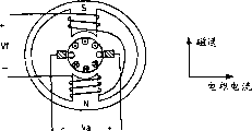
The ability that influence generator produces power is equivalent to it produces torque under certain rotating speed ability.When applying torque along the direction with its switched in opposite on generator amature, the mechanical energy of rotor just is converted into electric energy.In influence generator, torque is to be produced by the interaction between electric current and the magnetic flux, and as shown in Figure 3, or rather, torque is the cross product of electric current and magnetic flux.In order to produce maximum torque under given magnetic flux, the direction of rotor current vector and the direction of magnetic flux are accurately kept 90 degree.In direct current motor, this vertical relation between magnetic flux and the armature supply is finished by commutator.
Fig. 4 represents the structure of the direct current motor in wire-wound magnetic field.Because armature winding and magnetic field winding separate,, direct current motor controls with the magnetic field winding current that is used for required Magnetic flux density by adjusting so can reaching required torque output by the adjusting armature supply.
The principle that produces torque in influence generator is identical with direct current motor.Both main distinctions are that in direct current motor, the direction of magnetic flux and armature supply is fixed, and in influence generator, these two vectors rotate with constant speed.
Field orientation control (FOC) be a kind of be used to discern magnetic flux vector and correspondingly controlling torque produce a kind of algorithm of electric current.
Fig. 5 represents the flow direction when the staor winding that has only the A phase is energized.In system shown in Figure 2, encourage each phase of stator in order by three-phase voltage source, thereby produce the rotating magnetic flux vector.
Notice that magnetic flux and three phase circuit are two dimension (2D) vectors (promptly having amplitude and phase angle), and be that magnetic flux vector (Ψ) is provided by following formula with the relation of stator current vector (Is) at 0 o'clock at rotor current:
(1) Ψ=Ls*Is
Wherein Ls is a stator inductance.When the rotor winding was not energized, class generator was similar to a reactor, that is, and and stator current hysteresis stator voltage 90 degree, or rather,
(2) Vs=dΨ/dt=LsdIs/dt
Wherein Vs represents stator voltage.
A critical elements is the magnetic flux model in FOC.The magnetic flux model is used to discern magnetic flux vector.Formula (1) is the simplest form of the magnetic flux model of WRIC, and the expression magnetic flux vector can be discerned simply by the product of getting stator current measured value (Is) and stator inductance (Ls).By using this magnetic flux model, can discern magnetic flux vector, thereby make and to produce power by controlling torque.
Carry out though the following description is the wind turbine according to variable wind speed, the present invention can be used for other electric and mechanical system.For example, generator of the present invention can be used for having other system that makes the energy that the axle that links to each other with generator amature rotates, for example water turbine, gas turbine and general prime mover system etc.
In one embodiment, wind turbine of the present invention comprises the rotor with 3 blades, and comprises having the control of full span pitching blade, pitch bearing and wheel hub.This wind turbine rotor is known in related domain.Note to use in the present invention any amount of blade and any other turbine structure.Wind turbine rotor links to each other with a whole chain that comprises main shaft.Main shaft links to each other with generator.
System of the present invention also comprises the power inverter between the coil wound rotor that is set at electrical network and double-fed coil wound rotor influence generator.Stator links to each other with electrical network by contactor.Because transducer is arranged in rotor circuit, the part of total specified kilowatt output number of its processing (for example conversion) wind turbine rotor.In one embodiment, total specified output of wind turbine rotor comprises 750KW, and wherein transducer is to percent 25-30 (for example 160KW) of the total specified output of different transform.In one embodiment, generator is a 750KW, the coil wound rotor influence generator of 460V.
In one embodiment, the invention provides a kind of variable speed system, it has the coil wound rotor influence generator, torque controller and proportion integration differentiation (PID) pitching (or speed) controller.Influence generator of the present invention can comprise slip ring type influence generator or not have slip ring type influence generator.Described variable speed system uses has the coil wound rotor influence generator of power converter system, so that guarantee to provide to electrical network the power of constant frequency.Though what note explanation is to be used for electrical network, those skilled in the art is to be understood that the present invention can be used for others, for example independently electric power system.
Generally be used to control the torque of generator as the torque controller of the part of power inverter.In one embodiment, torque controller utilizes the speed controlling generator torque of magnetic flux vector control according to generator by field orientation control (FOC) method.Torque controller is linked into the rated wind speed operate generator from generator.In one embodiment, insert the minimum wind speed refer to generator or wind turbine being designed work, and the minimum windspeed of rated speed when to be wind turbine produce its peak output (for example 750KW).In one embodiment, under above-mentioned rated wind speed, the power invariability that torque controller keeps generator amature to send.
In one embodiment, power controller comprises a look-up table (LUT), and it is according to generator amature speed output power value.Power controller interpolation LUT, it contains the power-velocity curve of coding, so that obtain target output.This power is then divided by the generator amature speed that records, thereby obtains required generator torque by formula T=P/ ω (torque=power/angular velocity).In one embodiment, the output of LUT is target output, uses comparator or difference hardware or software that this power and actual output power are compared, thereby produces the power error indication.Proportional integral (PI) controller produces the indication of responding power error and produces the real output value of adjusting, and passes through hardware or software divider then divided by the generator amature speed of measuring, thereby obtains command torque.Command torque makes specific rotor current vector be added on the rotor, and itself and the magnetic flux vector of discerning interact and produce required generator torque.
Thereby, the present invention also is used to control generator torque, wherein by measuring actual alternator speed, use the spinner velocity visit LUT that measures, thereby acquisition target output, relatively real output and target output produce command torque by adjusting torque calculation, thereby relatively keep predetermined output according to real output and target output.
In one embodiment, use is used for the processing of synchronous this variable speed system, comprising connecting generator unit stator, connect generator amature, increase rotor current magnetization component Ird (component of the generation torque of rotor current) in proportion, and produce the torque of component regulator generator by the magnetic flux of control rotor current Irq.
System of the present invention also comprises a kind of variable pitching and speed regulation subtense angle, and it provides real-time ratio pitch position and wind turbine speed regulation by usage ratio, integration, differential (PID) controller.
The PID controller is carried out pitch regulation according to generator amature speed, and is independent of the torque controller in the power inverter and operates.In one embodiment, the PID controller is a kind of PID controller of closed loop, and it produces pitch rate and carries out pitch regulation when being equal to or greater than rated wind speed.In one embodiment, the PID controller is carried out pitch regulation during less than above-mentioned rated wind speed.In one embodiment, below rated velocity, pitching angle is fixed on the flat-out position of output.
The PID controller is by making the pitching blade control generator amature speed of wind turbine.In one embodiment, difference between the spinner velocity of PID controller response target spinner velocity and measurement (reality) produces output voltage, a nonlinear LUT (in one embodiment, the table 1011 of Figure 10) uses sort controller, thereby respond described output voltage output pitch rate.
Though the present invention is illustrated in conjunction with the PID controller, in an embodiment also can usage ratio integration (PI) controller, proportion differential (PD) controller or proportional controller.Also can use the controller of other hysteresis-leading or leading-hysteresis.In addition,, also can use open-cycle controller, for example have the open-cycle controller of differential term though the present invention is illustrated in conjunction with closed loop controller.Such controller is to know in related domain.
Fig. 6 A explanation is according to an embodiment of system of the present invention.Referring to Fig. 6 A, the generator torque control 603 in the variable speed transducer is connected for receiving the torque 601 and the predetermined peak torque set-point 602 of calculating according to the rpm607 that measures.In one embodiment, calculating torque 601 is based on the function of rpm of the measurement of the generator of checking table/power speed curve 640.The output of table 640 uses divider 641 divided by the rpm607 that measures.
In one embodiment, peak torque 602 is set to about 5250Nm, and this is selected based on the maximum current that can obtain from the changer system thermal rating.In other words, for specific wind turbine rotor design, this is selected based on the torque-speed characteristic that calculates.In one embodiment, this selects the excitatory amount based on 290amp.
Respond these inputs, torque control 603 produces a torque instruction that is used to control generator amature 604.Torque control 603 is also linked to each other is used to receive VAR or power factor instruction 642.
Generator amature 604 is connected for receiving the torque instruction from generator torque control 603, and is connected for providing power by magnetic gap to generator unit stator output 605.Feedback 612 is connected to the input of generator amature 604 from generator unit stator output 605.The output of generator amature 604 is connected to shared electrical network 606.
Generator amature 604 also is connected to the measuring device of the measuring speed 607 (rpm) that is used to produce generator amature 604.In one embodiment, measuring device comprises optical encoder, is used to provide the position and the rotational speed of generator amature 604.
Ratio, integration and differential (PID) controller and pitch rate confinement block 609 are connected for receiving measuring speed 607 and service speed set-point 608.The service speed set-point can be according to the identical torque speed characteristic setting that is used for determining the peak torque set-point.In one embodiment, the service speed set-point is based on the torque and the power of maximum.In one embodiment, service speed set-point 608 is 1423rpm.Respond these inputs, PID and pitch rate confinement block 609 produce a voltage output.
Variable elevating control (VPC) 601 is connected for receiving the pitch rate output from PID and pitch rate confinement block 609.VPC610 links to each other with vane rotor 611 and is used for by control the aerodynamics torque of the vane rotor 611 of input by means of the pitching blade effect.PID and pitch rate confinement block 609 produce required pitch rate, and it uses a table to be converted into voltage, will describe in detail as following.Variable voltage output is applied in a Proportional valve in the hydraulic system, and it makes pitching blade by activating the pitching cylinder with variable speed.Thereby variable elevating control is by control aerodynamics torque adjustment rpm.
Comprise that the rpm607 of measurement and PID and pitch rate confinement block 609, VPC610 and the vane rotor 611 of service speed (rpm) set-point 608 form pitching blade system 650, and the remaining part of the system of the rpm607 that measures and Fig. 6 A is the part of power inverter and generator system 651.Notice that in one embodiment the rpm607 of measurement is used by pitching blade system 650 and power inverter/generator system 651 simultaneously.
In the present invention, power inverter is according to predetermined electric power velocity curve control coil wound rotor influence generator.By following the predetermined electric power velocity curve, the variable speed system can be from being linked into the power factor operation wind turbine of rated wind speed (being called the II district herein) with maximum, so as to guaranteeing to realize maximum aerodynamics energy capture.Should be noted that power speed curve is relevant with the torque velocity curve, because P=T ω.
In one embodiment, power speed curve is encoded with the form of power with the look-up table (LUT) of corresponding alternator speed in power inverter.LUT can reside in hardware or the software.For controlling torque, power inverter is measured generator amature speed, interpolation LUT, thus determine target wind turbine output power, and utilization concerns that T=P/ ω uses the required generator torque of generator amature speed calculation.In one embodiment, this torque is wherein used the pulse modulation technology of knowing to produce described vector by producing by means of definite required current phasor.
In one embodiment, because the little deviation between theory and the reality, power inverter of the present invention uses the PI controller of closed loop, wind turbine power output and desired value or required output that it is relatively actual, and torque calculation carried out little adjusting, so that reach and keep required wind turbine output.
The torque controller of power inverter uses field orientation control (FOC) to produce generator torque according to generator amature speed.Use stator current, rotor current and rotor angle as input quantity, the torque controller identification magnetic flux vector of power inverter, and the instruction of sending required rotor current vector, this vector and stator flux vector interact, and produce required generator torque.Switch by the igbt (IGBT) that correctly makes transducer, produce rotor current, wherein use pulsewidth modulation (PWM) the electric current adjustment technology know, for example on January 21st, 1992 disclosed name be called and describe among the patent US5083039 of " wind turbine of variable speed ".In this way, power control system is followed the power/torque-velocity curve of the best aspect aerodynamics.
The value of look-up table of noting containing power/torque-velocity curve is based on the geometrical shape of the air dynamic behaviour and the wind turbine rotor of specific wind turbine rotor.Therefore, the value that is set at described table is different for different wind turbine rotors.
An embodiment of the torque controller of coil wound rotor influence generator and relevant part is shown in Fig. 6 B.Torque can be represented as:
(3)Td=k*Ψ*Irq
Wherein k is a generator parameter.The viewpoint of slave controller be it seems, the form below formula (3) adopts:
(4)Irq=Td/(k*Ψ)
For the given required torque Td from 623 outputs of torque instruction controller, formula (4) provides the size of rotor current.
Referring to Fig. 6 B, torque controller 623 comprises wattmeter 623A, PI controller 623B, divider 623C, switch 629 and can produce the comparator 623D and the 623E of difference and just present damping filter 623F with hardware or software being used to of realizing.Wattmeter 623A is a LUT, and it is connected for receiving alternator speed 607 and the output target power value corresponding to alternator speed 607.The embodiment of wattmeter 623A is shown in following table 1: table 1
| Alternator speed RPM | Electric power (kW) |
| 750 800 850 900 950 1000 1050 1100 1150 1200 1250 1300 1350 1400 1450 1500 1550 1600 | -177 -177 135 167 203 247 287 335 388 450 507 575 647 743 750 750 750 750 |
Target output by comparator 623D relatively, thereby produce poor between target output and the real output.The difference of gained is imported into PI controller 623B, and it regulates power as required.Divider 623C is connected for receiving the power from the adjusting of PI controller 623B and alternator speed 607, and the output order torque.
Command torque can just be presented the torque value of damping filter 623F generation and be adjusted.Damping filter 623F detects the harmonic moving (when resonance) of non-rigid (being obedient to) axle (not shown for the sake of simplicity), described harmonic moving is to be caused by the connection of the coupling between the inertia thing that separates at two, one of them inertia thing is owing to gear-box and generator form, and another is that blade by wind turbine forms.Respond this and detect, damping filter 623F applies a negative torque so that reduce by two relative movement between the inertia thing.In one embodiment, damping filter 623F comprises band-pass filter, and wherein the center of passband is on the resonant frequency of two inertia things and axle.
The command torque of gained is added on the coil wound rotor of influence generator.
Switch 629 responses are braked index signals and are worked, and command torque is converted into maximum constant torque 660, describe in detail as following.
About producing the operation of torque, control the magnetic flux (seeing Fig. 6 D) that a rotor current component Irq flows through Vertical direction.The amplitude of Irq is provided by following formula:
Irq=Td/(k*Ψ)
Wherein k is a generator parameter.Note rotor current Ird, describe in detail below, produce generator magnetic flux and do not produce torque.
Rotor current component blocks 622 is connected for receiving command torque and from the scalar component of the magnetic flux vector of right angled coordinates-polar coordinate transform piece 626, transform block is transformed to polar coordinates to magnetic flux vector from magnetic flux model 621.Respond these inputs, rotor current component blocks 622 produces rotor current torque component Irq.
Magnetic flux model 621 identification magnetic flux vectors.Be the identification magnetic flux vector, power pack piece 621A and 621B obtain stator current vector and rotor current vector.Note because current phasor can be determined by the two-phase of measuring in the three phase circuit, so only need two current probe (not shown).Stator current vector with rotor angle 621B of generator 620 is transfused to frame transform piece 627C.Frame transform piece 627C is transformed to the fixing framework of rotor to stator current.By the output of frame transform piece 627C, determine stator inductance Ls at piece 621D.By the rotor current vector, can obtain inductor rotor Lr at piece 621F.Produce magnetic flux vector by stator inductance Ls and inductor rotor Lr.
In case determine magnetic flux vector, from the rotor current vector output of inverter 624 just by along direction " location " perpendicular to magnetic flux, thereby the generation torque.Because for the rotor part rotor current is specific, so magnetic flux angle and rotor angle are depended in the rotor current instruction.Specifically, the magnetic flux angle is at first transformed to the fixing reference frame of rotor, and in this reference frame, the direction of rotor current instruction is perpendicular to the direction of magnetic flux.This process is shown in Fig. 6 C.
Use rotor current component Irq, the perceptual part of associative transformation piece 626 outputs is at the input end generation current reference of inverter 624.As shown in the figure, inverter 630 links to each other with inverter 624 by dc bus 631, and links to each other with the stator side (line side) of generator 620.
When forcing this rotor current to flow through the rotor winding, just produce required torque Td, and produce power (Td* ω), wherein ω is a spinner velocity.This power is produced with the form of the stator current that flows back to electrical network.Produce the stator current and the stator voltage homophase of this power.
When sending power by generator, above the magnetic flux model that illustrates of formula (1) no longer valid, this is because stator current is made of two components now: magnetic flux produces component and power carrying component.Power carrying component does not produce magnetic flux, because this current component has and produces the identical amplitude of rotor current with torque but direction is opposite.In other words, the magnetic flux sum that is produced by these two current phasors (being that power carrying stator current and torque produce rotor current) is 0.In order to remove power carrying component from the measured value of stator current, rotor current (Ir) is added to above-mentioned formula (1), that is,
Ψ=Ls*Is+Lr*Ir
Wherein Lr is an inductor rotor.Ls and Lr differ a ratio of winding.
Attention is in above-mentioned operation, though power carrying stator current component and stator voltage cophasing, magnetic flux produces component hysteresis stator voltage 90 degree.This magnetic flux produces current component makes the stator power factor be not equal to 1.Because magnetic flux produces electric current lagging voltage 90 degree inherently,, need produce magnetic flux by the rotor winding so will make the power factor of stator side equal 1.
In order to produce magnetic flux, should have the additional components Ird of a rotor current by the rotor winding.This additional components should be along the direction of magnetic flux, shown in Fig. 6 D.
When the magnetic flux of rotor current (Ird) produced the component increase, magnetic flux produces stator current then to be reduced.This be since the amplitude of magnetic flux owing to constant stator voltage is held constant (formula 2).The magnetic flux of rotor current produces component Ird can make the flux of magnetic induction of its generation go out the voltage identical with line voltage by such method control.That is, the size of induced voltage and line voltage is identical with phase place.In this case, the voltage of induction overcomes line voltage, thereby staor winding do not draw stator current, and this is the situation that the system power factor equaled 1 o'clock.
Notice that VAR/ power factor controlling 670 can be included in the system, is used to control the generation of wattless power.(product of stator voltage Vs and stator current vector Is (when not producing torque) is represented the required excitatory wattless power of generator.)
Power inverter is only just worked when being activated.Wind turbine controller starts and forbids power inverter, shown in Fig. 7 piece 705.This wind turbine controller can realize with the combination of hardware, software or hardware and software, for example in based on the computer of system or controller like that.In one embodiment, the present invention uses binary logic voltage signal gating and forbids power inverter, and this paper is called the transducer gating siganl to it.
In one embodiment, when wind turbine controller is in normal mode of operation when (this paper is called automated manner), wind turbine controller makes wind turbine to wind direction deflection, and makes the blade of wind turbine be in the full power position.The full power position is to understand easily for those skilled in the art.Give enough wind-force, blade just begins rotation, thereby alternator speed increases.In case alternator speed reaches predetermined transducer toggle speed, wind turbine controller just sends the transducer actuating signal to power inverter.In one embodiment, Yu Ding transducer toggle speed is 820rpm.
The transducer actuating signal is received in response, begins to carry out the transducer start-up routine.In one embodiment, system begins closed alternating current circuit contactor (in inverter 630), and this makes circuit body (in inverter 630) link to each other with electrical network.A predetermined delay can be so that do not produce transition when contactor is closed.In one embodiment, this predetermined delay is 1.5 seconds.An embodiment of gating program is elaborated in conjunction with Fig. 7 and piece 714,715,716 and 717.
After the contactor closure, the bus precharge circulation takes place, so that guarantee that bus is fully charged, and can regulate instantaneous torque.In this case, regulate DC bus-bar voltage to a predetermined value.In one embodiment, described predetermined value is the 750V VDC.Can use another delay to be used to guarantee bus, thereby correctly regulate by fully precharge.In one embodiment, described delay can be 5 seconds.In one embodiment,, then produce bus overvoltage or undervoltage fault, and send the transducer trouble signal to wind turbine controller if bus is not conditioned.
When alternator speed is equal to or greater than a predetermined speed and has postponed through predetermined bus (after bus is carried out the abundant charging in 5 seconds), stator contactor is closed (piece 714), thereby encourages staor winding and produce the rotational stator magnetic flux.Staor winding only uses voltage excitatory.Because the inductance of staor winding, inrush current is very little, and in one embodiment, has only 75% maximum operating current.In one embodiment, predetermined speed is 900rpm.Can utilize a delay to make stator contactor closed and reduce transition.In one embodiment, described delay was 3 seconds.
When alternator speed reaches or greater than predetermined speed, and when confirming that rotor voltage is lower than a predetermined voltage peak, the rotor contactor is closed (piece 715), thereby the generator matrix is linked to each other with the rotor of coil wound rotor influence generator.In one embodiment, predetermined speed is 1000rpm, and the predetermined voltage peak value is 318V.Can use a delay to make rotor contactor closure.In one embodiment, described delay is 0.5 second.At this moment, the IGBT of rotor-side (in the inverter 624) does not switch.Because rotor-side IGBT does not switch as yet,, do not produce transition or power so there is not electric current to flow through.Because do not have active power (having only wattless power), can not produce torque shock ends.
When rotor-side IGBT conducting, begin to produce power, be produced as this moment and produce the required current phasor (size and position) of required torque.In one embodiment, response produces described current phasor from the instruction of torque controller (for example processor).At first, this torque rises to the value of being stipulated by best power/torque-velocity curve from 0 by certain slope.Rise by certain slope and can eliminate the drift of power or torque, and make wind turbine connecting system smoothly.
Notice that synchronous with traditional " synchronously " process of using of the present invention is different in synchronous or mouse cage induction machine, refer in the present invention, during not the wind turbine connecting system and the impact, transition or the oscillation of power that produce.
In case synchronously, power inverter is just observed above-mentioned power-velocity curve (piece 717), up to being removed by wind turbine controller.
Should be noted that above-mentioned delay about the transducer start-up course can regulate according to the element that uses in the system with in the environmental conditions that the wind wheel pusher side exists.These can be realized by hardware and software.
In one embodiment, the power that is input to wind turbine is provided by wind-force.If wind speed changes, then the input power of wind turbine changes.In order to compensate the change of input power, the invention provides a kind of update method that is used to upgrade generator torque.Because generator torque is determined (instantaneous) by power inverter, so alternator speed increases according to horse-power formula P=T ω.The power inverter alternator speed of sampling continuously, the speed that identifies changes, and discerns new speed, and upgrades the power demand in the look-up table.Power inverter is determined new torque by required power and is calculated the new current phasor be added on the generator amature according to FOC.In one embodiment, every 33 milliseconds or take place once to upgrade to handle, follow power-velocity curve every two cycles of 60Hz circuit with making the wind turbine exactly.Notice that renewal speed can change or can dynamically change during operation.
Below rated wind speed (for example area I I), make blade keep the predetermined electric power capture angle, thereby generator/wind turbine speed of this moment depend on command torque and wind-force input.This guaranteed output-velocity curve is correctly selected.In one embodiment, the predetermined power capture angle is maximum power capture angle (for example 0,1, or 2 degree pitching).The reading of pitching angle changes according to wind speed.
Rated power occurs under the predetermined generator amature speed.In one embodiment, this speed is 1423rpm.Surpass rated wind speed, generator amature speed is controlled by the PID controller, and its response generator amature speed represents to make pitching blade.Notice that described expression can be with multi-form change, comprising but be not limited to a signal or the velocity amplitude of in register, storing.Importantly, PID elevating control device is independent of power inverter and works.If power inverter fault, PID controller then keep the speed (1423rpm in one embodiment) of generator by the bigger blade pitch angle of instruction.Like this, the failsafe operation device of dress in this system has.
For being equal to or greater than the generator speed that produces rated power (for example 1423 or more), power speed curve is such, makes power inverter keep power invariability, thereby not significantly fluctuation.Thereby, the fitful wind more than rated wind speed, it is tending towards increasing wind turbine speed, does not have what influence for generator power, because response of PID controller and regulator generator spinner velocity.But, the response of PID controller is such, and it can control spinner velocity effectively in about 5% scope, thereby the power controlling drift, for the wind speed that is equal to or greater than rating value, can produce almost constant power.
More than rating value, because the maintenance of stator power is constant, when the rotor by the coil wound rotor influence generator produced excessive power, power excursion must be to not influence of line voltage.Between these drift episodes, make torque keep constant by power inverter, rotor current (and stator current) is held constant (torque and electric current are directly proportional).Because rotor current is a constant during fitful wind, the increase of rotor power is because the increase of rotor voltage.But because power inverter between generator amature and electrical network is converted to constant AC wave shape (for example 60Hz, 460V AC wave shape), the influence that line voltage is not increased by this voltage to the rotor voltage electricity consumption submode that changes.
Variable pitch control system of the present invention (VPC) is a kind of real-time, distribute, servo-system, is used for the pitch position and the spinner velocity control of wind turbine.VPC monitors and control blade pitch position, pitch rate and generator speed.
In one embodiment, the pitch position sensor provides one and the proportional analogue signal of blade pitch position, and is converted into digital signal, is used to discern the current location of wind turbine blade.The vane actuation device that links to each other with blade is used for mechanically changing the pitching of blade.
Fig. 7 is an embodiment's of explanation pitch regulation of the present invention system a flow chart.Dynamo-electric hardware in control in the system or processing logic and the system is worked in coordination with and is finished some operation.Control can realize with hardware or software or combining of the two with processing logic, and is for example such in computer or the control system.
Referring to Fig. 7, the pitch regulation system begins (piece 701) by measuring spinner velocity.Meanwhile, system determines its serviceability (piece 702).At piece 703, determine whether the pitch regulation system is automated manner.If the serviceability of system is not an automated manner, then determine that at piece 704 whether generator amature speed is less than predetermined speed.In one embodiment, predetermined speed is 1035rpm.If system is not an automated manner, and generator amature speed then makes power inverter carry out removing program at piece 705 less than predetermined speed; Otherwise system remains on current state.
If system is in the automated manner operation, then continue to carry out and handle at piece 706, determine whether that generator amature speed is increasing.If not, then determine that at piece 707 whether generator amature speed is less than a predetermined value.In one embodiment, described predetermined value is 835rpm.If generator amature speed is not to increase, and, then make power inverter carry out removing program at piece 705 less than 835rpm; Otherwise system remains on current state.
In one embodiment, removing program comprises with certain slope minimizing rotor current (piece 708), disconnects the rotor of generators at piece 709, and disconnects the stator of generators at piece 710.
If determine that at piece 706 generator amature speed is increasing, then determine that at piece 711 whether generator amature speed is greater than 100rpm.If then pitching is arranged on a predetermined set-point (processing block 713).In one embodiment, Yu Ding pitching set-point is 0 degree.In another embodiment, pitching can be set to any number of degrees or position, comprises 1,2, or 3 degree.In one embodiment, Yu Ding set-point is variable.
In addition, if generator amature speed greater than 100rpm, then determines that at piece 712 whether generator amature speed is greater than a predetermined speed.In one embodiment, this predetermined speed is 820rpm.If then make transducer carry out the gating program at piece 705.Therefore, in the present embodiment, when generator amature speed during greater than 820rpm power inverter by gating.
In one embodiment, the gating program may further comprise the steps.At first, at piece 714, generator unit stator is linked to each other with electrical network.After this, at piece 715, connect generator amature.After this,, the flux component of generator rotor current is risen with certain slope at piece 716, then, at piece 717, the regulator generator torque.This gating program is a kind of passive simultaneous techniques that connects generator, thereby is to carry out online under 0 the condition at rotor current.Combine according to coil wound rotor influence generator of the present invention and vector control, make this become possibility.
If determine that at piece 711 the generator amature speed are increasing but are no more than 100rpm, then are arranged on the predetermined number of degrees to pitching at piece 718.In one embodiment, pitching is set to 25 degree.Notice that this pitching is a set-point that can change.Pitching should be selected like this, makes to obtain extra lift, helps wind turbine to quicken quickly.
The present invention also comprises the pitch position part of system.At first, at piece 720, use the surveying of knowing to measure pitch position.After this, at piece 721, calculate actual pitching and predetermined error in the twinkling of an eye.
After this, at piece 722, the pitch position error is amplified.At piece 723, utilize the pitch position sum of errors that amplifies in the speed that piece 701 detects, limit dynamic pitching variance ratio.
After dynamically the pitching rate of change limit is a prearranging quatity, determine that whether generator amature speed is greater than predetermined speed.In one embodiment, predetermined speed is 1423rpm, if alternator speed is not more than predetermined speed, then at piece 726, the pitch regulation system carries out fixedly pitch position mode, otherwise, then carry out the RPM regulative mode in piece 727 pitch regulation systems.
As mentioned above, pitch regulation is used for blade pitch angle is remained on a design operation position, so that operate below rated power.In one embodiment, this position is 0 degree.But, other position also can be used.VPC produces a negative voltage by order and carries out pitch regulation, and this voltage makes the pitching cylinder have the position of projection towards its normal 0 degree the position motion to be set with the constant speed (for example 1 degree) of certain number of degrees of per second from its original stop position (for example 90 degree) or one.
In the present invention, position command voltage is applied to error amplifier, exports with the error that the difference that produces an and instruction position (Pc) and feedback position (Pf) is directly proportional.In one embodiment, error amplifier is realized by software.Yet such amplification also can be realized by hardware.
Output error is exaggerated, and is sent to Proportional valve.Come at first pitch rate to be restricted to per second 1 degree with position rate limiter.This has limited the acceleration of low wind-force and high wind-force lower rotor part, and the smooth transition of feasible energy, does not produce the problem of overrunning.
In case wind turbine reaches its zero degree position, proportional amplifier helps to keep this position by producing a voltage, this voltage with because any error that the reduction of hydraulic pressure system pressure causes is proportional.If during the initial adjustment to the operation pitching angle, alternator speed is no more than predetermined speed, and (for example, 100rpm), this system is adjusted to a predetermined value (for example, 25 degree) with the pitching angle of blade so.This helps to start rotor under very high wind-force.In case alternator speed is higher than this predetermined value, then this system is adjusted to normal zero degree position with the pitching angle of blade.
When alternator speed during less than its specified set-point (for example 1423rpm), pitch regulation takes place in (at scope II) when being equal to or greater than rated power.In one embodiment, from being lower than rating value to the transition period that is higher than rating value, reach specified set-point (for example 1423rpm) before at alternator speed, according to the acceleration (for example from piece 607) of generator amature rate signal, the PID system begins to make pitching blade towards lug boss.
Because being restricted to, the change of pitch rate has only per second 1 degree, so the pitch regulation below rated power does not need whole PID systems.
Fig. 8 illustrates an embodiment of pitch position mode of the present invention.Referring to Fig. 8, at piece 800, calculate the pitch position error amount, the difference between itself and location of instruction Pc and the feedback position Pf is proportional.Determine at piece 801 whether pitch error is positive then.If not, then determine that at piece 803 whether spinner velocity is greater than the first predetermined speed set-point.In one embodiment, described set-point is 1200rpm, as measuring at piece 802.If pitch error is not positive and generator amature speed is not more than the first predetermined speed set-point, then continue to handle at piece 804, the pitch rate restriction is set to equal Y1, and is imported into dynamic pitch rate limiter 805.
If spinner velocity greater than the first predetermined speed set-point, then determines that at piece 806 whether spinner velocity is greater than the second higher predetermined speed set-point.In one embodiment, the second predetermined speed set-point is 1250rpm.If spinner velocity then continues the processing at piece 807 greater than the second predetermined speed set-point, pitch rate value Y is set to-Y2, and is imported into dynamic pitch rate limiter 805.If spinner velocity is not more than the second predetermined speed set-point, then be set to the function of spinner velocity at piece 808 pitch rate limits values, its-Y1 and-Y2 between, and pitch rate limits value Y is sent to dynamic pitch rate limiter at piece 805.In one embodiment, described function is the linear function of the pitch rate limiter of linear change between minimum and maximum.If pitch error is positive, then determine that at piece 809 whether spinner velocity is greater than the 3rd predetermined speed set-point.In one embodiment, the 3rd predetermined speed set-point is 1100rpm.If pitch rate is positive, and generator amature speed is not more than the 3rd predetermined speed set-point, then continues to handle at piece 810, and pitch rate limits value Y is set to Y1, and is imported into dynamic pitch rate limiter at piece 805.
If spinner velocity greater than the 3rd predetermined speed set-point, then determines that at piece 811 whether spinner velocity is greater than the 4th predetermined speed set-point.In one embodiment, described set-point is 1150rpm.If spinner velocity greater than the 4th predetermined speed set-point, then continues to handle at piece 812, pitch rate limits value Y is set to Y2, and is imported into dynamic pitch rate limiter at piece 805.If spinner velocity is not more than the 4th predetermined speed set-point, then be set to the function of spinner velocity at piece 813 pitch rate limits value Y, it and sends to dynamic pitch rate limiter to pitch rate limits value Y at piece 805 between Y1 and Y2.Like this, just the direction with the function of above-mentioned piece 808 is opposite for this function.In one embodiment, this function is the linear function of the pitch rate limiter that rises of the linearity between Y1 and Y2, Y1 wherein, and Y2 is respectively maximum value and minimum value.
At piece 814 the pitch position error amount of determining at piece 800 is amplified, and be entered into dynamic pitch rate limiter at piece 805.The pitch position error amount of response pitch rate limits value Y and amplification, thus at first pitch rate is changed the acceleration that is limited to per second 1 degree restrict rotor under low wind speed and high wind speed, and make it possible to carry out the transition to generating state and the problem that do not exceed the speed limit smoothly.
Whether the spinner velocities of determining to be measured by piece 802 at piece 815 are greater than the 5th predetermined speed set-point.In one embodiment, described set-point is 1423rpm.If the spinner velocity of measuring then enters the RPM regulative mode in piece 816 systems greater than the 5th predetermined speed set-point.On the other hand, if the spinner velocity of measuring is not more than the 5th predetermined speed set-point, then be set to a value that is programmed in piece 817 pitch rate, it can be represented with a binary voltage, and continue the processing of execution block 818.
Determine at piece 818 whether system is automated manner.In one embodiment, this is in standby/stop failure mode determining by determining whether at piece 819 owing to detect fault.If system is not in automated manner, then handle at piece 820 and continue to carry out, wherein elevating control is surmounted, so that the cut-out system.In one embodiment, system is cut off by making pitching blade to 90 degree.If system is in automated manner, then makes the binary voltage of the value of representative programming be converted into analog amount, and drive the hydraulic system Proportional valve at piece 822 at piece 812.
In one embodiment, a digital to analog converter (D/A) produces the required voltage of hydraulic proportion valve.The variance ratio that this voltage speed direct and hydraulic pressure pitching cylinder is blade pitch position is proportional.In one embodiment, position voltage makes blade towards the pitching of lug boss direction (to protruding pitching), and negative voltage makes blade towards power direction pitching (to the power pitching).Pitch rate is controlled by the size of the output voltage of digital to analog converter.The sampling rate of the output of digital to analog converter is fixed to 10Hz in one embodiment.
VPC system regulator generator speed.In one embodiment, alternator speed is by the proportion integration differentiation regulating and controlling of wind turbine blade pitching angle.The VPC system utilizes the software error of calculations and then error is amplified, thus the proportional output error of difference between generation and command speed Rc (for example 1423rpm) and the feedback speed Rf.The present invention uses this output to be produced as (thereby blade pitch angle) correct required pid value of speed controlling of Proportional valve.
When spinner velocity during near predetermined set point (for example 1423rpm), the PID controller produces and makes the voltage of blade towards the lug boss pitching.On the contrary, when spinner velocity drops to predetermined set point (for example 1423rpm) when following, the PID controller produces and makes the voltage of blade towards the power pitching, up to reaching normal pitching setting or paranormal predetermined set point (for example 1423rpm) once more.
PID speed regulation controller is a kind of system based on speed.In one embodiment, use a table to come the pitch rate value that is produced by the PID control logic is changed into the specific voltage that is added on the Proportional valve.The table of an example is as shown in table 2.In one embodiment, be per second 12 degree to the maximum pitch rate of lug boss, and be per second 8 degree to the top speed (during speed regulation) of power location pitching.This is respectively corresponding to the output voltage of 5.1 and 4.1 analog-digital converter.Table 2 pitch rate is to the driving voltage conversion table
| Voltage | Rate/second |
| -8.25 -7.90 -7.55 -7.20 -6.85 -6.50 -6.15 -5.80 -5.45 -5.10 -4.75 -4.40 -4.05 -3.41 -3.12 -2.88 -2.67 -2.34 01.96 -1.45 0.00 1.83 2.33 2.71 3.12 3.46 3.79 4.08 4.25 4.45 4.65 4.85 5.05 5.25 5.45 5.65 5.85 6.05 6.25 6.45 6.65 | -20 -19 -18 -17 -16 -15 -14 -13 -12 -11 -10 -09 -08 -07 -06 -05 -04 -03 -02 -01 00 01 02 03 04 05 06 07 08 09 10 11 12 13 14 15 16 17 18 19 20 |
Attention is in table 2, and negative pitch rate is the pitching towards the power side, and 0 or positive pitch rate be pitching towards lug boss.
In one embodiment, during stopping of carrying out according to instruction and standby mode, valve control switch turn-offs Proportional valve.
Fig. 9 illustrates an embodiment of rpm regulative mode of the present invention.Referring to Fig. 9, at piece 900, the computational speed error amount, itself and from the command speed Pc of piece 930 and proportional from the difference between the measuring speed Pf of piece 902.
Determine at piece 901 whether speed error is positive then.If not, then determine that at piece 903 whether spinner velocity is greater than the first predetermined speed set-point.In one embodiment, described set-point is 1200rpm.If speed error is not positive and generator amature speed is not more than the first predetermined speed set-point, then continue to handle at piece 904, the pitch rate restriction is set to equal-Y1, and is imported into dynamic pitch rate limiter 905.
If spinner velocity greater than the first predetermined speed set-point, then determines that at piece 906 whether spinner velocity is greater than the second higher predetermined speed set-point.In one embodiment, the second predetermined speed set-point is 1250rpm.If spinner velocity then continues the processing at piece 907 greater than the second predetermined speed set-point, pitch rate value Y is set to-Y2, and is imported into dynamic pitch rate limiter 905.
If spinner velocity is not more than the second predetermined speed set-point, then be set to the function of spinner velocity at piece 908 pitch rate limits values.In one embodiment, this function be-Y1 and-Y2 between the linear function of pitch rate limiter of linear change.At piece 905, pitch rate value Y is delivered to dynamic pitch rate limiter.
If velocity error is positive, then is set to Y2, and is imported into dynamic pitch rate limiter at piece 905 at piece 912 pitch rate limits values.
After the computational speed error amount, determine in piece 940PID system whether acceleration is too fast, and pitching correspondingly is set.The output of response pitch rate limits value Y and PID ring 940 is restricted to per second 1 degree at first in piece 905 pitch rate.
Whether the spinner velocity of determining to measure at piece 902 at piece 915 is greater than the 3rd predetermined speed set-point then.In one embodiment, the 3rd predetermined speed set-point is 1423rpm.If the spinner velocity of measuring then enters the pitch regulation mode in piece 916 systems less than the 3rd predetermined speed set-point.On the other hand, if the spinner velocity of measuring greater than the 3rd predetermined speed set-point, then uses the map table conversion pitch rate of above-mentioned pitch rate to driving voltage at piece 917, and continue to handle at piece 918.
At piece 918, determine whether system is in automated manner.In one embodiment, this is by checking as the faut detection result at piece 919, and whether system is in standby mode/stop failure mode determining.If system is not in automated manner, then proceed to handle at piece 920, elevating control is surmounted, thus the cut-out system.In one embodiment, system is cut off by making pitching blade to 90 degree.If system is in automated manner, then makes and represent the pitch rate threshold voltage to be converted into analog amount, and be added on driving hydraulic system Proportional valve, beginning pitch regulation at piece 922 at piece 912.
An embodiment of Figure 10 A explanation pitching system.Referring to Figure 10 A, shown pitching system comprises the PID controller 1010 of closed loop and is used to change the nonlinear table 1011 that pitch rate becomes voltage output.The pitch rate value that is received by table 1011 is produced by PID controller 1010, and it responds the poor of output speed and command speed, and described difference is determined by Compare Logic or software.Be provided for Proportional valve from the voltage of table 1011 output, it controls pitching blade.
An embodiment's of PID controller a flow chart is shown in Figure 10 B.Referring to Figure 10 B, determine poor between location feedback value Pf and the position command value Pc by Compare Logic (for example subtractor) or software 1001.This difference is represented positional error.It is exaggerated device 1002 and amplifies k doubly, thus generation value yc.In one embodiment, k is set as 0.5.Value yc is connected to limiter 1005 as input, and it is limited 1004 controls of device controller.Limiter 1005 is in the pitch rate of pitch position limit blade between moving period.In one embodiment, pitch rate is low.Controller 1004 is connected for receiving the alternator speed feedback, and responds described feedback, changes limiter 1005 according to alternator speed (rpm).Limiter controller (piece 1004) uses the maximum pitch rate of the linear function restriction of the velocity amplitude Rf that measures to lug boss or the rising of power side line.
The PID controller also comprises Compare Logic (for example subtractor) or software 1003, is used to produce the poor of instruction alternator speed Rc and actual alternator speed Rf.The output of comparison block 1003 is speed error value x, and it is received by pid algorithm piece 1006 and 1007. Pid algorithm piece 1006 and 1007 pitch rate required according to the proportion integration differentiation function calculation of speed error value.Pitch rate output as the function of velocity error input also comprises gain regularly, and it is as function adjustment gain of pitch position.Gain speed programmer (piece 1012) is according to pitch position feedback and two set-point parameter E1, and E2 provides multiplier E.In one embodiment, two set-point parameter E1, E2 is respectively-0.85 and 0.0028.The output of piece 1005 links to each other with 1006 output, and yf is offered piece 1008.Limiter 1005 limits the maximum rate to lug boss and the pitching of power side during the speed regulation mode.
The output of limiter 1008 offers pid algorithm piece 1007 to the input of voltage generator 1009 and feedback.The output of voltage generator 1009 links to each other with the input of switch 1010, thus controlled shutoff Proportional valve of instruction of described switching response, so that wind turbine is stopped.The output of switch 1010 links to each other with digital to analog converter 1011, and digital to analog converter is used to the voltage output of the system that is provided for, and it is added on the Proportional valve, is used for drive vane pitching action.
In order to realize dynamic brake, torque-velocity curve of the present invention can deliberately be made asymmetric.In one embodiment, the constant torque of a maximum of power inverter instruction.The response fault condition, this torque is transfused to system, thereby wind turbine is slowed down.Fig. 6 B explanation comprises the power inverter of maximum constant torque 660 and switch 629.
In one embodiment, safety system provides soft braking at first, and makes pitching blade to 90 degree.After this, determine whether to break down.In one embodiment, only respond the hard stop fault and use dynamic brake.In one embodiment, dynamic brake can be used for the fault (for example soft fault and hard fault etc.) of other type.
Response determines to have taken place the fault of hard stop, and the present invention makes pitching blade 90 degree and order produce the maximum constant torque.This torque is added on generator amature, and wind turbine is slowed down.In one embodiment, wind turbine is decelerated to a predetermined speed.After keeping described predetermined speed, braking can utilize automated manner or manual mode (for example manually being resetted by the operator) to be released.
Because power inverter is directly controlled rotor current, thus the power factor of whole system can be controlled, and can in 0.90 scope that lags behind, be dynamically adjusted in advance 0.90, and no matter the output value of wind turbine.In the present invention, wattless power is provided for the second side of influence generator.Thereby power inverter can be used as the reactive-load compensator of electric power system.This realizes that by a kind of control system described control system order produces the wattless power of some by the SCADA system from each wind turbine.Fig. 6 B explanation is used to control an input 670 of wattless power.Be added on the wattless power of second side by adjusting, can dynamically select the wattless power of whole system.
Required power factor can be 0.90 leading and 0.90 be set to any normal value between lagging behind, fluctuation that perhaps can responsive electricity grid voltage and being changed.Thereby, can operate with firm power factor mode, constant idle mode by the power inverter of SCADA work, perhaps operate in the voltage-regulation mode.
Some advantages of power adjustment of the present invention are that it provides maximum energy capture, and torque control is eliminated voltage functuation, and can be realized power factor controlling.In addition, can carry out dynamic power factor regulates.In addition, variable speed of the present invention system can the torque-limiting fluctuation.The torque transition that causes voltage functuation and can destroy the element in the chain is suppressed by increasing spinner velocity, thereby the powerful additional-energy of the fitful wind in the rotatory inertia of " storage " rotor blade.This energy can be extracted out and be sent to electrical network at fitful wind by reducing spinner velocity in the past, and can be subjected to damping by pitching blade during no fitful wind.Thereby the variable speed operation can significantly reduce the torque transition, and the cost of wind turbine driven chain is reduced, and the life-span prolongs.
Above the some parts of detailed description be to make according to the symbolic representation of some algorithms and the data bit operation in the storage of computer, carried out.These arthmetic statements and expression are the technological means that the technician in the data processing field habitually practises, more effectively to transmit the essence of their work to others skilled in the art person.The algorithm of this paper can reach required result.Step wherein is that to carry out the computing of physical quantity required.This tittle is represented as form electricity or the signal of magnetic usually, and they can be stored, transmit, make up, relatively and carry out other operation.It is easily for use that these signals are called position, value, element, symbol, character, item, numeral etc.
But, should be kept in mind that all these and similar term are all relevant with corresponding physical quantity, and be only used for representing easily the symbol of these physical quantitys.Unless explanation is arranged in the following discussion in addition, the term " processing " that in above-mentioned explanation of the present invention, uses, " calculating ", " determining " or " demonstration " etc., can refer to processing or action in computer system or the similar computing electronics, these processing are used for Data transmission in the RS of computer system, and conversion or show these data.
As mentioned above, the invention still further relates to a kind of device that is used to carry out aforesaid operations.This device can be constituted specially for required purpose, perhaps can comprise the general calculation machine, and it is stored in computer program in the computer and selectively starts or be reconfigured.This computer program can be stored in the computer-readable medium, dish such as but not limited to any kind, comprise floppy disk, CD, CD-ROM, magnetooptic disc, ROM (read-only memory) (ROM), random-access memory (ram), EPROM, EEPROM, magnetic or optical card, perhaps any medium that is applicable to the store electrons instruction, they all link to each other with computer system bus.The algorithm itself that occurs in this explanation does not relate to any specific computer or other device.Instruction according to this explanation can be used the general computer with program, perhaps constitutes more complicated apparatus and finishes required method step.The required structure that is used for the computer of these kinds provides in explanation.In addition, the present invention does not have to describe with reference to any specific programming language.Should be appreciated that and to use various programming languages to realize in accordance with the teachings of the present invention.
Obviously, those skilled in the art can make various change of the present invention and remodeling, should be appreciated that embodiments of the invention only are used for that the present invention will be described, and is not construed as limiting the invention.Therefore, each embodiment's details does not limit the scope of the invention, and scope of the present invention only is defined by the following claims.