CN112027351A - Fixing support with soft limiting structure for transporting machine snakes - Google Patents
Fixing support with soft limiting structure for transporting machine snakes Download PDFInfo
- Publication number
- CN112027351A CN112027351A CN202010734124.8A CN202010734124A CN112027351A CN 112027351 A CN112027351 A CN 112027351A CN 202010734124 A CN202010734124 A CN 202010734124A CN 112027351 A CN112027351 A CN 112027351A
- Authority
- CN
- China
- Prior art keywords
- buckle
- knot
- driving
- wire rod
- soft
- Prior art date
- Legal status (The legal status is an assumption and is not a legal conclusion. Google has not performed a legal analysis and makes no representation as to the accuracy of the status listed.)
- Pending
Links
Images



Classifications
-
- B—PERFORMING OPERATIONS; TRANSPORTING
- B65—CONVEYING; PACKING; STORING; HANDLING THIN OR FILAMENTARY MATERIAL
- B65D—CONTAINERS FOR STORAGE OR TRANSPORT OF ARTICLES OR MATERIALS, e.g. BAGS, BARRELS, BOTTLES, BOXES, CANS, CARTONS, CRATES, DRUMS, JARS, TANKS, HOPPERS, FORWARDING CONTAINERS; ACCESSORIES, CLOSURES, OR FITTINGS THEREFOR; PACKAGING ELEMENTS; PACKAGES
- B65D71/00—Bundles of articles held together by packaging elements for convenience of storage or transport, e.g. portable segregating carrier for plural receptacles such as beer cans or pop bottles; Bales of material
- B65D71/02—Arrangements of flexible binders
-
- B—PERFORMING OPERATIONS; TRANSPORTING
- B65—CONVEYING; PACKING; STORING; HANDLING THIN OR FILAMENTARY MATERIAL
- B65D—CONTAINERS FOR STORAGE OR TRANSPORT OF ARTICLES OR MATERIALS, e.g. BAGS, BARRELS, BOTTLES, BOXES, CANS, CARTONS, CRATES, DRUMS, JARS, TANKS, HOPPERS, FORWARDING CONTAINERS; ACCESSORIES, CLOSURES, OR FITTINGS THEREFOR; PACKAGING ELEMENTS; PACKAGES
- B65D43/00—Lids or covers for rigid or semi-rigid containers
- B65D43/14—Non-removable lids or covers
-
- B—PERFORMING OPERATIONS; TRANSPORTING
- B65—CONVEYING; PACKING; STORING; HANDLING THIN OR FILAMENTARY MATERIAL
- B65D—CONTAINERS FOR STORAGE OR TRANSPORT OF ARTICLES OR MATERIALS, e.g. BAGS, BARRELS, BOTTLES, BOXES, CANS, CARTONS, CRATES, DRUMS, JARS, TANKS, HOPPERS, FORWARDING CONTAINERS; ACCESSORIES, CLOSURES, OR FITTINGS THEREFOR; PACKAGING ELEMENTS; PACKAGES
- B65D81/00—Containers, packaging elements, or packages, for contents presenting particular transport or storage problems, or adapted to be used for non-packaging purposes after removal of contents
- B65D81/02—Containers, packaging elements, or packages, for contents presenting particular transport or storage problems, or adapted to be used for non-packaging purposes after removal of contents specially adapted to protect contents from mechanical damage
- B65D81/05—Containers, packaging elements, or packages, for contents presenting particular transport or storage problems, or adapted to be used for non-packaging purposes after removal of contents specially adapted to protect contents from mechanical damage maintaining contents at spaced relation from package walls, or from other contents
- B65D81/07—Containers, packaging elements, or packages, for contents presenting particular transport or storage problems, or adapted to be used for non-packaging purposes after removal of contents specially adapted to protect contents from mechanical damage maintaining contents at spaced relation from package walls, or from other contents using resilient suspension means
-
- B—PERFORMING OPERATIONS; TRANSPORTING
- B65—CONVEYING; PACKING; STORING; HANDLING THIN OR FILAMENTARY MATERIAL
- B65D—CONTAINERS FOR STORAGE OR TRANSPORT OF ARTICLES OR MATERIALS, e.g. BAGS, BARRELS, BOTTLES, BOXES, CANS, CARTONS, CRATES, DRUMS, JARS, TANKS, HOPPERS, FORWARDING CONTAINERS; ACCESSORIES, CLOSURES, OR FITTINGS THEREFOR; PACKAGING ELEMENTS; PACKAGES
- B65D85/00—Containers, packaging elements or packages, specially adapted for particular articles or materials
- B65D85/30—Containers, packaging elements or packages, specially adapted for particular articles or materials for articles particularly sensitive to damage by shock or pressure
Landscapes
- Engineering & Computer Science (AREA)
- Mechanical Engineering (AREA)
- Package Frames And Binding Bands (AREA)
Abstract
The invention relates to a fixing support with a soft limiting structure for transporting a machine snake, which comprises a chassis and a disc cover mechanism, wherein side bayonets are respectively arranged at the front end and the rear end of the chassis, side columns are respectively fixed at the tops of the left end and the right end of the chassis, column openings are respectively arranged in the upper end, the middle end and the lower end of each side column, driving mechanisms are arranged on the outer sides of the side columns, and the inner sides of the driving mechanisms are connected with an upper disc, and the fixing support has the beneficial effects that: this machine snake transportation is with fixed bolster that has soft limit structure, through the slip between wire rod and the wire coil hole, can slide and adjust the closing cap and carry out the displacement, make the closing cap close the outside at the machine snake, conveniently draw the top of mechanical snake and shelter from the protection, security when improving its transportation, and support each other between the multiunit wire rod and press, can lift the linkage through the closing cap to the bottom and adjust the wire rod, also can push down the linkage to the wire rod on top and move down the closing cap, make the device body have fabulous linkage.
Description
Technical Field
The invention relates to the technical field of supports, in particular to a fixing support with a soft limiting structure for transporting a machine snake.
Background
The fixed bolster is that restriction pipeline or equipment displacement are a support form, and a gallows is the collective name to installing support on the pipeline, and the support also can be divided into good multiclass certainly, for example: fixed brackets, sliding brackets, hangers, etc., which are also commonly used when transporting snake machines.
The current fixed bolster is because not being provided with the limit structure of better soft class in the main part, and then leads to the support body can't carry out safer and stable location and use, simultaneously because the ten minutes hardbacks that link up between each structure on the support body to lead to the very harsh of cooperation between each node of support body, there is the circumstances that barrier propterty is extremely poor.
Disclosure of Invention
The invention aims to provide a fixing support with a soft limiting structure for transporting a machine snake, which aims to solve the problems that the conventional fixing support in the background art cannot be used for positioning a frame body safely and stably because a main body is not provided with a better soft limiting structure, and meanwhile, the matching between nodes of the frame body is very rigid because the structures on the frame body are connected with each other, and the protective performance is extremely poor.
In order to achieve the purpose, the invention provides the following technical scheme: the utility model provides a machine snake transportation is with fixed bolster that has soft limit structure, includes chassis and cover mechanism, the side bayonet socket has all been seted up at both ends around the chassis, and both ends top all is fixed with the side post about the chassis, the column mouth has all been seted up to upper, middle and lower extreme inside of side post, and the outside of side post installs the driving mechanism, the inboard of driving mechanism links up the hanging wall, and wears to be equipped with the dish hole in both ends around the hanging wall, cover mechanism is located the inboard of dish hole, both ends all settle around the hanging buckle of hanging wall, and the top of hanging wall is fixed with the winding buckle, soft limit mechanism is installed in the outside of winding buckle.
Preferably, the driving mechanism comprises a driving block, a driving spring and a driving seat, the driving block is fixed in the middle of the driving mechanism, the driving spring is connected to the outer wall of the driving block, and the driving seat is fixed on the front wall of the driving block.
Preferably, the driving seat is movably connected with the side column, a slide way is arranged at the front end of the side column, and the driving block and the driving seat form a fixed structure through welding through the slide way.
Preferably, the driving block and the side column form an elastic structure through a driving spring, the upper disc and the driving seat are fixedly connected, and the number of the upper discs is three.
Preferably, the wire rod cover mechanism comprises a wire rod and a cover plate, the wire rod is fixed in the middle of the wire rod cover mechanism, and the cover plate is connected to the bottom end of the wire rod.
Preferably, the wire rod is fixedly connected with the cover disc, the bottom end of the cover disc is made of rubber, and the wire rod is symmetrical about the center of the cover disc.
Preferably, soft limit mechanism includes spacing catching groove, decides to detain, detains mouthful, the knot that lives, the catching groove and the knot piece that lives, and soft limit mechanism's right-hand member has seted up spacing catching groove, soft limit mechanism's left end is installed and is decided the knot, and decides the outside of detaining and seted up the knot mouth, the knot is installed to the right-hand member of knot mouth and is lived, and the upper and lower both ends of knot all link up the knot piece that lives, the knot groove that lives has been seted up in the outside of knot piece alive.
Preferably, the limit buckle slot is matched with the shape structure of the movable buckle, limit openings are formed in the upper end and the lower end of the limit buckle slot, and the limit buckle slot and the buckle openings are symmetrical about the center of the winding buckle.
Preferably, the movable buckle forms a sliding structure with the upper disc through a movable buckle groove and a movable buckle block, and the fixed buckle is movably connected with the buckle opening.
Compared with the prior art, the invention has the following beneficial effects:
1. the invention can slide and adjust the position of the driving seat to be movably used through the sliding among the driving block, the slide way and the column port, is convenient for the driving seat to automatically move to remove force when being vibrated, and improves the protection performance when in use.
2. The driving seat for force unloading activity has elastic force buffering performance through the elastic movement of the driving spring so as to enhance the protection effect, three groups of upper disks can be simultaneously protected according to the connection between the three groups of driving seats and the upper disks, and the three groups of upper disks are sequentially and equidistantly distributed at the middle end of the device body so as to enable the upper disks to be more stable when being connected with the machine snake.
3. The cover disc can be slidably adjusted to move by sliding between the wire rods and the wire holes, so that the cover disc can be covered on the outer side of the mechanical snake, the top end of the mechanical snake is conveniently pulled to shield and protect, the safety of the mechanical snake during transportation is improved, the plurality of groups of wire rods are mutually abutted, the wire rods can be adjusted in a linkage manner by lifting the cover disc at the bottom end, and the wire rods at the top end can be pressed downwards to move downwards, so that the device body has excellent linkage.
4. The invention can well connect and arrange the movable buckle for use through the connection between the movable buckle and the limit buckle groove, when in use, the movable buckle can be moved out from the right end of the buckle opening, then the movable buckle is clamped in from the right end of the limit buckle groove, the movable buckle can automatically move to the left end of the limit buckle groove and be firmly positioned under the action of the elastic force through the rubber belt adhered at the outer end of the movable buckle, the right end of the limit buckle groove is open, and the left end is sealed, so that the limit buckle groove can be conveniently used.
5. The movable buckle and the fixed buckle can be connected through the buckle opening, the movable buckle can be embedded at the inner end of the buckle opening for storage through the movable buckle groove and the movable buckle block, the mechanical snake can be limited and fixed according to the soft rubber belt between the movable buckle and the fixed buckle, the mechanical snake has a good using effect, and meanwhile, the mechanical snake can be sleeved in the hanging buckle for hanging.
Drawings
FIG. 1 is a schematic structural view of a fixing bracket with a soft limiting structure for transporting a machine snake according to the present invention;
FIG. 2 is a schematic view of a winding buckle of a fixing bracket with a soft limiting structure for transporting a snake robot according to the present invention;
FIG. 3 is a schematic top view of a wire rod of a fixing bracket with a soft limiting structure for transporting a snake robot according to the present invention;
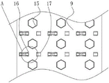
FIG. 4 is an enlarged schematic structural view of the fixing bracket with a soft limiting structure for transporting the snake robot of the present invention at the position A in FIG. 2;
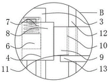
fig. 5 is an enlarged structural schematic diagram of a fixing bracket with a soft limiting structure for transporting a machine snake in fig. 1 at a position B.
In the figure: 1. a chassis; 2. a side bayonet; 3. side columns; 4. a column port; 5. a driving mechanism; 6. a driving block; 7. a driving spring; 8. a driving seat; 9. hanging the plate; 10. a disc hole; 11. a tray cover mechanism; 12. a wire rod; 13. a cover plate; 14. hanging buckles; 15. winding and buckling; 16. a soft limiting mechanism; 17. a limit buckle slot; 18. fixing the buckle; 19. buckling a mouth; 20. a slipknot; 21. a loose buckle slot; 22. a movable buckle block.
Detailed Description
The technical solutions in the embodiments of the present invention will be clearly and completely described below with reference to the drawings in the embodiments of the present invention, and it is obvious that the described embodiments are only a part of the embodiments of the present invention, and not all of the embodiments.
In the description of the present invention, "a plurality" means two or more unless otherwise specified; the terms "upper", "lower", "left", "right", "inner", "outer", "front", "rear", "head", "tail", and the like, indicate orientations or positional relationships based on the orientations or positional relationships shown in the drawings, are only for convenience in describing and simplifying the description, and do not indicate or imply that the referred devices or elements must have a specific orientation, be constructed in a specific orientation, and be operated, and thus are not to be construed as limiting the present invention, and furthermore, the terms "first", "second", "third", and the like are only used for descriptive purposes and are not to be construed as indicating or implying relative importance.
In the description of the present invention, it is to be noted that, unless otherwise explicitly specified or limited, the terms "connected" and "connected" are to be interpreted broadly, e.g., as being fixed or detachable or integrally connected; can be mechanically or electrically connected; they may be directly connected or indirectly connected through an intermediate, and those skilled in the art will understand the specific meaning of the above terms in the present invention in specific situations.
Referring to fig. 1-5, the present invention provides a technical solution: a fixing support with a soft limiting structure for transporting machine snakes comprises a base plate 1, side bayonets 2, side columns 3, column openings 4, a driving mechanism 5, a driving block 6, a driving spring 7, a driving seat 8, an upper plate 9, plate holes 10, a plate cover mechanism 11, wire rods 12, a cover plate 13, hanging buckles 14, winding buckles 15, a soft limiting mechanism 16, a limiting buckle groove 17, a fixing buckle 18, a buckle opening 19, a movable buckle 20, a movable buckle groove 21 and a movable buckle block 22, wherein the side bayonets 2 are arranged at the front end and the rear end of the base plate 1, the side columns 3 are fixed at the tops of the left end and the right end of the base plate 1, the column openings 4 are arranged in the upper, middle and lower ends of the side columns 3, the driving mechanism 5 is arranged on the outer side of the side columns 3, the upper plate 9 is connected to the inner side of the driving mechanism 5, the plate holes 10 are arranged at the front end and the rear end of the upper plate 9 in a penetrating manner, the plate cover mechanism 11 is positioned on the inner side of the plate holes, and a winding buckle 15 is fixed at the top end of the upper disc 9, and a soft limiting mechanism 16 is arranged on the outer side of the winding buckle 15.
The driving mechanism 5 comprises a driving block 6, a driving spring 7 and a driving seat 8, the driving block 6 is fixed in the middle of the driving mechanism 5, the driving spring 7 is connected to the outer wall of the driving block 6, the driving seat 8 is fixed on the front wall of the driving block 6, the driving seat 8 is movably connected with the side column 3, a slide way is arranged at the front end of the side column 3, the driving block 6 and the driving seat 8 form a fixed structure through welding through the slide way, the position of the driving seat 8 can be adjusted in a sliding mode through sliding among the driving block 6, the slide way and the column opening 4 for movable use, the driving seat 8 can automatically move to release force when being vibrated, and the protection performance of the driving seat 8 in use is improved.
The driving block 6 and the side column 3 form an elastic structure through the driving spring 7, the upper disc 9 and the driving seat 8 are fixedly connected, the number of the upper discs 9 is three, the driving seat 8 performing force unloading movement can have elastic force buffering performance through the elastic movement of the driving spring 7, so that the protection effect is enhanced, meanwhile, three groups of the upper discs 9 can be simultaneously protected according to the connection between the three groups of the driving seats 8 and the upper discs 9, and the three groups of the upper discs 9 are sequentially distributed at the middle end of the device body at equal intervals, so that the upper discs 9 can be more stable when being connected with the mechanical snake.
The wire rod cover mechanism 11 comprises a wire rod 12 and a cover disc 13, the wire rod 12 is fixed in the middle of the wire rod cover mechanism 11, the cover disc 13 is connected to the bottom end of the wire rod 12, the wire rod 12 is fixedly connected with the cover disc 13, the bottom end of the cover disc 13 is made of rubber, the wire rod 12 is symmetrical about the center of the cover disc 13, the cover disc 13 can be slidably adjusted to move through sliding between the wire rod 12 and a disc hole 10, the cover disc 13 can be covered on the outer side of a mechanical snake, the top end of the mechanical snake can be conveniently shielded and protected through pulling, the transportation safety of the mechanical snake is improved, multiple groups of wire rods 12 are mutually abutted and pressed, the wire rod 12 at the bottom end can be lifted to be in linkage adjustment, the wire rod 12 at the top end can also be pressed to be moved downwards in linkage, and the device body has excellent linkage.
The soft limiting mechanism 16 comprises a limiting buckle slot 17, a fixed buckle 18, a buckle opening 19, a movable buckle 20, a movable buckle slot 21 and a movable buckle block 22, the right end of the soft limiting mechanism 16 is provided with the limiting buckle slot 17, the left end of the soft limiting mechanism 16 is provided with the fixed buckle 18, the outer side of the fixed buckle 18 is provided with the buckle opening 19, the right end of the buckle opening 19 is provided with the movable buckle 20, the upper end and the lower end of the movable buckle 20 are both connected with the movable buckle block 22, the outer side of the movable buckle block 22 is provided with the movable buckle slot 21, the limiting buckle slot 17 is matched with the movable buckle 20 in shape structure, the upper end and the lower end of the limiting buckle slot 17 are both provided with limiting openings, the limiting buckle slot 17 and the buckle opening 19 are symmetrical around the center of the buckle 15, the movable buckle 20 can be well connected and arranged for use through the connection between the movable buckle 20 and the limiting buckle slot 17, when in use, the movable buckle 20 can be moved out from the right end of the buckle opening 19, and then the movable, the elastic force of the movable buckle 20 can automatically move to the left end of the limit buckle slot 17 and perform firm positioning through the adhesive tape adhered to the outer end of the movable buckle 20, the right end of the limit buckle slot 17 is open, and the left end of the limit buckle slot 17 is sealed, so that the limit buckle slot 17 can be conveniently used.
The movable buckle 20 forms a sliding structure with the upper disc 9 through a movable buckle groove 21 and a movable buckle block 22, the fixed buckle 18 is movably connected with the buckle opening 19, the movable buckle 20 and the fixed buckle 18 can be connected through the buckle opening 19, the movable buckle 20 can be embedded in the inner end of the buckle opening 19 for storage through the movable buckle groove 21 and the movable buckle block 22, meanwhile, the right ends of the buckle opening 19 and the movable buckle groove 21 are both in an open design, so that a user can conveniently take out the movable buckle 20 from the right ends of the movable buckle groove 21 and the buckle opening 19 for use, when the mechanical snake is used, the mechanical snake can be wound according to the winding buckle 15, then the movable buckle 20 passes through the mechanical snake and is buckled into the limiting buckle groove 17 for positioning, the mechanical snake can be limited and fixed according to the soft rubber belt between the movable buckle 20 and the fixed buckle 18, the use effect is good, and the mechanical snake can be sleeved in the hanging buckle 14 for suspension.
In conclusion, when the fixing support with the soft limiting structure is used for transporting the machine snake, the position of the driving seat 8 can be slidably adjusted to be movably used through sliding among the driving block 6, the slide way and the column port 4, the driving seat 8 can automatically move to unload force when being vibrated, the protection performance of the fixing support is improved, the driving seat 8 which performs unloading force can have elastic buffering performance through the elasticity of the driving spring 7, the protection effect of the fixing support is enhanced, meanwhile, three groups of upper disks 9 can be simultaneously protected according to the connection between the three groups of driving seats 8 and the upper disks 9, the three groups of upper disks 9 are sequentially and equidistantly distributed at the middle end of the device body, the upper disks 9 can be more stably connected with the machine snake, and the cover disks 13 can be slidably adjusted to move through sliding between the disk strips 12 and the disk holes 10, the cover disc 13 can be covered on the outer side of the mechanical snake, the top end of the mechanical snake can be conveniently pulled to shield and protect, the safety of the mechanical snake during transportation is improved, a plurality of groups of wire rods 12 are mutually supported and pressed, the wire rods 12 can be adjusted by lifting the cover disc 13 at the bottom end in a linkage manner, the wire rods 12 at the top end can be pressed down to move the cover disc 13 in a linkage manner, the device body has excellent linkage performance, the movable buckle 20 can be well connected and arranged to use the movable buckle 20 through the connection between the movable buckle 20 and the limit buckle groove 17, the movable buckle 20 can be moved out from the right end of the buckle opening 19 during use, then the movable buckle 20 is clamped into the right end of the limit buckle groove 17, the movable buckle 20 can be automatically moved to the left end of the limit buckle groove 17 by elastic force through the rubber belt adhered to the outer end of the movable buckle 20, the right end of the limit buckle groove 17 is open, the left end is sealed, and the limit buckle groove 17 can be conveniently used, can link up slipknot 20 and decide knot 18 through knot mouth 19, and slipknot 20 can the gomphosis store in knot mouth 19 inner through slipknot groove 21 and slipknot piece 22, simultaneously because the right-hand member of knot mouth 19 and slipknot groove 21 is the design of open type, and then can be good to take out slipknot 20 from slipknot groove 21 and the right-hand member of knot mouth 19 and use by the person of facilitating the use, when using, can twine the machine snake according to winding knot 15 earlier, then pass the slipknot 20 the machine snake and detain in spacing knot groove 17 and fix a position, can let the machine snake carry out spacing fixedly according to the soft rubber of slipknot 20 between the slipknot 20 and the deciding knot 18, have fine result of use, also can cup joint the machine snake and suspend in midair in the suspension knot 14 simultaneously.
The above description is only for the preferred embodiment of the present invention, but the scope of the present invention is not limited thereto, and any person skilled in the art should be considered to be within the technical scope of the present invention, and the technical solutions and the inventive concepts thereof according to the present invention should be equivalent or changed within the scope of the present invention.
Claims (9)
1. The utility model provides a machine snake transportation is with fixed bolster that has soft limit structure, includes chassis (1) and cover mechanism (11), its characterized in that: side bayonet socket (2) have all been seted up at both ends around chassis (1), and both ends top all is fixed with side post (3) about chassis (1), column mouth (4) have all been seted up to the upper and middle and lower extreme inside of side post (3), and the outside of side post (3) installs driving mechanism (5), the inboard of driving mechanism (5) links up hanging wall (9), and both ends all wear to be equipped with dish hole (10) around hanging wall (9), cover mechanism (11) are located the inboard of dish hole (10), both ends all settle hanging buckle (14) around hanging wall (9), and the top of hanging wall (9) is fixed with around knot (15), soft limit mechanism (16) are installed in the outside of around knot (15).
2. The fixing support with the soft limiting structure for the machine snake transportation according to claim 1, is characterized in that: the driving mechanism (5) comprises a driving block (6), a driving spring (7) and a driving seat (8), the driving block (6) is fixed in the middle of the driving mechanism (5), the driving spring (7) is connected to the outer wall of the driving block (6), and the driving seat (8) is fixed on the front wall of the driving block (6).
3. The fixing support with the soft limiting structure for the machine snake transportation according to claim 2, is characterized in that: the driving seat (8) is movably connected with the side column (3), a slide way is arranged at the front end of the side column (3), and the driving block (6) and the driving seat (8) form a fixed structure through welding.
4. The fixing support with the soft limiting structure for the machine snake transportation according to claim 2, is characterized in that: the driving block (6) and the side column (3) form an elastic structure through a driving spring (7), the upper disc (9) and the driving seat (8) are fixedly connected, and the number of the upper discs (9) is three.
5. The fixing support with the soft limiting structure for the machine snake transportation according to claim 1, is characterized in that: the wire rod cover mechanism (11) comprises a wire rod (12) and a cover plate (13), the wire rod (12) is fixed in the middle of the wire rod cover mechanism (11), and the cover plate (13) is connected to the bottom end of the wire rod (12).
6. A fixing support with a soft limiting structure for transporting a machine snake as claimed in claim 5, wherein: the wire rod (12) is fixedly connected with the cover disc (13), the bottom end of the cover disc (13) is made of rubber, and the wire rod (12) is symmetrical about the center of the cover disc (13).
7. The fixing support with the soft limiting structure for the machine snake transportation according to claim 1, is characterized in that: soft limit mechanism (16) are including spacing catching groove (17), decide knot (18), knot mouth (19), knot (20), knot groove (21) and knot piece (22) alive, and the right-hand member of soft limit mechanism (16) has seted up spacing catching groove (17), the left end of soft limit mechanism (16) is installed and is decided knot (18), and decides the outside of knot (18) and has seted up knot mouth (19), knot (20) are installed to the right-hand member of knot mouth (19), and the upper and lower both ends of knot (20) all link up knot piece (22) alive, knot groove (21) alive has been seted up in the outside of knot piece (22) alive.
8. A fixing support with a soft limiting structure for transporting a machine snake as claimed in claim 7, wherein: the limiting buckle groove (17) is matched with the movable buckle (20) in shape and structure, limiting openings are formed in the upper end and the lower end of the limiting buckle groove (17), and the limiting buckle groove (17) and the buckle opening (19) are symmetrical about the center of the winding buckle (15).
9. A fixing support with a soft limiting structure for transporting a machine snake as claimed in claim 7, wherein: the movable buckle (20) forms a sliding structure with the upper disc (9) through a movable buckle groove (21) and a movable buckle block (22), and the fixed buckle (18) is movably connected with the buckle opening (19).
Priority Applications (1)
| Application Number | Priority Date | Filing Date | Title |
|---|---|---|---|
| CN202010734124.8A CN112027351A (en) | 2020-07-28 | 2020-07-28 | Fixing support with soft limiting structure for transporting machine snakes |
Applications Claiming Priority (1)
| Application Number | Priority Date | Filing Date | Title |
|---|---|---|---|
| CN202010734124.8A CN112027351A (en) | 2020-07-28 | 2020-07-28 | Fixing support with soft limiting structure for transporting machine snakes |
Publications (1)
| Publication Number | Publication Date |
|---|---|
| CN112027351A true CN112027351A (en) | 2020-12-04 |
Family
ID=73583281
Family Applications (1)
| Application Number | Title | Priority Date | Filing Date |
|---|---|---|---|
| CN202010734124.8A Pending CN112027351A (en) | 2020-07-28 | 2020-07-28 | Fixing support with soft limiting structure for transporting machine snakes |
Country Status (1)
| Country | Link |
|---|---|
| CN (1) | CN112027351A (en) |
Citations (7)
| Publication number | Priority date | Publication date | Assignee | Title |
|---|---|---|---|---|
| CN205595963U (en) * | 2016-05-11 | 2016-09-21 | 开县联峰电机有限公司 | Rotor rack |
| CN206273527U (en) * | 2016-12-09 | 2017-06-23 | 上海三带特种工业线带有限公司 | One kind weaving roll stand |
| CN207985677U (en) * | 2017-09-19 | 2018-10-19 | 深圳市三美粘扣带有限公司 | Snap-gauge cargo bandage |
| CN109368038A (en) * | 2018-11-15 | 2019-02-22 | 哈尔滨理工大学 | A kind of electronic appliance has the storage equipment of interlayer anti-static effect |
| CN209177151U (en) * | 2018-10-09 | 2019-07-30 | 天津得利供应链管理有限公司 | A kind of novel logistics Special fixing belt formula pallet for transporting |
| CN209538749U (en) * | 2018-11-12 | 2019-10-25 | 贵州师范大学 | A kind of easy-to-dismount workshop support frame of steel structure |
| CN209921975U (en) * | 2019-01-16 | 2020-01-10 | 北京汉希工业科技有限公司 | Fixing support for bearing turnover box |
-
2020
- 2020-07-28 CN CN202010734124.8A patent/CN112027351A/en active Pending
Patent Citations (7)
| Publication number | Priority date | Publication date | Assignee | Title |
|---|---|---|---|---|
| CN205595963U (en) * | 2016-05-11 | 2016-09-21 | 开县联峰电机有限公司 | Rotor rack |
| CN206273527U (en) * | 2016-12-09 | 2017-06-23 | 上海三带特种工业线带有限公司 | One kind weaving roll stand |
| CN207985677U (en) * | 2017-09-19 | 2018-10-19 | 深圳市三美粘扣带有限公司 | Snap-gauge cargo bandage |
| CN209177151U (en) * | 2018-10-09 | 2019-07-30 | 天津得利供应链管理有限公司 | A kind of novel logistics Special fixing belt formula pallet for transporting |
| CN209538749U (en) * | 2018-11-12 | 2019-10-25 | 贵州师范大学 | A kind of easy-to-dismount workshop support frame of steel structure |
| CN109368038A (en) * | 2018-11-15 | 2019-02-22 | 哈尔滨理工大学 | A kind of electronic appliance has the storage equipment of interlayer anti-static effect |
| CN209921975U (en) * | 2019-01-16 | 2020-01-10 | 北京汉希工业科技有限公司 | Fixing support for bearing turnover box |
Similar Documents
| Publication | Publication Date | Title |
|---|---|---|
| ES2763223T3 (en) | Cradle | |
| CN112027351A (en) | Fixing support with soft limiting structure for transporting machine snakes | |
| ES2962978T3 (en) | Co-sleeping crib and corresponding frame | |
| KR200457630Y1 (en) | stretcher for first aid patient transfer | |
| JP2009107021A (en) | Welding wire tangling prevention device | |
| CN110626604A (en) | Blood supply transport case of intelligent security type | |
| CN211224416U (en) | Genetic disease screening and sampling box | |
| JP2012201469A (en) | Storage bag for protective pipe | |
| CN210131027U (en) | Multifunctional medical rehabilitation nursing bed | |
| CN217873753U (en) | Guard plate hinge mechanism for sickbed | |
| CN208552313U (en) | A kind of mental nursing hospital bed convenient for being fixed to patient | |
| CN213550953U (en) | Medical screen | |
| AU2011101475A4 (en) | An adjustable shoulder strap mechanism for baby stroller | |
| US8592696B2 (en) | Game carcass hanger and releasable weighing apparatus | |
| CN210843920U (en) | Anti-crush device for general nursing | |
| CN212625700U (en) | Lamination system | |
| BR102016015456A2 (en) | set and storage method | |
| CN220587919U (en) | Mosquito net with movable bottom for baby | |
| CN217614869U (en) | Test tube placement rack is used in nursing | |
| JP6543524B2 (en) | Sleeper device | |
| CN217612713U (en) | Athlete strength training equipment | |
| JP7472648B2 (en) | Power supply device and power supply method for flying object | |
| CN216624761U (en) | 5G communication network connection crystal head with close contact | |
| CN212221028U (en) | Plastic bag with holes | |
| CN213994448U (en) | Gynaecology and obstetrics's operation infusion mounted frame |
Legal Events
| Date | Code | Title | Description |
|---|---|---|---|
| PB01 | Publication | ||
| PB01 | Publication | ||
| SE01 | Entry into force of request for substantive examination | ||
| SE01 | Entry into force of request for substantive examination | ||
| RJ01 | Rejection of invention patent application after publication |
Application publication date: 20201204 |
|
| RJ01 | Rejection of invention patent application after publication |