CN112008958B - Vehicle plastic pipe leftover material trimming device for blow molding machine - Google Patents
Vehicle plastic pipe leftover material trimming device for blow molding machine Download PDFInfo
- Publication number
- CN112008958B CN112008958B CN202011135251.2A CN202011135251A CN112008958B CN 112008958 B CN112008958 B CN 112008958B CN 202011135251 A CN202011135251 A CN 202011135251A CN 112008958 B CN112008958 B CN 112008958B
- Authority
- CN
- China
- Prior art keywords
- pipe
- shaped
- cavity
- feeding chain
- blind hole
- Prior art date
- Legal status (The legal status is an assumption and is not a legal conclusion. Google has not performed a legal analysis and makes no representation as to the accuracy of the status listed.)
- Active
Links
Images


Classifications
-
- B—PERFORMING OPERATIONS; TRANSPORTING
- B29—WORKING OF PLASTICS; WORKING OF SUBSTANCES IN A PLASTIC STATE IN GENERAL
- B29C—SHAPING OR JOINING OF PLASTICS; SHAPING OF MATERIAL IN A PLASTIC STATE, NOT OTHERWISE PROVIDED FOR; AFTER-TREATMENT OF THE SHAPED PRODUCTS, e.g. REPAIRING
- B29C49/00—Blow-moulding, i.e. blowing a preform or parison to a desired shape within a mould; Apparatus therefor
- B29C49/42—Component parts, details or accessories; Auxiliary operations
- B29C49/72—Deflashing outside the mould
-
- B—PERFORMING OPERATIONS; TRANSPORTING
- B29—WORKING OF PLASTICS; WORKING OF SUBSTANCES IN A PLASTIC STATE IN GENERAL
- B29B—PREPARATION OR PRETREATMENT OF THE MATERIAL TO BE SHAPED; MAKING GRANULES OR PREFORMS; RECOVERY OF PLASTICS OR OTHER CONSTITUENTS OF WASTE MATERIAL CONTAINING PLASTICS
- B29B17/00—Recovery of plastics or other constituents of waste material containing plastics
- B29B17/04—Disintegrating plastics, e.g. by milling
-
- B—PERFORMING OPERATIONS; TRANSPORTING
- B29—WORKING OF PLASTICS; WORKING OF SUBSTANCES IN A PLASTIC STATE IN GENERAL
- B29C—SHAPING OR JOINING OF PLASTICS; SHAPING OF MATERIAL IN A PLASTIC STATE, NOT OTHERWISE PROVIDED FOR; AFTER-TREATMENT OF THE SHAPED PRODUCTS, e.g. REPAIRING
- B29C37/00—Component parts, details, accessories or auxiliary operations, not covered by group B29C33/00 or B29C35/00
- B29C37/02—Deburring or deflashing
-
- B—PERFORMING OPERATIONS; TRANSPORTING
- B29—WORKING OF PLASTICS; WORKING OF SUBSTANCES IN A PLASTIC STATE IN GENERAL
- B29C—SHAPING OR JOINING OF PLASTICS; SHAPING OF MATERIAL IN A PLASTIC STATE, NOT OTHERWISE PROVIDED FOR; AFTER-TREATMENT OF THE SHAPED PRODUCTS, e.g. REPAIRING
- B29C48/00—Extrusion moulding, i.e. expressing the moulding material through a die or nozzle which imparts the desired form; Apparatus therefor
- B29C48/25—Component parts, details or accessories; Auxiliary operations
- B29C48/275—Recovery or reuse of energy or materials
- B29C48/277—Recovery or reuse of energy or materials of materials
-
- B—PERFORMING OPERATIONS; TRANSPORTING
- B29—WORKING OF PLASTICS; WORKING OF SUBSTANCES IN A PLASTIC STATE IN GENERAL
- B29C—SHAPING OR JOINING OF PLASTICS; SHAPING OF MATERIAL IN A PLASTIC STATE, NOT OTHERWISE PROVIDED FOR; AFTER-TREATMENT OF THE SHAPED PRODUCTS, e.g. REPAIRING
- B29C48/00—Extrusion moulding, i.e. expressing the moulding material through a die or nozzle which imparts the desired form; Apparatus therefor
- B29C48/25—Component parts, details or accessories; Auxiliary operations
- B29C48/285—Feeding the extrusion material to the extruder
- B29C48/288—Feeding the extrusion material to the extruder in solid form, e.g. powder or granules
-
- B—PERFORMING OPERATIONS; TRANSPORTING
- B29—WORKING OF PLASTICS; WORKING OF SUBSTANCES IN A PLASTIC STATE IN GENERAL
- B29C—SHAPING OR JOINING OF PLASTICS; SHAPING OF MATERIAL IN A PLASTIC STATE, NOT OTHERWISE PROVIDED FOR; AFTER-TREATMENT OF THE SHAPED PRODUCTS, e.g. REPAIRING
- B29C49/00—Blow-moulding, i.e. blowing a preform or parison to a desired shape within a mould; Apparatus therefor
- B29C49/02—Combined blow-moulding and manufacture of the preform or the parison
- B29C49/04—Extrusion blow-moulding
-
- B—PERFORMING OPERATIONS; TRANSPORTING
- B29—WORKING OF PLASTICS; WORKING OF SUBSTANCES IN A PLASTIC STATE IN GENERAL
- B29C—SHAPING OR JOINING OF PLASTICS; SHAPING OF MATERIAL IN A PLASTIC STATE, NOT OTHERWISE PROVIDED FOR; AFTER-TREATMENT OF THE SHAPED PRODUCTS, e.g. REPAIRING
- B29C49/00—Blow-moulding, i.e. blowing a preform or parison to a desired shape within a mould; Apparatus therefor
- B29C49/42—Component parts, details or accessories; Auxiliary operations
- B29C49/72—Deflashing outside the mould
- B29C2049/725—Means for removing the deflashed parts from the deflashing area, e.g. burrs being removed from the deflashing area by a conveyor
-
- B—PERFORMING OPERATIONS; TRANSPORTING
- B29—WORKING OF PLASTICS; WORKING OF SUBSTANCES IN A PLASTIC STATE IN GENERAL
- B29L—INDEXING SCHEME ASSOCIATED WITH SUBCLASS B29C, RELATING TO PARTICULAR ARTICLES
- B29L2023/00—Tubular articles
-
- Y—GENERAL TAGGING OF NEW TECHNOLOGICAL DEVELOPMENTS; GENERAL TAGGING OF CROSS-SECTIONAL TECHNOLOGIES SPANNING OVER SEVERAL SECTIONS OF THE IPC; TECHNICAL SUBJECTS COVERED BY FORMER USPC CROSS-REFERENCE ART COLLECTIONS [XRACs] AND DIGESTS
- Y02—TECHNOLOGIES OR APPLICATIONS FOR MITIGATION OR ADAPTATION AGAINST CLIMATE CHANGE
- Y02P—CLIMATE CHANGE MITIGATION TECHNOLOGIES IN THE PRODUCTION OR PROCESSING OF GOODS
- Y02P70/00—Climate change mitigation technologies in the production process for final industrial or consumer products
- Y02P70/10—Greenhouse gas [GHG] capture, material saving, heat recovery or other energy efficient measures, e.g. motor control, characterised by manufacturing processes, e.g. for rolling metal or metal working
-
- Y—GENERAL TAGGING OF NEW TECHNOLOGICAL DEVELOPMENTS; GENERAL TAGGING OF CROSS-SECTIONAL TECHNOLOGIES SPANNING OVER SEVERAL SECTIONS OF THE IPC; TECHNICAL SUBJECTS COVERED BY FORMER USPC CROSS-REFERENCE ART COLLECTIONS [XRACs] AND DIGESTS
- Y02—TECHNOLOGIES OR APPLICATIONS FOR MITIGATION OR ADAPTATION AGAINST CLIMATE CHANGE
- Y02W—CLIMATE CHANGE MITIGATION TECHNOLOGIES RELATED TO WASTEWATER TREATMENT OR WASTE MANAGEMENT
- Y02W30/00—Technologies for solid waste management
- Y02W30/50—Reuse, recycling or recovery technologies
- Y02W30/62—Plastics recycling; Rubber recycling
Landscapes
- Engineering & Computer Science (AREA)
- Mechanical Engineering (AREA)
- Manufacturing & Machinery (AREA)
- Physics & Mathematics (AREA)
- Thermal Sciences (AREA)
- Environmental & Geological Engineering (AREA)
- Processing And Handling Of Plastics And Other Materials For Molding In General (AREA)
Abstract
The utility model provides a vehicle plastics pipe fitting leftover bits side cut device for blowing machine, including the blade holder, one side fixed mounting cutter of blade holder, the first telescopic link of opposite side fixed mounting of blade holder, be equipped with the cavity in the blade holder, one side opening of cavity and the top that is located the cutter, be equipped with in the cavity and be used for sending the leftover bits to cutting mechanism's feeding mechanism, cutting mechanism is located the feeding mechanism top, the blind hole is seted up to the bottom surface of blade holder, be equipped with the annular slab of center line altogether with it in the blind hole, the lower extreme of the top surface fixed connection several second telescopic link of annular slab, the bottom surface of the common fixed connection ring gear in upper end. The invention is particularly suitable for extrusion blow molding, burrs of a product outside a mold can be cut off before mold splitting, then the burrs are trimmed, the cut burrs and trimmed scraps enter a material box through an air inlet pipe, and after the burrs and the trimmed scraps are accumulated for a period of time, a user can open a valve on a discharge pipe to guide the burrs and scraps into a feed hopper of an extrusion mechanism of a blow molding machine, so that raw materials can be fully recovered.
Description
Technical Field
The invention belongs to the field of blow molding, and particularly relates to a vehicle plastic pipe leftover material trimming device for a blow molding machine.
Background
The thermoplastic resin is extruded or injection molded to obtain tubular plastic parison, which is hot or heated to soften, and then placed in a split mold, after the mold is closed, compressed air is introduced into the parison to blow the plastic parison to cling to the inner wall of the mold, and after cooling and demolding, various hollow products are obtained. This is the blow molding manufacturing process. However, for extrusion blow molding, trimming of flash and burr is often accompanied, and it is common to match manual trimming, and some trimming is performed by using an automatic device after demolding, but this method needs to additionally configure a clamping structure of a blow-molded part, and the structure is complicated, and in addition, the precision requirement for automatic trimming is high, which increases the production cost.
Disclosure of Invention
The invention provides a vehicle plastic pipe leftover material trimming device for a blow molding machine, which is used for solving the defects in the prior art.
The invention is realized by the following technical scheme:
a vehicle plastic pipe leftover trimming device for a blow molding machine comprises a cutter holder, wherein a cutter is fixedly installed on one side of the cutter holder, a first telescopic rod is fixedly installed on the other side of the cutter holder, a cavity is arranged in the cutter holder, one side of the cavity is open and is positioned above the cutter, a feeding mechanism used for conveying leftover materials to a cutting mechanism is arranged in the cavity, the cutting mechanism is positioned above the feeding mechanism, a blind hole is formed in the bottom surface of the cutter holder, a ring-shaped plate which is concentric with the blind hole is arranged in the blind hole, the top surface of the ring-shaped plate is fixedly connected with the lower ends of a plurality of second telescopic rods, the upper ends of the second telescopic rods are fixedly connected with the bottom surface of a gear ring, the gear ring is connected with the side wall of the blind hole through a bearing, a gear meshed with the gear ring is arranged in the gear ring, a motor, the air inlet pipe is rotatably connected with one end of the branch pipe, a V-shaped pipe is arranged at the bottom of the annular plate and connected with the other end of the branch pipe, an arc-shaped knife is arranged below the V-shaped pipe, the opening of the arc-shaped knife faces downwards, two ends of the V-shaped pipe are respectively positioned on two sides of the arc-shaped knife, the part of the air inlet pipe, which is positioned in the cavity, is connected with a hopper, and the hopper faces; the other end fixed connection workbin of intake pipe, the workbin is fixed connection outlet duct and the one end of arranging the material pipe respectively, the negative pressure suction device is connected to the other end of outlet duct, be equipped with the filter screen between intake pipe and the outlet duct, it is equipped with the valve to arrange the material pipe, be equipped with the reciprocal lead screw that is on a parallel with the filter screen in the workbin, the cooperation is equipped with the screw on the reciprocal lead screw, the periphery fixed mounting scraper blade of screw, the scraper blade perpendicular to filter screen and contact fit with it, be equipped with two intermeshing's bevel gear in the workbin, one of them bevel gear fixed mounting is in the periphery of reciprocal lead screw, another bevel gear is connected with workbin.
According to the vehicle plastic pipe leftover trimming device for the blow molding machine, the feeding mechanism comprises three feeding chain rollers and a feeding chain plate, the three feeding chain rollers are connected with the feeding chain plate, and the feeding chain plate is of a V-shaped structure with a downward opening.
According to the vehicle plastic pipe leftover trimming device for the blow molding machine, the rotating roller is arranged at the opening of the cavity, and the plurality of rows of nail spines are fixedly installed on the periphery of the rotating roller.
According to the vehicle plastic pipe leftover trimming device for the blow molding machine, the inner side and the outer side of the feeding chain plate are respectively provided with the carrier roller, the carrier rollers outside the feeding chain plate are positioned at the corners of the feeding chain plate, and the carrier rollers inside the feeding chain plate are positioned right below the cutting mechanism.
According to the vehicle plastic pipe leftover trimming device for the blow molding machine, the cutting mechanism comprises the same rotary roller and the plurality of annular cutters, the annular cutters are fixedly arranged on the periphery of the corresponding rotary roller, and the distance between every two adjacent annular cutters is the same.
According to the vehicle plastic pipe leftover trimming device for the blow molding machine, the back of the arc-shaped knife is sequentially provided with the polishing piece and the brush which are also of the arc-shaped structure.
The invention has the advantages that: the invention is particularly suitable for extrusion blow molding, burrs of a product outside a mold can be cut off before mold splitting, then the burrs are trimmed, the cut burrs and trimmed scraps enter a material box through an air inlet pipe, and after the burrs and the trimmed scraps are accumulated for a period of time, a user can open a valve on a discharge pipe to guide the burrs and scraps into a feed hopper of an extrusion mechanism of a blow molding machine, so that raw materials can be fully recovered. First telescopic link extends and drives the blade holder and removes, the bottom surface parallel and level of blade holder is in the top surface of mould, consequently can downcut the deckle edge when the cutter removes along with the blade holder, the deckle edge that downcuts gets into in the cavity along the wedge face of cutter, send to the hopper in by feeding mechanism afterwards, above-mentioned in-process cutting mechanism can shred the deckle edge, under the effect of negative pressure attraction force, these crushed aggregates get into in the inlet duct from the hopper, when the annular plate removes directly over the mould, first telescopic link stop the removal, this process accessible is connected with the control system electricity in order to realize accurate control, then the second telescopic link extends and drives the annular plate and moves down, the arc sword is detained on the open end border of pipe fitting, then the motor begins to work, through the meshing of gear and ring gear, thereby make the arc sword rotate, can advance to the pipe end and further maintain, and can avoid the, reduce the probability of follow-up work step with workman's fish tail, the piece passes through V type pipe, branch pipe gets into in the intake pipe, under the drive of air current, the turbine rotates, and can make the bevel gear rotate thereupon through belt mechanism, finally make reciprocal lead screw be in the rotation state, the screw is along its reciprocating motion, scraper blade on it contacts with the filter screen all the time, can scrape the piece that adsorbs on the filter screen to both sides, in order to avoid influencing the air flow, after using the completion, close negative pressure suction device, concentrate on the piece of both sides and fall to the bottom of workbin at the action of gravity, and through the continuous attraction of negative pressure suction, can also avoid falling into inside piece pipe fitting or the mould, reduce the follow-up degree of difficulty of repairing to the pipe fitting, and can avoid clearing up the mould between the compound.
Drawings
In order to more clearly illustrate the embodiments of the present invention or the technical solutions in the prior art, the drawings needed to be used in the description of the embodiments or the prior art will be briefly introduced below, and it is obvious that the drawings in the following description are some embodiments of the present invention, and for those skilled in the art, other drawings can be obtained according to these drawings without creative efforts.
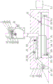
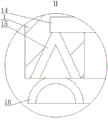
FIG. 1 is a schematic structural view of the present invention; FIG. 2 is a schematic view of the cutting mechanism; FIG. 3 is an enlarged view of the view from the direction A of FIG. 1; FIG. 4 is an enlarged view of section I of FIG. 1; fig. 5 is a partial enlarged view of ii of fig. 1.
Reference numerals: 1. the device comprises a tool apron, 2, a cutter, 3, a first telescopic rod, 4, a cavity, 5, a blind hole, 8, an annular plate, 9, a second telescopic rod, 10, a gear ring, 11, a gear, 12, a motor, 13, an air inlet pipe, 14, a branch pipe, 15, a V-shaped pipe, 16, an arc-shaped cutter, 17, a hopper, 18, a bin, 19, an air outlet pipe, 20, a filter screen, 21, a discharge pipe, 22, a reciprocating screw rod, 23, a nut, 24, a scraper, 25, a bevel gear, 26, a turbine, 27, a feeding chain roller, 28, a feeding chain plate, 29, a rotating roller, 30, a nail thorn, 31, a carrier roller, 32 and an annular cutter.
Detailed Description
In order to make the objects, technical solutions and advantages of the embodiments of the present invention clearer, the technical solutions in the embodiments of the present invention will be clearly and completely described below with reference to the drawings in the embodiments of the present invention, and it is obvious that the described embodiments are some, but not all, embodiments of the present invention. All other embodiments, which can be derived by a person skilled in the art from the embodiments given herein without making any creative effort, shall fall within the protection scope of the present invention.
A vehicle plastic pipe leftover material trimming device for a blow molding machine comprises a cutter holder 1, wherein a cutter 2 is fixedly installed on one side of the cutter holder 1, a first telescopic rod 3 is fixedly installed on the other side of the cutter holder 1, a hydraulic cylinder, an electric push rod, an air cylinder and the like can be selected, a cavity 4 is arranged in the cutter holder 1, one side of the cavity 4 is opened and is positioned above the cutter 2, a feeding mechanism used for conveying leftover materials to a cutting mechanism is arranged in the cavity 4, the cutting mechanism is positioned above the feeding mechanism, a blind hole 5 is formed in the bottom surface of the cutter holder 1, an annular plate 8 which is concentric with the blind hole 5 is arranged in the blind hole 5, the top surface of the annular plate 8 is fixedly connected with the lower ends of a plurality of second telescopic rods 9, the electric push rod is selected and connected with a power circuit, a sliding contact body such as an electric brush structure is adopted to connect a power supply, the upper ends of, a gear 11 meshed with the gear is arranged in the gear ring 10, a motor 12 is fixedly installed on the top surface of the blind hole 5, the motor 12 is connected with a power circuit, the output end of the motor 12 is connected with the gear 11, the top of the tool apron 1 is fixedly connected with one end of an air inlet pipe 13, the air inlet pipe 13 is respectively communicated with the cavity 4 and the interior of the blind hole 5, the air inlet pipe 13 is rotatably connected with one end of a branch pipe 14, the branch pipe 14 is of an L-shaped structure, soft materials are selected to adapt to the movement of the annular plate 8, the bending part of the branch pipe is positioned in the annular plate 8 and cannot influence the meshing between the gear 11 and the gear ring 10, a V-shaped pipe 15 is arranged at the bottom of the annular plate 8, the V-shaped pipe 15 is embedded in the annular plate 8 and has a downward opening, the V-shaped pipe 15 is connected with the other end of the branch pipe 14, an arc, the thin end of the hopper 17 is a tubular structure with openings at two ends, so that the suction force can be concentrated, and the hopper 17 faces the feeding mechanism; the other end of the air inlet pipe 13 is fixedly connected with a material box 18, the material box 18 is respectively and fixedly connected with one end of an air outlet pipe 19 and one end of a material discharge pipe 21, one side of the material box 18 close to the material discharge pipe 21 is of a concave structure, so that leftover materials are gathered towards the material discharge pipe 21 under the action of gravity, the other end of the material discharge pipe 21 is connected with a feed hopper of an extrusion mechanism of a blow molding machine, the other end of the air outlet pipe 19 is connected with a negative pressure suction device, the negative pressure suction device can be a negative pressure fan, a vacuum pump and the like, a filter screen 20 is arranged between the air inlet pipe 13 and the air outlet pipe 19, the periphery of the filter screen 20 is fixedly connected with the inner wall of the material box 18, the air inlet pipe 13 and the air outlet pipe 19 share a central line, the material discharge pipe 21 and the air inlet pipe 13 are positioned on the same side, one end of the reciprocating screw is connected with the inner wall of the feed box 18 through a bearing, a screw nut 23 is arranged on the reciprocating screw 22 in a matching mode, a scraping plate 24 is fixedly arranged on the periphery of the screw nut 23, the scraping plate 24 is perpendicular to and in contact fit with the filter screen 20, two bevel gears 25 which are meshed with each other are arranged in the feed box 18, one bevel gear 25 is fixedly arranged on the periphery of the reciprocating screw 22, the other bevel gear 25 is rotatably connected with the inner wall of the feed box 18, a turbine 26 is rotatably arranged in the feed box 18, and the turbine 26 is connected with the other bevel. The invention is particularly suitable for extrusion blow molding, burrs of a product outside a mold can be cut off before mold splitting, then the burrs are trimmed, the cut burrs and trimmed scraps enter a material box 18 through an air inlet pipe 13, after the burrs are accumulated for a period of time, a user can open a valve on a discharge pipe 21 to guide the burrs into a feed hopper of an extrusion mechanism of a blow molding machine, and raw materials can be fully recovered. The first telescopic rod 3 extends to drive the tool apron 1 to move, the bottom surface of the tool apron 1 is flush with the top surface of the die, therefore, when the cutter 2 moves along with the tool apron 1, burrs can be cut off, the cut burrs enter the cavity 4 along the wedge-shaped surface of the cutter 2 and are then conveyed into the hopper 17 by the feeding mechanism, the cutting mechanism can cut off the burrs in the process, the crushed aggregates enter the air inlet pipe 13 from the hopper 17 under the action of negative pressure suction force, when the annular plate 8 moves to the position right above the die, the first telescopic rod 3 stops moving, the process can be accurately controlled by being electrically connected with a control system, then the second telescopic rod 9 extends to drive the annular plate 8 to move downwards, the arc-shaped knife 16 is buckled on the edge of the opening end of the pipe fitting, then the motor 12 starts to work, through the meshing of the gear 11 and the gear ring 10, so that the arc-shaped knife 16 rotates, the pipe, and can avoid the pipe end to form sharp edge, reduce the probability that the follow-up work step will workman the fish tail, the piece passes through V type pipe 15, branch pipe 14 gets into in the intake pipe 13, under the drive of air current, turbine 26 rotates, and can make bevel gear 25 rotate along with it through belt mechanism, finally make reciprocal lead screw 22 be in the rotation state, screw 23 is along its reciprocating motion, scraper blade 24 on it contacts with filter screen 20 all the time, can scrape the piece that adsorbs on filter screen 20 to both sides, in order not to influence the air flow, after using the completion, close the negative pressure suction device, the piece that concentrates on both sides falls to the bottom of workbin 18 under the action of gravity, and through the continuous suction of negative pressure suction, can also avoid the piece to fall into inside the pipe fitting or the mould, reduce the follow-up maintenance degree of difficulty to the pipe fitting, and can avoid clearing up the mould between the compound.
Specifically, as shown in fig. 1, the feeding mechanism of the present embodiment includes three feeding chain rollers 27 and feeding chain plates 28, the three feeding chain rollers 27 are all connected to the feeding chain plates 28, one of the feeding chain rollers 28 is connected to an output end of a stepping motor, etc., the feeding chain plate 28 is a V-shaped structure with an opening facing downward, an angle of the V-shaped structure is 135 + 170 °, a right portion is in a horizontal state, and a left portion faces the cutting blade 2. The cutter 2 moves towards the cavity 4 along the wedge-shaped surface of the cutter 2 after cutting off leftover materials outside the die after die assembly, and then is conveyed towards the hopper 17 by the feeding mechanism, and is cracked by the cutting mechanism in the conveying process, and the chain plate type structure is also favorable for improving the stability of the conveying process, particularly during cutting.
Specifically, as shown in fig. 1, the opening of the cavity 4 described in this embodiment is provided with a rotating roller 29, a plurality of rows of nails 30 are fixedly installed on the periphery of the rotating roller 29, the nails 30 are uniformly distributed on the periphery of the rotating roller 29, one end of the rotating roller 29 is rotatably connected to the inner wall of the cavity 4 through a bearing or the like, and the other end of the rotating roller 29 is connected to the output end of the stepping motor or the like through a coupling or other structure. The leftover materials cut by the cutter 2 outside the die assembly are not completely solidified, the nail spurs 30 can penetrate into the leftover materials, the leftover materials can be conveyed to the feeding mechanism more stably along with the rotation of the rotary roller 29, the rotation direction of the rotary roller 29 is the same as that of the feeding chain roller 27, and the leftover materials can be prevented from sliding off from the left side part of the feeding chain roller 28.
Further, as shown in fig. 1, the feeding chain plate 28 of the present embodiment has an inner idler 31 and an outer idler 31, the idler 31 outside the feeding chain plate 28 is located at a corner of the feeding chain plate 28, and the idler 31 inside the feeding chain plate 28 is located right below the cutting mechanism. The structure can better maintain the shape of the feeding chain plate 28 so as to prevent the feeding chain plate from being scratched and damaged with the cavity 4, and can also counteract the force applied by the cutting mechanism so as to prevent the feeding chain plate 28 from being inwards sunken.
Furthermore, as shown in fig. 2, the cutting mechanism according to the present embodiment includes the same rotating roller 29 and a plurality of annular knives 32, the annular knives 32 are fixedly mounted on the periphery of the corresponding rotating roller 29, and the distance between two adjacent annular knives 32 is the same. The periphery of the annular knife 32 is in contact with the periphery of the feeding chain plate 28, so that the leftover materials can be uniformly cut into small pieces.
Further, not shown in the drawings, the back of the arc-shaped knife 16 of the present embodiment is sequentially designed with a polishing piece and a brush which are also arc-shaped. After 16 maintain the shaping pipe fitting as the arc sword, the piece of polishing and brush can further clear up burr and dust on the pipe fitting, and the while cooperation is with negative pressure suction, can avoid burr dust etc. to fall into in mould or the pipe fitting.
Finally, it should be noted that: the above examples are only intended to illustrate the technical solution of the present invention, but not to limit it; although the present invention has been described in detail with reference to the foregoing embodiments, it will be understood by those of ordinary skill in the art that: the technical solutions described in the foregoing embodiments may still be modified, or some technical features may be equivalently replaced; and such modifications or substitutions do not depart from the spirit and scope of the corresponding technical solutions of the embodiments of the present invention.
Claims (6)
1. The utility model provides a vehicle plastics pipe fitting leftover bits side cut device for blowing machine, includes blade holder (1), one side fixed mounting cutter (2) of blade holder (1), the first telescopic link of opposite side fixed mounting (3) of blade holder (1), its characterized in that: a cavity (4) is arranged in the tool apron (1), one side of the cavity (4) is opened and is positioned above the cutter (2), a feeding mechanism used for conveying leftover materials to a cutting mechanism is arranged in the cavity (4), the cutting mechanism is positioned above the feeding mechanism, a blind hole (5) is formed in the bottom surface of the tool apron (1), a ring-shaped plate (8) which is concentric with the blind hole (5) is arranged in the blind hole (5), the top surface of the ring-shaped plate (8) is fixedly connected with the lower ends of a plurality of second telescopic rods (9), the upper ends of the second telescopic rods (9) are fixedly connected with the bottom surface of a gear ring (10) together, the gear ring (10) is connected with the side wall of the blind hole (5) through a bearing, a gear (11) which is meshed with the gear ring (10) is arranged in the gear ring (10), a motor (12) is fixedly installed on the top surface of the blind hole (5), the air inlet pipe (13) is communicated with the interiors of the cavity (4) and the blind hole (5) respectively, the air inlet pipe (13) is rotatably connected with one end of the branch pipe (14), a V-shaped pipe (15) is arranged at the bottom of the annular plate (8), the V-shaped pipe (15) is connected with the other end of the branch pipe (14), an arc-shaped knife (16) is arranged below the V-shaped pipe (15), the opening of the arc-shaped knife (16) faces downwards, two ends of the V-shaped pipe (15) are located on two sides of the arc-shaped knife (16) respectively, a hopper (17) is connected to the part of the air inlet pipe (13) located in the; the other end of the air inlet pipe (13) is fixedly connected with a material box (18), the material box (18) is respectively and fixedly connected with an air outlet pipe (19) and one end of a material discharging pipe (21), the other end of the air outlet pipe (19) is connected with a negative pressure suction device, a filter screen (20) is arranged between the air inlet pipe (13) and the air outlet pipe (19), a valve is arranged on the material discharging pipe (21), a reciprocating lead screw (22) parallel to the filter screen (20) is arranged in the material box (18), a screw nut (23) is arranged on the reciprocating lead screw (22) in a matching manner, a scraper (24) is fixedly arranged on the periphery of the screw nut (23), the scraper (24) is perpendicular to the filter screen (20) and is in contact fit with the filter screen, two bevel gears (25) which are meshed with each other are arranged in the material box (18), one bevel gear (25) is fixedly arranged on the periphery of the reciprocating, the turbine (26) is connected with another bevel gear (25) through a belt mechanism.
2. The apparatus of claim 1, wherein the apparatus comprises: the feeding mechanism comprises three feeding chain rollers (27) and a feeding chain plate (28), the three feeding chain rollers (27) are connected with the feeding chain plate (28), and the feeding chain plate (28) is of a V-shaped structure with a downward opening.
3. The apparatus of claim 2, wherein the apparatus comprises: the opening of cavity (4) be equipped with and change roller (29), the periphery of changeing roller (29) fixed mounting several rows of nail thorn (30).
4. The apparatus of claim 2, wherein the apparatus comprises: the inside and the outside of the feeding chain plate (28) are respectively provided with a carrier roller (31), the carrier rollers (31) outside the feeding chain plate (28) are positioned at the corners of the feeding chain plate (28), and the carrier rollers (31) inside the feeding chain plate (28) are positioned right below the cutting mechanism.
5. The apparatus of claim 1, wherein the apparatus comprises: the cutting mechanism comprises the same rotating roller (29) and a plurality of annular cutters (32), the annular cutters (32) are fixedly arranged on the periphery of the corresponding rotating roller (29), and the distance between every two adjacent annular cutters (32) is the same.
6. The apparatus of claim 1, wherein the apparatus comprises: the back of the arc-shaped knife (16) is sequentially provided with a polishing piece and a hairbrush which are also arc-shaped structures.
Priority Applications (1)
| Application Number | Priority Date | Filing Date | Title |
|---|---|---|---|
| CN202011135251.2A CN112008958B (en) | 2020-10-22 | 2020-10-22 | Vehicle plastic pipe leftover material trimming device for blow molding machine |
Applications Claiming Priority (1)
| Application Number | Priority Date | Filing Date | Title |
|---|---|---|---|
| CN202011135251.2A CN112008958B (en) | 2020-10-22 | 2020-10-22 | Vehicle plastic pipe leftover material trimming device for blow molding machine |
Publications (2)
| Publication Number | Publication Date |
|---|---|
| CN112008958A CN112008958A (en) | 2020-12-01 |
| CN112008958B true CN112008958B (en) | 2021-02-26 |
Family
ID=73528357
Family Applications (1)
| Application Number | Title | Priority Date | Filing Date |
|---|---|---|---|
| CN202011135251.2A Active CN112008958B (en) | 2020-10-22 | 2020-10-22 | Vehicle plastic pipe leftover material trimming device for blow molding machine |
Country Status (1)
| Country | Link |
|---|---|
| CN (1) | CN112008958B (en) |
Families Citing this family (1)
| Publication number | Priority date | Publication date | Assignee | Title |
|---|---|---|---|---|
| CN113290819B (en) * | 2021-05-21 | 2022-12-20 | 昆山市曦贵高分子材料有限公司 | High-utilization-rate production system for thermoplastic elastomer particle raw materials |
Family Cites Families (9)
| Publication number | Priority date | Publication date | Assignee | Title |
|---|---|---|---|---|
| US5603249A (en) * | 1995-04-19 | 1997-02-18 | R & B Machine Tool Company | Trim cutter apparatus for blow molded articles |
| JPH09300368A (en) * | 1996-05-15 | 1997-11-25 | Fujimori Kogyo Kk | Trimming treatment apparatus |
| JP5044132B2 (en) * | 2005-07-07 | 2012-10-10 | 富士フイルム株式会社 | Manufacturing method and manufacturing equipment of solid electrolyte film |
| CN206140604U (en) * | 2016-10-26 | 2017-05-03 | 天津登峰卫生用品材料有限公司 | Waste recovery device of cutting edge equipment |
| CN107263579A (en) * | 2017-08-07 | 2017-10-20 | 四川南格尔生物科技有限公司 | A kind of plastic tube Scissoring device and method of cutting out |
| CN208290462U (en) * | 2018-06-08 | 2018-12-28 | 合肥泰宇汽车零部件有限公司 | A kind of automotive plastic parts trimming for forming mold |
| CN208646001U (en) * | 2018-07-20 | 2019-03-26 | 武汉环岛塑胶包装有限责任公司 | Blow moulding machine plastics spout leftover pieces trimming device |
| CN211105539U (en) * | 2019-08-19 | 2020-07-28 | 杭州盈润塑料包装有限公司 | Plastic bottle mouth leftover material trimming device for blow molding machine |
| CN210849563U (en) * | 2019-09-11 | 2020-06-26 | 上海芯尚电子科技有限公司 | Plastic tubing remove thorn device |
-
2020
- 2020-10-22 CN CN202011135251.2A patent/CN112008958B/en active Active
Also Published As
| Publication number | Publication date |
|---|---|
| CN112008958A (en) | 2020-12-01 |
Similar Documents
| Publication | Publication Date | Title |
|---|---|---|
| CN110561724B (en) | Pull rod bottle blowing machine | |
| CN112008958B (en) | Vehicle plastic pipe leftover material trimming device for blow molding machine | |
| CN115230109B (en) | Extrusion molding device is used in production of plastics dysmorphism material | |
| CN111716655A (en) | Injection mold with automatic deburring mechanism for mold opening and closing and use method | |
| CN111113966B (en) | Power pipeline machining method | |
| CN109732809B (en) | Waste plastic crusher | |
| CN113263695B (en) | Multi-cavity full-automatic demolding injection molding mold | |
| CN214726389U (en) | Injection molding bottle blowing machine | |
| CN210651964U (en) | Conveying device for tire tread trimming return rubber | |
| CN210634109U (en) | Rotary cutter for cutting burrs of blow molding machine | |
| CN110524759B (en) | Injection mold with trimming function | |
| CN211730146U (en) | Automatic recovery unit of open rubber mixing machine clout | |
| CN211074830U (en) | Abrasive extrusion forming device | |
| CN212736099U (en) | A cut machinery for food processing | |
| CN210651965U (en) | Device for simultaneously preparing treads with various widths | |
| CN217670849U (en) | Automatic water gap shearing equipment of injection mold for plastic joint | |
| CN215434869U (en) | Injection molding device capable of quickly cleaning waste materials and collecting waste materials | |
| CN218315025U (en) | Injection molding runner shearing mechanism | |
| CN204869611U (en) | Bottle blowing machine with mill a mouthful function | |
| CN109228185A (en) | It is a kind of to remove regrinding-material cutter plastic mould automatically | |
| CN218462278U (en) | Full-automatic multifunctional fine cutting equipment for automobile glass wool groove | |
| CN214111430U (en) | Automatic blowing mould of blank | |
| CN211104377U (en) | Automatic mechanism of cutting tubular product | |
| CN219130906U (en) | Sweeps clearance mechanism for milling machine | |
| CN215619733U (en) | Mechanical arm linkage automatic shearing device |
Legal Events
| Date | Code | Title | Description |
|---|---|---|---|
| PB01 | Publication | ||
| PB01 | Publication | ||
| SE01 | Entry into force of request for substantive examination | ||
| SE01 | Entry into force of request for substantive examination | ||
| GR01 | Patent grant | ||
| GR01 | Patent grant |