CN112005450B - Hybrid bus for bus system - Google Patents
Hybrid bus for bus system Download PDFInfo
- Publication number
- CN112005450B CN112005450B CN201980019559.XA CN201980019559A CN112005450B CN 112005450 B CN112005450 B CN 112005450B CN 201980019559 A CN201980019559 A CN 201980019559A CN 112005450 B CN112005450 B CN 112005450B
- Authority
- CN
- China
- Prior art keywords
- rail profile
- current
- contact
- busbar
- hybrid
- Prior art date
- Legal status (The legal status is an assumption and is not a legal conclusion. Google has not performed a legal analysis and makes no representation as to the accuracy of the status listed.)
- Active
Links
Images


Classifications
-
- H—ELECTRICITY
- H01—ELECTRIC ELEMENTS
- H01R—ELECTRICALLY-CONDUCTIVE CONNECTIONS; STRUCTURAL ASSOCIATIONS OF A PLURALITY OF MUTUALLY-INSULATED ELECTRICAL CONNECTING ELEMENTS; COUPLING DEVICES; CURRENT COLLECTORS
- H01R25/00—Coupling parts adapted for simultaneous co-operation with two or more identical counterparts, e.g. for distributing energy to two or more circuits
- H01R25/14—Rails or bus-bars constructed so that the counterparts can be connected thereto at any point along their length
- H01R25/145—Details, e.g. end pieces or joints
-
- H—ELECTRICITY
- H02—GENERATION; CONVERSION OR DISTRIBUTION OF ELECTRIC POWER
- H02B—BOARDS, SUBSTATIONS OR SWITCHING ARRANGEMENTS FOR THE SUPPLY OR DISTRIBUTION OF ELECTRIC POWER
- H02B1/00—Frameworks, boards, panels, desks, casings; Details of substations or switching arrangements
- H02B1/14—Shutters or guards for preventing access to contacts
-
- H—ELECTRICITY
- H01—ELECTRIC ELEMENTS
- H01R—ELECTRICALLY-CONDUCTIVE CONNECTIONS; STRUCTURAL ASSOCIATIONS OF A PLURALITY OF MUTUALLY-INSULATED ELECTRICAL CONNECTING ELEMENTS; COUPLING DEVICES; CURRENT COLLECTORS
- H01R25/00—Coupling parts adapted for simultaneous co-operation with two or more identical counterparts, e.g. for distributing energy to two or more circuits
- H01R25/14—Rails or bus-bars constructed so that the counterparts can be connected thereto at any point along their length
-
- H—ELECTRICITY
- H02—GENERATION; CONVERSION OR DISTRIBUTION OF ELECTRIC POWER
- H02B—BOARDS, SUBSTATIONS OR SWITCHING ARRANGEMENTS FOR THE SUPPLY OR DISTRIBUTION OF ELECTRIC POWER
- H02B1/00—Frameworks, boards, panels, desks, casings; Details of substations or switching arrangements
- H02B1/20—Bus-bar or other wiring layouts, e.g. in cubicles, in switchyards
- H02B1/21—Bus-bar arrangements for rack-mounted devices with withdrawable units
-
- H—ELECTRICITY
- H02—GENERATION; CONVERSION OR DISTRIBUTION OF ELECTRIC POWER
- H02G—INSTALLATION OF ELECTRIC CABLES OR LINES, OR OF COMBINED OPTICAL AND ELECTRIC CABLES OR LINES
- H02G5/00—Installations of bus-bars
- H02G5/04—Partially-enclosed installations, e.g. in ducts and adapted for sliding or rolling current collection
-
- H—ELECTRICITY
- H02—GENERATION; CONVERSION OR DISTRIBUTION OF ELECTRIC POWER
- H02G—INSTALLATION OF ELECTRIC CABLES OR LINES, OR OF COMBINED OPTICAL AND ELECTRIC CABLES OR LINES
- H02G5/00—Installations of bus-bars
- H02G5/06—Totally-enclosed installations, e.g. in metal casings
-
- H—ELECTRICITY
- H01—ELECTRIC ELEMENTS
- H01R—ELECTRICALLY-CONDUCTIVE CONNECTIONS; STRUCTURAL ASSOCIATIONS OF A PLURALITY OF MUTUALLY-INSULATED ELECTRICAL CONNECTING ELEMENTS; COUPLING DEVICES; CURRENT COLLECTORS
- H01R25/00—Coupling parts adapted for simultaneous co-operation with two or more identical counterparts, e.g. for distributing energy to two or more circuits
- H01R25/16—Rails or bus-bars provided with a plurality of discrete connecting locations for counterparts
- H01R25/161—Details
- H01R25/162—Electrical connections between or with rails or bus-bars
-
- H—ELECTRICITY
- H01—ELECTRIC ELEMENTS
- H01R—ELECTRICALLY-CONDUCTIVE CONNECTIONS; STRUCTURAL ASSOCIATIONS OF A PLURALITY OF MUTUALLY-INSULATED ELECTRICAL CONNECTING ELEMENTS; COUPLING DEVICES; CURRENT COLLECTORS
- H01R4/00—Electrically-conductive connections between two or more conductive members in direct contact, i.e. touching one another; Means for effecting or maintaining such contact; Electrically-conductive connections having two or more spaced connecting locations for conductors and using contact members penetrating insulation
- H01R4/28—Clamped connections, spring connections
- H01R4/38—Clamped connections, spring connections utilising a clamping member acted on by screw or nut
Abstract
Hybrid busbar (1) for a busbar system, the hybrid busbar (1) comprising a current carrying rail profile (2) adapted to carry a current having a predetermined high current amplitude and at least one contact receiving rail profile (3) having a plurality of equally spaced contact openings (4) configured to receive protruding electrical contacts (6) of an electrical device (ED-A) to be connected to the busbar system, wherein a current-carrying rail profile (2) and a contact-receiving rail profile (3) are connected to each other to form the hybrid busbar (1) providing at least one boundary geometry with a rectangular Cross Section (CS), wherein the hybrid busbar (1) can be engaged from behind by means of a hook-shaped mounting lock (7) of an electrical device (ED-B) to be connected to the busbar system.
Description
Technical Field
The invention relates to a hybrid busbar of a busbar system, which can be flexibly used for various use situations.
Background
The bus bar system may include one or more bus bars for providing power to the electrical devices. In conventional bus bar systems, electrical devices are directly connected to the bus bar system by means of adapters mounted on different bus bars of the bus bar system. The bus bar may for example carry one or more AC mains supply voltages. The bus bar may also be used to carry DC voltage. One or more busbars may be mounted in parallel and may carry different phases L1, L2, L3 of the power supply system. Electrical equipment requiring a power supply may be connected to a bus bar carrying an AC mains supply voltage by means of clamps and conductors or by means of special adapters.
Disclosure of Invention
It is therefore an object of the present invention to provide a hybrid busbar for a busbar system, which allows electrical devices to be mounted on the busbar system without using any additional adapter elements.
This object is achieved by a hybrid bus for a bus system.
According to a first aspect, the present invention provides a hybrid busbar for a busbar system, the hybrid busbar comprising: a current carrying rail profile adapted to carry a current having a predetermined high current amplitude; and at least one contact receiving rail profile having a plurality of contact openings of equal clearance configured for receiving protruding electrical contacts of an electrical apparatus to be connected to the busbar system, wherein the current carrying rail profile and the contact receiving rail profile are connected to each other forming the hybrid busbar which can be engaged from behind by a hook-shaped mounting lock of the electrical apparatus to be connected to the busbar system.
In a possible embodiment, the hybrid busbar according to the first aspect of the invention comprises at least one boundary geometry with a rectangular cross section, which can be engaged by a hook-shaped mounting lock of an electrical device to be connected to the busbar system.
The hybrid busbar according to the first aspect of the invention has the advantage that an electrical device of the first type with protruding electrical contacts can be inserted from the front side of the busbar system into the equally spaced contact openings of the contact receiving rail profiles without the use of any adapter element.
The hybrid busbar according to the first aspect of the invention also has the advantage that another type of electrical device, which does not comprise protruding electrical contacts, can also be mounted on the same hybrid busbar using the hook-shaped mounting lock of the respective electrical device.
Thus, the hybrid busbar for a busbar system according to the first aspect of the invention is very flexible in use and is suitable for simultaneous connection with a first type of electrical device having protruding electrical contacts and/or a second type of electrical device having a hook-shaped mounting lock.
The hybrid busbar according to the first aspect of the invention has the further advantage that it can carry currents with high current amplitudes.
In a possible embodiment of the hybrid busbar according to the first aspect of the invention, the current-carrying rail profile comprises a rail profile composed of copper, aluminum or a multi-component material. The base material may or may not be plated with tin, silver, nickel, etc.
In another possible embodiment of the hybrid busbar according to the first aspect of the invention, the contact receiving rail profile is made of copper, tin-plated copper, silver-plated copper and/or brass.
In yet another possible embodiment of the hybrid busbar according to the first aspect of the invention, the width W of the rectangular cross-section is between 12mm and 30mm and the height H is 5mm or 10 mm.
In another possible embodiment of the hybrid busbar according to the first aspect of the invention, the contact openings of the contact receiving profile comprise different shapes, including rectangular contact slots, square contact openings and circular contact openings.
In another possible embodiment of the hybrid busbar according to the first aspect of the invention, the contact receiving rail profile is U-shaped.
In yet another possible alternative embodiment of the hybrid busbar according to the first aspect of the invention, the contact receiving rail profile is flat.
In another possible embodiment of the hybrid busbar according to the first aspect of the invention, the contact receiving rail profile is connected with the current carrying rail profile by a press fit connection to form said hybrid busbar with a rectangular cross section. For example, the contact receiving rail profile can be pressed onto the current carrying rail profile.
In a further possible embodiment of the hybrid busbar according to the first aspect of the invention, the contact-receiving rail profile is connected to the current-carrying rail profile by a material-bonded connection to form the hybrid busbar with a rectangular cross section. For example, the contact receiving rail profile and the current carrying rail profile may be welded or glued together.
In a further possible embodiment of the hybrid busbar according to the first aspect of the invention, the current carrying rail profile comprises a groove for inserting the contact receiving rail profile into the current carrying rail profile to form said hybrid busbar.
In a further possible embodiment of the hybrid busbar according to the first aspect of the invention, the contact receiving rail profile and/or the current carrying rail profile are at least partially covered with an electrically insulating layer.
In a possible embodiment of the hybrid busbar according to the first aspect of the invention, the electrically insulating layer comprises a plastic material.
In a further possible embodiment of the hybrid busbar according to the first aspect of the invention, the cross section of the current-carrying rail profile is configured to carry an alternating or direct current with a predetermined high current amplitude of up to 5000A.
In another possible embodiment of the hybrid busbar according to the first aspect of the invention, the current-carrying rail profile comprises a C-shaped profile and one or more T-shaped profiles or a profile which is a combination of a T-shaped profile and a C-shaped profile.
In a further possible embodiment of the hybrid busbar according to the first aspect of the invention, the current-carrying rail profiles are stacked on top of each other forming a plurality of T-shaped profile elements for carrying a mating current cross section for a current with a predetermined high current amplitude.
According to a second aspect, the invention also provides an electrical insulation unit for a busbar system.
According to a second aspect, the invention provides an electrical insulation unit for a busbar system, comprising a front part having equidistant contact openings which are aligned with the equidistant contact openings of a contact receiving rail profile forming part of the hybrid busbar according to the first aspect of the invention, which is wrapped by the electrical insulation unit.
In the following, possible embodiments of the different aspects of the invention are described in more detail with reference to the drawings.
Drawings
Fig. 1 shows a schematic diagram for illustrating a possible exemplary embodiment of a hybrid busbar according to a first aspect of the invention;
fig. 2, 3 show cross-sections of hybrid busbars with which different types of electrical equipment can be connected;
fig. 4, 5 show two possible embodiments of a hybrid busbar according to the first aspect of the invention;
fig. 6, 7, 8 show further possible exemplary embodiments of current rail profiles with T-C and T-C shapes of a hybrid busbar according to the first aspect of the invention, which may be used for high current amplitudes;
FIG. 9 illustrates another exemplary embodiment of a hybrid buss bar having C-shaped and T-shaped profile members;
FIGS. 10, 11, 12 illustrate additional exemplary embodiments of a hybrid buss bar according to the first aspect of the present disclosure for relatively low current amplitudes;
FIG. 13 illustrates another exemplary embodiment of a hybrid buss bar according to the first aspect of the present disclosure;
fig. 14 shows an exemplary embodiment of a current-carrying rail profile that can be used in a hybrid busbar according to the first aspect of the invention, wherein the current-carrying rail profile is at least partially coated with an electrically insulating material;
FIG. 15 schematically illustrates another exemplary embodiment of a hybrid busbar according to the first aspect of the present disclosure;
fig. 16 shows a possible exemplary embodiment of an electrical insulation module according to the second aspect of the invention;
figure 17 shows another view of an electrically insulating module according to a second aspect of the invention;
fig. 18 schematically represents a possible exemplary embodiment of an electrically insulating module according to the second aspect of the invention, internally comprising a hybrid busbar according to the first aspect of the invention;
19A, 19B, 19C illustrate attachment between a device and a hybrid busbar according to a first aspect of the present invention;
FIG. 20 illustrates an exemplary mechanical coupling element for a hybrid buss bar.
Detailed Description
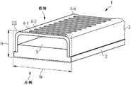
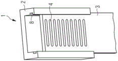
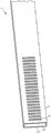
As can be seen in the perspective view of fig. 1, the hybrid busbar 1 which can be used in a busbar system comprises two main components or elements in the exemplary embodiment shown. The hybrid busbar 1 comprises in the embodiment shown a current-carrying rail profile 2 and a contact-receiving rail profile 3. The current-carrying rail profile 2 is adapted to carry a current I having a predetermined high current amplitude a. The contact-receiving rail profile 3 has a plurality of contact openings 4-1, 4-2, … …, 4-n with equal spacing configured for receiving protruding electrical contacts (not shown in fig. 1) of an electrical device to be connected to the busbar system. As can be seen in fig. 1, the current-carrying rail profile 2 and the contact-receiving rail profile 3 are connected to one another to form a hybrid busbar 1 with at least one rectangular cross section. As shown in fig. 1, the rectangular cross section of the hybrid busbar 1 has a rectangular outer envelope cross section CS surrounding the current-carrying rail profile 2 and the at least one contact-receiving rail profile 3.
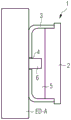
The hybrid busbar 1 can be contacted from the front side by an electrical device ED-a with protruding electrical contacts. These protruding electrical contacts of the electrical device ED can be inserted into the contact openings 4-i for mechanical and electrical contact with the busbar system 1. This is also schematically shown in section CS of fig. 2.
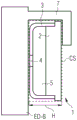
The hybrid busbar 1 of the busbar system shown in fig. 1 can also be engaged from behind by means of hook-shaped mounting locks of other electrical devices ED-B to be connected to the busbar system 1, which is also shown in the section of fig. 3.
Thus, the hybrid busbar 1 shown in fig. 1 can be in contact with two different types of electrical devices ED, namely a first type of electrical device ED-a with protruding electrical contacts and a second type of electrical device ED-B comprising a hook-shaped mounting lock as shown in fig. 3. The hybrid busbar 1 or busbar system shown in fig. 1 can therefore be used for a wide variety of different electrical devices ED and is very flexible to use. Furthermore, the mounting of the electrical device ED to the hybrid busbar 1 shown in fig. 1 can be performed without using any adapter element.
In a possible embodiment, the current-carrying rail profile 2 may comprise an extruded rail profile. The extrusion rail profile 2 can consist of different materials, including copper, aluminum or a two-component material containing copper and aluminum. Furthermore, the contact receiving rail profile 3 can also be made of different materials, including copper, galvanized copper, silvered copper and/or brass. In a possible embodiment, the contact receiving rail profile 3 and the current carrying rail profile 2 may also be at least partially covered with an electrically insulating material, such as a plastic material. This increases the safety of the operator during operation of the bus bar system.
In a possible embodiment, the rectangular outer envelope section CS shown in fig. 1 may comprise a predetermined width W and a predetermined height H. In a possible embodiment, the width W of the rectangular outer envelope section CS is between 12mm and 30 mm. Furthermore, in a possible embodiment, the height H of the rectangular envelope section CS may be 5mm or 10 mm. Thus, in a possible embodiment, the rectangular outer envelope section CS may comprise the following dimensions: 10X 12mm, 10X 20mm, 10X 24mm, 10X 30 mm. In further implementations, the rectangular outer envelope section CS of the hybrid busbar 1 shown in fig. 1 may include the following dimensions: 5X 12mm, 5X 20mm, 5X 24mm, 5X 30 mm. Thus, the hybrid bus 1 shown in fig. 1 is compatible with existing bus systems.
The contact openings 4-i of the contact receiving profile 3 are configured to be equidistant, thereby forming a contact receiving grid. Furthermore, the contact openings 4-i of the contact receiving profile 3 may comprise different shapes, including rectangular contact slots (as shown in fig. 1), square contact openings and circular contact openings. The shape of the contact openings 4-i may vary depending on the use case and the form and shape of the protruding electrical contacts of the corresponding electrical device ED.
In the embodiment shown in fig. 1, the contact receiving rail profile 3 is U-shaped. Between the U-shaped contact receiving rail profile 3 and the current carrying rail profile 2 there is an empty space 5 or cavity which allows insertion of a protruding electrical contact from the electrical device ED through the contact opening 4-i, thereby establishing a mechanical and electrical connection with the hybrid busbar 1 and the corresponding busbar system. The height and dimensions of the cavities 5 for receiving the protruding electrical contacts shown in fig. 2 may vary depending on the electrical device ED used and the form and shape of its protruding electrical contacts. In an alternative embodiment, the contact-receiving rail profile 3 is not U-shaped as shown in fig. 1, but can be formed as a flat current-carrying rail profile 2 as also shown in the embodiments of fig. 10, 11, 12.
There are many possible ways of mechanically connecting the current-carrying rail profile 2 with the contact-receiving rail profile 3. In a possible embodiment, the contact-receiving rail profile 3 can be pressed onto the current-carrying rail profile 2 to form a hybrid busbar 1 with a rectangular outer envelope section CS as shown in fig. 1. In an alternative embodiment, the contact receiving rail profile 3 and the current carrying rail profile 2 may be welded together to form a hybrid busbar 1 with a rectangular outer envelope section CS. In an alternative embodiment, the contact-receiving and current-carrying rail profiles 3, 2 can also be glued together to form the hybrid busbar 1. The contact receiving rail profile 3 and the current carrying rail profile 2 are mechanically attached to each other. In a preferred embodiment, the contact receiving rail profile 3 and the current carrying rail profile 2 of the hybrid busbar 1 are mechanically attached to each other such that they are not easily separated by mechanical forces.
In a possible embodiment, the current carrying rail profile 2 comprises a groove 8 for inserting the contact receiving rail profile 3 into the current carrying rail profile 2 to form the hybrid busbar 1. For example, an exemplary embodiment of a current-carrying rail profile 2 with a groove for inserting a contact-receiving rail profile 3 is shown in fig. 7.
An advantage of the hybrid busbar 1 according to the invention is that the cross-section and the dimensions of the current-carrying rail profile 2 define the current amplitude a that can be carried by the hybrid busbar 1. The majority of the current I flowing through the hybrid busbar 1 is carried by the current-carrying rail profile 2. Only a relatively small part of the current I is carried by the contact-receiving rail profile 3. The size and shape of the current-carrying rail profile 2 thus define the maximum amplitude of the current I that can flow through the hybrid busbar 1 of the busbar system. In a first possible embodiment, the current-carrying rail profile 2 is mechanically connected to the contact-receiving rail profile 3, so that only very high mechanical forces can separate the two elements of the hybrid busbar 1 from one another. In an alternative embodiment, the current-carrying rail profile 2 and the contact-receiving rail profile 3 can be separated from each other, for example by replacing the existing current-carrying rail profile 2 with a new current-carrying rail profile 2' having a different shape or cross section. For example, the hybrid busbar 1 shown in the embodiments of fig. 6, 7, 8 comprises a current-carrying rail profile 2 capable of carrying a predetermined current I with a very high current amplitude a. As shown in the embodiment of fig. 7, the current-carrying rail profile 2 may comprise a recess 8 for inserting at least one contact-receiving rail profile 3. For example, if the current I carried by the current-carrying rail profile 2 shown in fig. 7 is still insufficient for the busbar system 1, the user can replace the current-carrying rail profile 2 shown in fig. 7 with another current-carrying rail profile 2' which has a higher cross section and which is capable of carrying a current I with a higher current amplitude a. For example, the current-carrying rail profile 2 shown in the embodiment of fig. 8 can carry a current I with a higher amplitude a than the embodiment of fig. 7. In the embodiment of fig. 8, the current-carrying rail profile 2 does not have a recess 8 for inserting the contact-receiving rail profile 3. However, in a possible embodiment, the embodiment of fig. 8 may also comprise a groove 8 at the front side, i.e. at its C-shaped front element, for inserting the flat current-carrying rail profile 2 shown in fig. 7. The embodiment with a current-carrying rail profile 2 with at least one recess 8 for inserting one or more contact-receiving rail profiles 3, in particular flat contact-receiving rail profiles, has the advantage that the cross section CS and the current-carrying capacity of the hybrid busbar 1 can be adapted to the respective use case by exchanging the current-carrying rail profile 2 according to the needs of the system 1. In an alternative embodiment, the current-carrying rail profile 2 and the contact-receiving rail profile 3 cannot be separated and form an integrated hybrid busbar 1.
In another possible embodiment of the hybrid busbar 1 shown in fig. 1, the current-carrying rail profile 2 comprises a C-shaped profile and one or more T-shaped profiles. For example, the embodiments shown in fig. 6, 7, 8 represent a current-carrying rail profile 2 having a first C-profile section at the front side of the system, which is integrally formed with one or more T-profile sections.
In yet another possible embodiment of the hybrid busbar 1, the current-carrying rail profile 2 comprises a plurality of T-shaped profile elements stacked on one another forming a mating current cross-section carrying a current I with a predetermined high current amplitude a. A possible implementation of this embodiment of the hybrid busbar 1 is shown in fig. 9.
Fig. 2, 3 show possible mounting alternatives for an electrical device ED to be connected to the hybrid busbar 1 according to the first aspect of the invention. As can be seen in fig. 2, the electrical device ED-a comprises one or more protruding electrical contacts 6 which can be inserted into corresponding equidistant contact openings 4 of the contact receiving rail profile 3. The electrical contacts 6 are configured to establish an electrical connection between the electrical circuit within the electrical device ED-a and the bus bar system. For example, an integrated circuit within the electrical device ED-a may receive the AC mains supply voltage L via the electrical contacts 6. In another possible embodiment, the electrical contacts 6 may be used to supply a DC supply voltage or current to an integrated circuit within the electrical device ED-a. As can be seen in fig. 2, the electrical device ED-a can be easily mounted onto the hybrid busbar 1 of the busbar system from the front side of the hybrid busbar 1 by inserting the protruding electrical contacts 6 of the electrical device ED-a into the corresponding contact openings 4 of the contact receiving rail profiles 3. In a possible embodiment, the electrical device ED-a may be arranged on the front surface of the contact-receiving rail profile 3 and may be pressed against this profile, so that the protruding electrical contact 6 is guided through the contact opening 4 to establish an electrical and mechanical connection. In a possible embodiment, the electrical contacts 6 of the electrical apparatus a may be protected on both sides by a pair of protection ribs (not shown). The protective ribs can on the one hand protect the intermediate electrical contact 6 from mechanical deformation and can additionally provide mechanical support for the electrical device ED-a mounted on the contact-receiving rail profile 3. The number of electrical contacts 6 of an electrical device, such as electrical device ED-a, may vary depending on the use case.
In a possible embodiment, the electrical device ED-a, for example, as shown in fig. 2, can receive one or more supply voltages or currents from the hybrid busbar 1 of the busbar system. In an alternative embodiment, the electrical device ED-a may also comprise a device for feeding electrical power into the busbar system. In a preferred embodiment the hybrid busbar 1 shown in fig. 1, 2, 3 can be used to carry AC or DC supply current. In yet another embodiment, the hybrid bus 1 may also be used to carry communication signals within a bus system. In a possible embodiment, the electrical device ED may comprise an AC interface for the electrical contacts 6 on one side of its housing, which is configured to establish an electrical connection with the hybrid busbar 1 of the busbar system to receive an AC mains supply voltage L, which may be converted by an integrated AC/DC power conversion unit of the electrical device ED-a into a DC supply voltage applied to at least one DC interface of the electrical device ED-a. The electrical contacts 6 of the AC interface may be configured to be inserted into the mating contact openings 4.
In the diagram shown in fig. 3, it can be seen that another type of electrical device ED, which does not comprise a protruding electrical contact 6 on one side of the housing, can also be connected to the hybrid busbar 1 according to the first aspect of the invention. In the schematic shown in fig. 3, the electrical device ED-B comprises a hook-shaped mounting lock 7 which can engage behind the rectangular outer envelope section CS of the hybrid busbar 1 for electrical and/or mechanical connection to the busbar system.
As can be seen from the embodiments shown in fig. 2 and 3, the hybrid busbar 1 according to the first aspect of the invention can be used for different types of electrical devices, i.e. the electrical device ED-a shown in fig. 2 with protruding electrical contacts 6 and/or the electrical device ED comprising e.g. hook-shaped mounting locks 7. In fig. 3, it can be seen that the form of the mounting lock 7 matches the height H of the hybrid busbar 1. In the implementation shown in fig. 3, the electrical device ED-B may comprise an electrical contact 6 on the inner surface of a protruding hook-shaped mounting lock 7 pressed against the surface of the current-carrying rail profile 2. In an alternative embodiment, the electrical device ED-B may also comprise electrical contacts 6 which are pressed against the surface of the current-carrying rail profile 3. In a further possible embodiment, the electrical device ED-B comprises electrical contacts 6 which are pressed onto the surface of the current-carrying rail profile 2 and/or the surface of the contact-receiving rail profile 3.
The electrical devices ED-A, ED-B shown in fig. 2 and 3 can be connected side by side to the same hybrid busbar 1. Depending on the size and length of the hybrid busbar 1, a number of different electrical devices ED-A, ED-B may be connected to the hybrid busbar 1. The connection does not require any adaptation means.
Fig. 4, 5 show two possible embodiments of the hybrid busbar 1 according to the first aspect of the invention. Fig. 4 and 5 show possible embodiments of the hybrid busbar 1 from the front. In both embodiments shown in fig. 4, 5, the contact receiving rail profile 3 is U-shaped and is pressed against the contact receiving rail profile 3. The contact-receiving rail profile 3 of fig. 4 has two parallel projections which allow the contact-receiving rail profile 3 to be pressed against the current-carrying rail profile 2. As can be seen in fig. 4, 5, the contact receiving rail profile 3 comprises a plurality of equidistant or equidistant contact slots 4, which provides the possibility to attach an electrical device ED-4, such as shown in fig. 2, to the busbar system. In the embodiment shown in fig. 5, the current-carrying rail profile 2 has the same outer envelope section CS as the current-carrying profile 2 shown in the embodiment of fig. 4, but a larger physical section for carrying current. Both embodiments of the hybrid busbar 1 shown in fig. 4, 5 are generally used for currents I with a relatively small amplitude a. The embodiment shown in fig. 5 is configured for carrying a current I with a slightly higher amplitude a than the current I that can be carried by the hybrid busbar 1 of fig. 4.
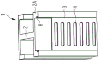
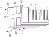
Fig. 6, 7, 8 show further possible embodiments of the hybrid busbar 1 according to the first aspect of the invention. In the embodiment shown in fig. 6, 7, the contact-receiving rail profile 3 has a flat shape. In contrast, the contact receiving rail profile 3 of the embodiment of fig. 8 is U-shaped. In the embodiment shown in fig. 7, the current-carrying rail profile 2 comprises a recess 8 for inserting the flat contact-receiving rail profile 3. In a possible embodiment, the current-carrying rail profile 2 in the embodiment of fig. 7 can be exchanged depending on the use case. The different embodiments of the current-carrying rail profiles 2 shown in fig. 6, 7, 8 each comprise a C-shaped front profile 2A and one or more T-shaped profile sections 2B. As shown in fig. 6, 7, 8, the C-shaped front profile 2A is electrically and mechanically connected to the contact-receiving rail profile 3. In the embodiment of fig. 6, the current-carrying rail profile 2 comprises a C-shaped profile section 2A integrally attached to a T-shaped profile section 2B. The same applies to the embodiment shown in fig. 7. Furthermore, in the embodiment of fig. 7, the C-shaped profile section 2A of the current-carrying rail profile 2 comprises a groove 8 which allows insertion of the flat contact-receiving rail profile 3. In the embodiment of fig. 6, a flat contact-receiving rail profile 3 can be pressed into the cross section of the C-shaped profile section 2A. In the embodiment shown in fig. 8, the hybrid busbar 1 comprises a U-shaped contact receiving rail profile 3 which is pressed into a C-shaped profile section 2A of the current carrying rail profile 2. In the embodiment shown in fig. 8, the current-carrying rail profile 2 comprises more than one T-shaped profile section 2B to increase the cross section of the current-carrying rail profile 2 and to allow currents with higher amplitudes a, for example up to 5000A. Depending on the length of the hook-shaped mounting lock 7 shown in fig. 3, the different T-profile sections 2B allow to connect the electrical device ED-B with different kinds of hook-shaped mounting locks. The first electrical device ED-B with hook-shaped mounting lock 7 can engage from behind a C-shaped profile section 2A with a height H1, or can engage a first T-shaped profile section 2B with a height H2, or a second T-shaped profile section 2B' with a height H3. In a possible embodiment, the electrical device ED-B may even comprise a hook-shaped mounting lock 7 allowing to engage one or more of the C-shaped and T-shaped profile portions from behind, to improve the mechanical stability of the system. The very heavy electrical equipment ED-B therefore comprises a hook-shaped mounting lock 7 that allows not only to engage one rectangular section CS of the hybrid busbar 1, but also to engage a plurality of rectangular outer wrapping sections, i.e. it can engage simultaneously from behind a C-section 2A, T-section 2B and another T-section 2B'.
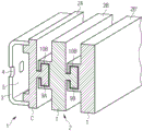
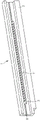
Fig. 9 shows another exemplary embodiment of a hybrid busbar 1 according to the first aspect of the invention. In the exemplary embodiment shown in fig. 9, a plurality of T-shaped profile elements 2B, 2B' are stacked on top of one another to form a mating current cross section for carrying a current I having a predetermined high current amplitude a. In the exemplary implementation shown in fig. 9, the current-carrying rail profile 2 comprises three current-carrying rail profile elements 2A, 2B' which provide a large cross section for high currents I on top of each other. In the exemplary implementation shown, the front C-shaped profile section 2A has a T-shaped projection 9A, which can be inserted into a corresponding receiving section 10B of the T-shaped second current-carrying rail profile element 2B. The T-shaped current-carrying rail profile element 2B itself comprises a T-shaped projection 9B which can be inserted into a corresponding receiving groove 10B 'of the current-carrying rail profile element 2B'. The embodiment shown in fig. 9 has the advantage that the cross section of the current-carrying rail profile 2 can be easily adapted by exchanging different current-carrying rail profile elements and by stacking a plurality of current-carrying rail profiles 2A, 2B', … … until the cross section of the current-carrying rail profile 2 is sufficient for the respective system, depending on the use and the requirements of the busbar system. The hybrid busbar 1 shown in fig. 9 is therefore very flexible and can be adapted to a corresponding busbar system which increases the number of current-carrying rail profile elements or decreases the number of current-carrying rail profiles arranged on top of each other.
In another possible embodiment (not shown), it is also possible to attach the contact-receiving rail profile 3 to the underside of the current-carrying rail profile 2. This embodiment allows to attach electrical devices on both sides to one and the same hybrid busbar 1.
Fig. 10, 11, 12 show further exemplary embodiments of a hybrid busbar 1 according to the first aspect of the invention. In the embodiment shown in fig. 10, 11, the contact-receiving rail profile 3 is flat. In the embodiment shown in fig. 12, the contact receiving rail profile 3 and the current-carrying rail profile 2 are both U-shaped and are pressed into the receiving shape of the current-carrying rail profile 2. In the embodiment shown in fig. 10, the flat contact-receiving rail profile 3 is attached to a corresponding receiving section of the current-carrying rail profile 2, i.e. by means of welding, in particular laser welding. In the embodiment shown in fig. 11, the flat contact-receiving rail profile 3 is inserted into the groove 8 of the current-carrying rail profile 2. The embodiment shown in fig. 11 therefore has the advantage that the contact receiving rail profile 3 can be easily replaced by removing it from the groove 8. In this embodiment, the contact receiving rail profile 3 can be easily replaced. For example, the first contact-receiving rail profile 3 shown in fig. 11 with rectangular contact slots 4 can be replaced by a flat contact-receiving rail profile 3 with differently shaped, equally spaced contact openings 4 (e.g. square contact openings and/or circular contact openings 4). In the embodiments shown in fig. 10, 11, 12, the current-carrying rail profile 2 is configured for carrying a current I having a relatively small current amplitude a.
The current carrying rail profile 2 may comprise a groove 8 along its length, into which groove 8 the contact receiving rail profile 3 may be inserted and attached. Equal-gap contact openings of the current-carrying rail profile 3 can be formed between protruding sections or portions of the contact-receiving rail profile 3. The contact receiving rail profile 3 may comprise a plurality of protruding rectangular blocks defining between them a gap into which a protruding electrical contact 6 of an electrical device ED-a, for example as shown in fig. 2, may be inserted.
Fig. 13 shows another exemplary embodiment of a hybrid busbar 1 according to the first aspect of the invention. As can be seen in fig. 13, the hybrid busbar 1 comprises a current-carrying rail profile 2 with a relatively small cross-section for small currents I and with a recess 8 for inserting a contact-receiving rail profile 3 with a protruding rectangular block 11, the protruding rectangular block 11 defining a gap 12 for receiving a protruding electrical contact of an electrical contact 6 of an electrical device ED-a, such as shown in fig. 2.
In the embodiment shown in fig. 13, the current-carrying rail profile 2 comprises a single groove 8 for receiving a single contact-receiving rail profile 3. In another possible embodiment, the current-carrying rail profile 2 may comprise a plurality of grooves 8 for receiving a corresponding number of contact-receiving rail profiles 3 with projections 11, said projections 11 having receiving gaps 12 for the electrical contacts 6 of the electrical device ED.
Fig. 14 shows another possible embodiment of the hybrid busbar 1 according to the first aspect of the invention. Fig. 14 shows a possible embodiment of a contact receiving rail profile 3 with a plurality of equally spaced contact openings 4. In the embodiment shown in fig. 14, the contact-receiving rail profile 3 is at least partially covered with an electrically insulating material, for example a plastic material M. In the embodiment shown in fig. 14, a first part of the contact-receiving rail profile 3 is not covered by an electrically insulating layer M and another part of the contact-receiving rail profile 3 is completely covered by an electrically insulating layer made of an electrically insulating material (for example, a plastic material M). An electrically insulating layer may be applied to the contact-receiving rail profile 3. For example, equal-gap contact openings or slots 4 are punched into the contact receiving rail profiles 3 of the hybrid busbar 1. Fig. 14 shows the contact-receiving rail profile 3 with a covering insulation material M on the front side. Insulation may also be provided by a separate insulating element attached to the hybrid busbar 1.
The contact-receiving rail profile 3 can be completely insulated in at least one section by a surrounding electrically insulating layer made of an electrically insulating material M. It is also possible to cover the contact-receiving rail profile 3 with an electrically insulating layer made of insulating material M only on the front side, but not on the rear side. In the embodiment shown in fig. 14, the contact receiving rail profile 3 is U-shaped. In a further possible embodiment, the contact-receiving rail profile 3 can also be formed flat, wherein the front side and/or the rear side of the flat contact-receiving rail profile 3 is covered with an electrically insulating layer made of an electrically insulating and fire-resistant material M.
Fig. 15 shows a further possible embodiment of the hybrid busbar 1 according to the first aspect of the invention. In the embodiment shown, the hybrid busbar 1 is produced by roll forming having its shape, wherein the two ends of the roll formed shape are welded together to form a blank space or contact receiving cavity 5 for the protruding electrical contact 6. An equidistant contact opening 4 is provided on the front side of the hybrid busbar 1. Thus, in the embodiment shown in fig. 15, the hybrid busbar 1 comprises a contact receiving rail profile 3 formed by the front side and a current carrying rail profile 2 formed by the rear side of the roll-formed element.
Fig. 16 shows a possible exemplary embodiment of an electrical insulation module or insulation unit for a busbar system according to a further aspect of the invention. In the embodiment shown, the electrically insulating unit 13 is adapted to receive three hybrid busbars 1-1, 1-2, 1-3 according to the first aspect of the invention. In the embodiment shown in fig. 16, the three hybrid busbars 1-1, 1-2, 1-3 each comprise a current-carrying rail profile 2-1, 2-2, 2-3 and an associated contact-receiving rail profile 3-1-, 3-2, 3-3. The electrically insulating distribution switchboard 13 comprises a front part 14 having a corresponding number of rows 15-1, 15-2, 15-3 of equal-gap contact openings 16, which are aligned with the equal-gap contact openings 4 of the contact receiving rail profiles 3-i of the hybrid busbars 1-1, 1-2, 1-3. In the exemplary embodiment shown in fig. 16, the electrically insulating distribution switchboard unit 13 comprises three rows 15-1, 15-2, 15-3, wherein each row comprises a plurality of equally spaced contact openings 16 aligned with the equally spaced contact openings 4 of the contact receiving rail profiles 3-i of the hybrid busbar 1-i. The insulating unit 13 shown in fig. 16 is made of an electrically insulating material and can effectively protect a user from high currents I and/or high voltages. Electrical devices ED, such as the electrical device ED-a shown in fig. 2, can be attached to the electrical insulation module 13 by first inserting their electrical contacts 6 through the contact openings 16 of the front cover or front portion 14 of the insulation module 13 and then through the aligned contact openings 4 of the contact receiving rail profiles 3-i located directly below the contact openings 16.
Fig. 17 shows a further view of an electrically insulating distribution switchboard unit 13 according to the second aspect of the present invention. In the embodiment shown in fig. 17, the different rows 15-i of equally spaced contact openings 16 do not cover the entire front cover of the insulating unit 13. The number of hybrid busbars 1 wrapped by the electrically insulating units 13 may vary depending on the system and the use. In the embodiment shown in fig. 10, 17, the electrically insulating unit 13 is configured to receive and encase three hybrid bus bars 1 according to the first aspect of the invention.
The rectangular outer envelope section CS of the hybrid busbar 1 is formed such that their dimensions (i.e. height H and width W) correspond to those of a conventional busbar. Thus, the hybrid busbar 1 can be easily used to replace an existing conventional busbar 1 of a busbar system. In a possible embodiment, the bus bar system may even comprise a combination of a common conventional bus bar and the hybrid bus bar 1 according to the first aspect of the invention.
Fig. 18 schematically shows the internal structure of the electrical insulation unit 13 according to the second aspect of the present invention. In the embodiment shown in fig. 18, the electrically insulating unit 13 may comprise an element 17 for carrying the hybrid busbar 1-1, 1-2, 1-3 consisting of the current-carrying rail profile 2-1, 2-2, 2-3 and the attached contact-receiving rail profile 3-1, 3-2, 3-3, respectively. The different flat contact-receiving rail profiles 3-1, 3-2, 3-3 comprise at least partially a section with a plurality of equally spaced contact openings 4 as shown in fig. 18. The busbar carrying element 17 may for example be attached to a mounting plate of an electrical control cabinet. The clamping bracket 18 shown in the embodiment of fig. 18 can be used to contact the hybrid busbar 1. These clamping brackets 18 are designed to be inserted through the contact openings 16 of the electrically insulating unit 13 and to engage with the equally spaced contact openings 4 of the contact receiving rail profiles 3-i of the hybrid busbar 1. The electrically insulating unit 13 may also internally comprise engaging transverse rails 21-1, 21-2, which may be used for mechanical engaging elements of an electrical device ED attached to the unit 13, in particular a mechanically fixed electrical device ED having a high weight. The electrically insulating unit 13 may completely surround the included hybrid busbar 1. In an alternative embodiment, the electrically insulating unit 13 comprises only an electrically insulating front portion 14 having a plurality of rows 15 of contact openings 16 each comprising a plurality of equal gaps. In a possible embodiment, the electrically insulating unit 13 is adapted to receive the hybrid busbar 1 according to the first aspect of the invention and, at the same time, a conventional busbar having a corresponding cross section. When mounted in the unit 13, the busbars extend generally in a horizontal direction. The electrical devices may also be connected by a cable 20 having electrical contacts 19 inserted through the slot 16 into the slot 4.
Fig. 19A, 19B, 19C show hook-shaped mounting locks 7A, 7B engaging the current-carrying rail profile 2 of the hybrid busbar 1 from behind. In the illustrated example of fig. 19A, 19B, the mounting locks 7A, 7B form part of a clamping unit 22 comprising screws or threaded pins for attaching the current carrying rail 23 to the hybrid busbar 1. Fig. 19A shows the insertion of the electrical contact 6 of the electrical device into the slot 4 of the contact receiving rail profile 3 of the hybrid busbar 1. The electrical contact 19 of the cable 20 can also be inserted into this groove 4 of the contact-receiving rail profile 3.
In fig. 19C it can be seen that the hybrid busbar 1 can also be contacted by a clamp element 28 with a spring element 29, which spring element 29 is adapted to press the current-carrying rail 30 against the surface of the hybrid busbar 1, i.e. against the contact-receiving rail profile 3 shown in fig. 19C, or against the current-carrying rail profile 2, to establish a mechanical and electrical connection with the hybrid busbar 1.
Fig. 20 shows an embodiment in which the contact-receiving rail profile 3 is connected to the current-carrying rail profile 2 by means of a mechanical connecting element 24 with an intermediate spacing element 25 of electrically conductive material positioned between the contact-receiving profile 3 and the current-carrying rail profile 2. The mechanical connection element 24 comprises a first part 24A and a second part 24B having a receiving recess for receiving the hybrid busbar 1. The receiving groove has a height H and a width W defining a rectangular cross-section corresponding to the boundary geometry of the rectangular cross-section CS with the hybrid busbar 1. Height H of spacing element 25dDepending on the height h of the contact receiving rail profile 3 and the current-carrying rail profile 2, respectively3、h2(hd+h2+h3=H)。
The intermediate spacing element 25 may be a separate exchangeable element or be attached to the contact-receiving rail profile 3 or the current-carrying rail profile 2. Screws 26, 27 may be used to fix the upper part 24A to the lower part 24B of the mechanical connection element 24, which may press the contact-receiving rail profile 3 slightly against the current-carrying rail profile 2 via the intermediate spacing element 25. In alternative embodiments, the contact receiving rail profile 3 is fixed to the current-carrying rail profile 2 by means of other mechanical connection means, including screws, bolts or rivet elements.
In another possible embodiment, the hybrid busbar 1 may comprise, in addition to the contact-receiving and current-carrying rail profiles 3, 2, data-transmission rail profile elements which extend parallel with respect to the contact-receiving and current-carrying rail profiles 3, 2. The data transmission rail profile can be used for data transmission of data signals between electrical devices ED having contacts 6 inserted into the slots 4 of the contact receiving rail profile 3 and/or through electrical devices ED engaging with the current carrying rail profile 2 by means of the hook lock 7. In an alternative embodiment, the communication of the data transfer can take place by the PLC via the hybrid busbar 1 (i.e. via the current-carrying rail profile 2 and/or via the contact-receiving rail profile 3).
The different embodiments of the hybrid busbar 1 according to the invention shown in the different figures can be combined with one another.
Reference numerals
1 hybrid busbar
2 Current-carrying guide rail section bar
3 contact receiving guide rail section bar
4 contact opening
5 contact receiving cavity
6 electric contact
7. 7A, 7B installation lock
8 grooves
9A, 9B protrusions
10A, 10B receiving recess
11 protruding block
12 contact receiving gap
13 distribution switch board
14 front cover
15 contact slot row
16 grooves
17 bus bar carrying element
18 clamping bracket
19 electric contact
20 electric cable
21 transverse guide rail
22 clamping unit
23 current carrying rail
24 mechanical connecting element
25 intermediate member
26. 27 screw
28 clamping element
29 spring element
30 current carrying rail
Claims (20)
1. Hybrid busbar (1) for connecting different types of electrical devices (ED-a, ED-B) forming a front side of a busbar system, the hybrid busbar (1) comprising:
-a rear current-carrying rail profile (2) adapted to carry a current having a predetermined high current amplitude; and
-at least one front side contact receiving rail profile (3) having a plurality of contact openings (4) with equal clearance configured for receiving protruding electrical contacts of a first type of electrical device (ED-A) to be connected to a busbar system,
wherein an electrical device (ED-A) of a first type can be arranged on a front surface of the front side contact receiving rail profile (3) and pressed against the front side contact receiving rail profile (3) such that a protruding electrical contact (6) is guided through the contact opening (4) to establish an electrical connection with the busbar system,
wherein a rear current-carrying rail profile (2) and a front contact-receiving rail profile (3) are connected to each other to form the hybrid busbar (1), which can be engaged from behind by means of a hook-shaped mounting lock (7) of a second type of electrical device (ED-B) for electrical and mechanical connection with the busbar system.
2. Hybrid busbar according to claim 1, wherein the hybrid busbar (1) comprises at least one boundary geometry with a rectangular cross section CS which is engageable by a hook-shaped mounting lock (7) of an electrical device (ED-B) to be connected to the busbar system.
3. Hybrid busbar according to claim 1, wherein the current-carrying rail profile (2) comprises a rail profile made of copper, aluminum or a two-component material comprising copper and aluminum.
4. Hybrid busbar according to claim 1, wherein the contact receiving rail profile (3) is made of copper, tin-plated copper, silver-plated copper or brass.
5. The hybrid busbar of claim 2, wherein the boundary geometry with rectangular cross-section CS has a width W between 12mm and 30mm and a height H of 5mm or 10 mm.
6. Hybrid busbar according to claim 1, wherein the contact openings (4) of the contact receiving rail profiles (3) comprise different shapes, including rectangular contact slots, square contact openings and circular contact openings.
7. Hybrid busbar according to claim 1, wherein the contact receiving rail profile (3) is U-shaped or flat.
8. Hybrid busbar according to claim 1, wherein the contact receiving rail profile (3) is connected to the current carrying rail profile (2) by a press fit connection to form a hybrid busbar (1) providing a boundary geometry with a rectangular cross section CS.
9. Hybrid busbar according to claim 1, wherein the contact receiving rail profile (3) is connected to the current carrying rail profile (2) by a material bond connection to form a hybrid busbar (1) providing a boundary geometry with a rectangular cross section CS.
10. Hybrid busbar according to claim 1, wherein the contact receiving rail profile (3) is connected to the current carrying rail profile (2) by one or more mechanical connection elements.
11. Hybrid busbar according to claim 1, wherein the current carrying rail profile (2) comprises at least one groove (8) for inserting the contact receiving rail profile (3) into the current carrying rail profile (2) to form the hybrid busbar (1).
12. Hybrid busbar according to claim 1, wherein the contact receiving rail profile (3) and/or the current carrying rail profile (2) are at least partially covered with an electrically insulating layer.
13. The hybrid busbar of claim 12, wherein the electrically insulating layer comprises a plastic material.
14. Hybrid busbar according to claim 1, wherein the cross section CS of the current-carrying rail profile (2) is configured to carry an alternating or direct current with a predetermined high current amplitude of up to 5000A.
15. Hybrid busbar according to claim 1, wherein the current-carrying rail profile (2) comprises a C-shaped profile (2A) and one or more T-shaped profiles (2B).
16. Hybrid busbar according to claim 15, wherein the current-carrying rail profile (2) comprises a plurality of T-shaped profiles (2B) which, stacked on one another, form a mating current section for carrying a current having a predetermined high current amplitude.
17. Hybrid busbar according to claim 1, further comprising busbar data transmission elements attached to current-carrying rail profiles (2) and/or to contact-receiving rail profiles (3) for data transfer of data and connectable through Electrical Devices (ED) for exchanging data between the Electrical Devices (ED) and/or external data processing devices.
18. Hybrid busbar according to claim 2, wherein the rectangular section CS is a rectangular enveloping section which can be engaged by a hook-shaped mounting lock (7) of an electrical device of the second type (ED-B) for connection to the busbar system.
19. Hybrid busbar according to claim 18, wherein the electrical device of the second type (ED-B) comprises electrical contacts which press against the surface of the rear current-carrying rail profile (2) or the surface of the front contact-receiving rail profile (3) when the rectangular outer envelope section CS of the hybrid busbar (1) is engaged by the hook-shaped mounting lock (7) of the electrical device of the second type (ED-B).
20. An electrical insulation unit (13) for a busbar system, comprising a front portion (14) with equidistant contact openings (16) which are aligned with the equidistant contact openings (4) of a contact receiving rail profile (3) wrapped by the electrical insulation unit (13) forming part of a hybrid busbar (1) according to any one of claims 1 to 17.
Applications Claiming Priority (3)
| Application Number | Priority Date | Filing Date | Title |
|---|---|---|---|
| EP18162101.2 | 2018-03-15 | ||
| EP18162101.2A EP3540872A1 (en) | 2018-03-15 | 2018-03-15 | A hybrid busbar for a busbar system |
| PCT/EP2019/055981 WO2019175087A1 (en) | 2018-03-15 | 2019-03-11 | A hybrid busbar for a busbar system |
Publications (2)
| Publication Number | Publication Date |
|---|---|
| CN112005450A CN112005450A (en) | 2020-11-27 |
| CN112005450B true CN112005450B (en) | 2022-02-18 |
Family
ID=61683702
Family Applications (2)
| Application Number | Title | Priority Date | Filing Date |
|---|---|---|---|
| CN201980019487.9A Active CN111971859B (en) | 2018-03-15 | 2019-02-21 | Touch protection bus system |
| CN201980019559.XA Active CN112005450B (en) | 2018-03-15 | 2019-03-11 | Hybrid bus for bus system |
Family Applications Before (1)
| Application Number | Title | Priority Date | Filing Date |
|---|---|---|---|
| CN201980019487.9A Active CN111971859B (en) | 2018-03-15 | 2019-02-21 | Touch protection bus system |
Country Status (7)
| Country | Link |
|---|---|
| US (2) | US11888272B2 (en) |
| EP (2) | EP3540872A1 (en) |
| CN (2) | CN111971859B (en) |
| BR (2) | BR112020018611A2 (en) |
| ES (1) | ES2936621T3 (en) |
| PL (1) | PL3766146T3 (en) |
| WO (2) | WO2019174886A1 (en) |
Families Citing this family (4)
| Publication number | Priority date | Publication date | Assignee | Title |
|---|---|---|---|---|
| EP3540872A1 (en) * | 2018-03-15 | 2019-09-18 | Wöhner Besitz GmbH | A hybrid busbar for a busbar system |
| GB2574727A (en) * | 2018-06-13 | 2019-12-18 | Eaton Intelligent Power Ltd | Electrical panelboard and plug-in device for such a panelboard with improved electrical insulation and modularity |
| PL3926774T3 (en) | 2020-06-19 | 2023-03-06 | Wöhner Besitz Gmbh | Busbar board |
| EP3926770A1 (en) | 2020-06-19 | 2021-12-22 | Wöhner Besitz GmbH | Elongated busbar board |
Citations (10)
| Publication number | Priority date | Publication date | Assignee | Title |
|---|---|---|---|---|
| DE4109040A1 (en) * | 1991-03-15 | 1992-09-17 | Wago Verwaltungs Gmbh | Domestic electrical distributor unit - has electrical leads inserted in two opposing directions in alternation |
| CN101553959A (en) * | 2006-10-16 | 2009-10-07 | 克尼尔有限公司 | Power rail system |
| DE102008033159B3 (en) * | 2008-07-15 | 2010-04-08 | Siemens Aktiengesellschaft | Electrical current- or potential busbar arrangement for use in automation device, has electrically isolated support covering sides of potential busbars, and contact-in plugs formed with sharp-edges to pierce into support |
| CN101796700A (en) * | 2007-08-06 | 2010-08-04 | Abb公司 | panelboard |
| CN102474087A (en) * | 2009-07-10 | 2012-05-23 | 西门子公司 | Modular Busbar |
| CN202759120U (en) * | 2012-07-18 | 2013-02-27 | 中兴通讯股份有限公司 | Busbar |
| CN103444000A (en) * | 2011-04-13 | 2013-12-11 | 泛达公司 | Ground bar assembly comprising a mounting bracket and/or a conductor block |
| CN203589401U (en) * | 2013-12-04 | 2014-05-07 | 张伟明 | Mobile power supply socket combination module |
| EP3136524A1 (en) * | 2015-08-28 | 2017-03-01 | LISI AUTOMOTIVE Mecano GmbH | Grounding nuts chain |
| WO2017198642A1 (en) * | 2016-05-17 | 2017-11-23 | Wöhner GmbH & Co. KG Elektrotechnische Systeme | Device for a busbar system |
Family Cites Families (25)
| Publication number | Priority date | Publication date | Assignee | Title |
|---|---|---|---|---|
| US3727171A (en) * | 1971-07-23 | 1973-04-10 | Westinghouse Canada Ltd | Bus connector assembly |
| US4699445A (en) * | 1986-07-28 | 1987-10-13 | Amp Incorporated | Electrical terminal assembly for thermistors |
| DE3817440A1 (en) * | 1988-05-21 | 1989-11-30 | Vev Verwaltung Entwicklung Ver | Bus-bar |
| US20070111592A1 (en) * | 2005-11-15 | 2007-05-17 | Smith Leslie F | Modular plug strip |
| DE102005060586B4 (en) | 2005-12-17 | 2008-02-14 | Abb Patent Gmbh | installation distribution |
| DE102007027918B4 (en) | 2007-06-18 | 2010-07-08 | Siemens Ag | Power rail for power and data supply of electrical devices |
| JP5339357B2 (en) * | 2009-05-01 | 2013-11-13 | 河村電器産業株式会社 | Residential distribution board |
| GB0910199D0 (en) * | 2009-06-15 | 2009-07-29 | 3M Innovative Properties Co | Symmetrical termination strip for a telecommunications moduel |
| FR2951031B1 (en) * | 2009-10-06 | 2011-10-28 | Schneider Electric Ind Sas | FUNCTIONAL UNIT FOR LOW VOLTAGE CHART WITH TEST POSITION |
| US20130225012A1 (en) * | 2010-07-15 | 2013-08-29 | Lip-Sing Leng | Electrical power distribution track system |
| US8585422B2 (en) * | 2011-04-15 | 2013-11-19 | Rockwell Automation Technologies, Inc. | System for connecting motor drives |
| DE102011085517A1 (en) * | 2011-10-31 | 2013-05-02 | Siemens Aktiengesellschaft | Coupling for rail system used as electrical distribution system, has bus-bars that are designed to pivot about a specific end between two positions, for closing and opening electrical connection between coupling points, respectively |
| US20150047876A1 (en) | 2012-03-20 | 2015-02-19 | Albus Industries Pty Ltd | Busbar |
| DE102012206597B4 (en) * | 2012-04-20 | 2015-02-26 | Wöhner GmbH & Co. KG Elektrotechnische Systeme | Busbar adapter |
| ES2638939T3 (en) | 2013-10-18 | 2017-10-24 | Wöhner GmbH & Co. KG Elektrotechnische Systeme | Contact protection system for current busbars |
| CN105900181B (en) | 2013-12-03 | 2018-05-04 | 施耐德电气It公司 | System for making high current busbar insulate |
| EP3076504B1 (en) * | 2015-03-31 | 2018-07-04 | Wöhner GmbH & Co. KG Elektrotechnische Systeme | Adapter device for a busbar system |
| WO2016168854A1 (en) | 2015-04-17 | 2016-10-20 | Traxxas Lp | Steering stabilizing apparatus for a model vehicle |
| CN106298713A (en) * | 2015-06-09 | 2017-01-04 | 台达电子工业股份有限公司 | The pin that a kind of power model connected vertically and stacking thereof connect |
| CN104966964A (en) * | 2015-07-14 | 2015-10-07 | 林健生 | Wire slot with conductors and matching socket panel thereof |
| DE102015213744A1 (en) * | 2015-07-21 | 2017-01-26 | Ellenberger & Poensgen Gmbh | power distribution |
| DE102016107565A1 (en) * | 2016-04-22 | 2017-10-26 | Rittal Gmbh & Co. Kg | Arrangement for the contact-safe contacting of a busbar system |
| US10750628B2 (en) * | 2016-05-06 | 2020-08-18 | Cummins Inc. | Adapters for electronic control unit |
| CN206313243U (en) * | 2017-04-12 | 2017-07-07 | 深圳市康奈特电子有限公司 | A kind of hot plug busbar connection system |
| EP3540872A1 (en) * | 2018-03-15 | 2019-09-18 | Wöhner Besitz GmbH | A hybrid busbar for a busbar system |
-
2018
- 2018-03-15 EP EP18162101.2A patent/EP3540872A1/en active Pending
-
2019
- 2019-02-21 BR BR112020018611-2A patent/BR112020018611A2/en active Search and Examination
- 2019-02-21 PL PL19705204.6T patent/PL3766146T3/en unknown
- 2019-02-21 WO PCT/EP2019/054343 patent/WO2019174886A1/en active Application Filing
- 2019-02-21 ES ES19705204T patent/ES2936621T3/en active Active
- 2019-02-21 CN CN201980019487.9A patent/CN111971859B/en active Active
- 2019-02-21 EP EP19705204.6A patent/EP3766146B1/en active Active
- 2019-02-21 US US16/977,295 patent/US11888272B2/en active Active
- 2019-03-11 WO PCT/EP2019/055981 patent/WO2019175087A1/en active Application Filing
- 2019-03-11 US US15/733,558 patent/US11139622B2/en active Active
- 2019-03-11 BR BR112020017035-6A patent/BR112020017035A2/en unknown
- 2019-03-11 CN CN201980019559.XA patent/CN112005450B/en active Active
Patent Citations (10)
| Publication number | Priority date | Publication date | Assignee | Title |
|---|---|---|---|---|
| DE4109040A1 (en) * | 1991-03-15 | 1992-09-17 | Wago Verwaltungs Gmbh | Domestic electrical distributor unit - has electrical leads inserted in two opposing directions in alternation |
| CN101553959A (en) * | 2006-10-16 | 2009-10-07 | 克尼尔有限公司 | Power rail system |
| CN101796700A (en) * | 2007-08-06 | 2010-08-04 | Abb公司 | panelboard |
| DE102008033159B3 (en) * | 2008-07-15 | 2010-04-08 | Siemens Aktiengesellschaft | Electrical current- or potential busbar arrangement for use in automation device, has electrically isolated support covering sides of potential busbars, and contact-in plugs formed with sharp-edges to pierce into support |
| CN102474087A (en) * | 2009-07-10 | 2012-05-23 | 西门子公司 | Modular Busbar |
| CN103444000A (en) * | 2011-04-13 | 2013-12-11 | 泛达公司 | Ground bar assembly comprising a mounting bracket and/or a conductor block |
| CN202759120U (en) * | 2012-07-18 | 2013-02-27 | 中兴通讯股份有限公司 | Busbar |
| CN203589401U (en) * | 2013-12-04 | 2014-05-07 | 张伟明 | Mobile power supply socket combination module |
| EP3136524A1 (en) * | 2015-08-28 | 2017-03-01 | LISI AUTOMOTIVE Mecano GmbH | Grounding nuts chain |
| WO2017198642A1 (en) * | 2016-05-17 | 2017-11-23 | Wöhner GmbH & Co. KG Elektrotechnische Systeme | Device for a busbar system |
Also Published As
| Publication number | Publication date |
|---|---|
| US20200412074A1 (en) | 2020-12-31 |
| WO2019174886A1 (en) | 2019-09-19 |
| WO2019175087A1 (en) | 2019-09-19 |
| BR112020018611A2 (en) | 2020-12-29 |
| EP3766146B1 (en) | 2022-12-14 |
| CN112005450A (en) | 2020-11-27 |
| CN111971859B (en) | 2022-09-06 |
| BR112020017035A2 (en) | 2021-03-23 |
| EP3766146A1 (en) | 2021-01-20 |
| US11888272B2 (en) | 2024-01-30 |
| CN111971859A (en) | 2020-11-20 |
| US20210006047A1 (en) | 2021-01-07 |
| PL3766146T3 (en) | 2023-04-03 |
| US11139622B2 (en) | 2021-10-05 |
| ES2936621T3 (en) | 2023-03-21 |
| EP3540872A1 (en) | 2019-09-18 |
Similar Documents
| Publication | Publication Date | Title |
|---|---|---|
| CN112005450B (en) | Hybrid bus for bus system | |
| CN105474469B (en) | Contact element for the bell and spigot frame for being especially external routes bus system | |
| US10700464B2 (en) | Device for a busbar system | |
| US11109504B2 (en) | Power distribution unit with interior busbars | |
| EP2509114A2 (en) | Photovoltaic mounting system with grounding bars and method of installing same | |
| JP5678240B2 (en) | Terminal unit having composite / distribution busbar assembly with fuse | |
| EP2181487B1 (en) | Panelboard | |
| HU223704B1 (en) | Upgradable functional feeder unit of a low-voltage electrical cubicle | |
| EP2858229B1 (en) | Apparatus for Connecting a Shared DC Bus Link | |
| CN109950795B (en) | Current distribution device in an electrical panel or electrical switchgear | |
| CN111081501A (en) | Device for supplying power and electrically connecting a contactor to a set of modular electrical units | |
| KR200393273Y1 (en) | Connector for clamping vertical busber of switch board | |
| CN108604745B (en) | Loop bridge for circulating multiple electrical signals therethrough | |
| FI72622C (en) | STROEMANSLUTNINGSANORDNING FOER AOSTADKOMMANDE AV ELEKTRISK ANSLUTNING MELLAN LEDNINGAR. | |
| CN209748146U (en) | Rail mounted minibus distribution equipment | |
| CN210607136U (en) | Integrated bus system | |
| KR20080103810A (en) | Bus-bar connector and distribution-switchboard | |
| PL205243B1 (en) | Electric switchgear for electric equipment mounted in parallel rows on distribution board or inside switchbox and distribution board or electric switchbox | |
| CN111384614B (en) | Terminal assembly and power connector | |
| CN210744370U (en) | Terminal interface device for distribution module and rail type terminal bus trunk body | |
| EP4102665A1 (en) | Electrical busway assembly | |
| CN210326386U (en) | Bus bar | |
| EP3060032B1 (en) | Power terminal | |
| HU220263B (en) | Device for connecting electrical-installation apparatuses | |
| CN110582907B (en) | Multi-feed bus bar system |
Legal Events
| Date | Code | Title | Description |
|---|---|---|---|
| PB01 | Publication | ||
| PB01 | Publication | ||
| SE01 | Entry into force of request for substantive examination | ||
| SE01 | Entry into force of request for substantive examination | ||
| GR01 | Patent grant | ||
| GR01 | Patent grant |