CN111981194A - Anti-leakage self-sealing valve - Google Patents
Anti-leakage self-sealing valve Download PDFInfo
- Publication number
- CN111981194A CN111981194A CN202010889558.5A CN202010889558A CN111981194A CN 111981194 A CN111981194 A CN 111981194A CN 202010889558 A CN202010889558 A CN 202010889558A CN 111981194 A CN111981194 A CN 111981194A
- Authority
- CN
- China
- Prior art keywords
- rod
- valve
- sealing
- sealing ring
- groove
- Prior art date
- Legal status (The legal status is an assumption and is not a legal conclusion. Google has not performed a legal analysis and makes no representation as to the accuracy of the status listed.)
- Withdrawn
Links
- 238000007789 sealing Methods 0.000 title claims abstract description 91
- 230000007246 mechanism Effects 0.000 claims abstract description 19
- 210000004907 gland Anatomy 0.000 claims abstract description 13
- 238000005096 rolling process Methods 0.000 claims description 36
- 230000006835 compression Effects 0.000 claims description 22
- 238000007906 compression Methods 0.000 claims description 22
- 241000283216 Phocidae Species 0.000 claims description 12
- 230000006978 adaptation Effects 0.000 claims description 2
- 230000008878 coupling Effects 0.000 claims description 2
- 238000010168 coupling process Methods 0.000 claims description 2
- 238000005859 coupling reaction Methods 0.000 claims description 2
- 238000000926 separation method Methods 0.000 claims description 2
- 230000002035 prolonged effect Effects 0.000 abstract description 2
- XLYOFNOQVPJJNP-UHFFFAOYSA-N water Substances O XLYOFNOQVPJJNP-UHFFFAOYSA-N 0.000 description 8
- 230000000694 effects Effects 0.000 description 3
- 239000012530 fluid Substances 0.000 description 3
- 230000004048 modification Effects 0.000 description 2
- 238000012986 modification Methods 0.000 description 2
- 238000010586 diagram Methods 0.000 description 1
- 230000006872 improvement Effects 0.000 description 1
- 238000000034 method Methods 0.000 description 1
- 230000002093 peripheral effect Effects 0.000 description 1
Images


Classifications
-
- F—MECHANICAL ENGINEERING; LIGHTING; HEATING; WEAPONS; BLASTING
- F16—ENGINEERING ELEMENTS AND UNITS; GENERAL MEASURES FOR PRODUCING AND MAINTAINING EFFECTIVE FUNCTIONING OF MACHINES OR INSTALLATIONS; THERMAL INSULATION IN GENERAL
- F16K—VALVES; TAPS; COCKS; ACTUATING-FLOATS; DEVICES FOR VENTING OR AERATING
- F16K41/00—Spindle sealings
- F16K41/02—Spindle sealings with stuffing-box ; Sealing rings
- F16K41/04—Spindle sealings with stuffing-box ; Sealing rings with at least one ring of rubber or like material between spindle and housing
Landscapes
- Engineering & Computer Science (AREA)
- General Engineering & Computer Science (AREA)
- Mechanical Engineering (AREA)
- Mechanically-Actuated Valves (AREA)
Abstract
The invention discloses an anti-leakage self-sealing valve which comprises a valve body, a valve cover, a gland, a valve rod, a limiting block, a lower sealing ring, a valve plate, a hand wheel, a self-sealing mechanism and a support, wherein the support is pressed between the valve cover and the valve body, the valve rod comprises an upper valve rod and a threaded rod, the upper valve rod can move up and down relative to the valve cover, the threaded rod is rotatably arranged on the support and is in threaded connection with the valve plate, an annular limiting groove is formed in a main rod body of the upper valve rod, an L-shaped limiting groove is formed in the bottom of the annular limiting groove, a driving block is connected to the lower end of the main rod body, a driving groove is formed in the top end of the threaded rod, the lower sealing ring is arranged in a sealing groove in the lower portion of the valve cover, the self-sealing mechanism. When the lower sealing ring is used daily, the lower sealing ring is in a natural state, so that the lower sealing ring is prevented from being in a compressed state for a long time, and the service life of the lower sealing ring is prolonged.
Description
Technical Field
The invention relates to the technical field of valves, in particular to an anti-leakage self-sealing valve.
Background
The valve is a control component in a fluid conveying system, has the functions of diversion, cut-off, throttling, non-return and the like, and common cut-off valves comprise gate valves, ball valves, stop valves, butterfly valves and the like.
The published patent CN203628011U discloses a fluid control valve, which provides an anti-leakage self-sealing valve with good sealing effect and capable of replacing a sealing ring under the condition of not stopping water pressure, comprising a valve body, a valve cover, a gland, a valve plate, a valve rod, an opening device, a reverse taper sealing ring and a pressing ring, wherein the valve cover is arranged above the valve body, the gland is detachably arranged above the valve cover, the valve body is provided with a water inlet and a water outlet which are communicated with a medium fluid, the valve plate is arranged between the water inlet and the water outlet and can be lifted up and down, one end of the valve rod passes through the gland and the valve cover to be in threaded connection with the valve plate, the opening device is arranged at the free end of the valve rod, at least two upper sealing rings are arranged between the gland and the valve rod, a limiting ring which limits the valve rod to move axially is arranged between the upper end of the valve rod and the, the compressing ring is sleeved on the upper part of the valve plate outside the lower part of the valve rod and can lift along with the vertical lifting of the valve plate, and after the valve is completely opened, the compressing ring is compressed on the inverted cone sealing ring, so that the upper sealing ring can be replaced by the water continuously. But in the in-service use in-process discovery, when the valve is in the open mode often, the back taper sealing washer is also compressed for a long time often for the back taper sealing washer is very easily damaged.
Disclosure of Invention
In view of this, the present invention provides an anti-leaking self-sealing valve to solve the above technical problems.
In order to achieve the purpose, the invention provides the following technical scheme: the utility model provides a prevent outer hourglass self sealss valve, includes valve body, valve gap, gland, valve rod, stopper, lower seal circle, valve plate and hand wheel, still includes self sealss mechanism and support, the support is pressed fitting in between valve gap and the valve body, the valve rod includes valve rod and sets up the threaded rod of going up the valve rod below, it can move about from top to bottom to go up the valve rod, the threaded rod rotates to set up on the support, just the threaded rod with valve plate threaded connection, be provided with on the main body of rod with stopper matched with annular spacing groove, the bottom of annular spacing groove be provided with stopper matched with L shape spacing groove, the lower extreme of the main body of rod is connected and is provided with the drive block, the top of threaded rod be provided with the drive groove of drive block looks adaptation, when the stopper card is gone into in the horizontal extension portion of L shape spacing groove, the drive block with the drive groove separation, the lower seal circle is installed in the seal groove of valve gap lower part, the interior week of lower seal circle support press on the main pole body, self sealss mechanism is including helping push bench and a plurality of elasticity push rod, help push bench rigid coupling is in on the main pole body, a plurality of elasticity push rod encircles the main pole body interval sets up, the lower extreme of elasticity push rod supports to press on the help push bench, the upper end of elasticity push rod support press on the lower seal circle.
Further, the interval is provided with first lip and second lip on the inner periphery of lower seal circle, first lip with the second lip all supports to press in the periphery of the main pole body, be provided with the third lip on the outer peripheral part on lower seal circle upper portion, the third lip is pressed fitting in the extension inslot at seal groove top.
Furthermore, the top of the elastic push rod is provided with a pressing plate part which is pressed against the lower sealing ring.
Furthermore, the bottom of the elastic push rod is provided with a universal ball which can roll on the boosting platform.
Furthermore, the elastic push rod comprises an upper rod sleeve, a lower push rod with the upper end movably arranged in the inner hole of the upper rod sleeve and a first compression spring arranged between the upper rod sleeve and the lower push rod, the pressing plate part is connected and arranged at the top end of the upper rod sleeve, and the universal ball is arranged at the bottom end of the lower push rod.
Furthermore, the device also comprises a plurality of auxiliary sealing mechanisms which are distributed at intervals around the valve rod, each auxiliary sealing mechanism comprises a transverse pressing block, a first connecting rod, a second connecting rod, a push rod, a sliding cylinder, a second compression spring and a rolling seat, the transverse pressing block is arranged at the bottom of the valve cover in a sliding mode and is pressed against the periphery of the lower sealing ring, one end of the first connecting rod is pivoted on the transverse pressing block, the other end of the first connecting rod is pivoted with one end of the second connecting rod, the other end of the second connecting rod is pivoted on the valve cover, the upper end of the push rod is pivoted on a pivoting shaft of the first connecting rod and the second connecting rod, the lower end of the push rod is arranged in the sliding cylinder in a sliding mode, the second compression spring is arranged between the push rod and the sliding cylinder, and the lower end of the sliding cylinder is arranged on the rolling seat in a sliding mode, the rolling seat is rotatably arranged on the boosting platform.
Furthermore, the transverse pressing block is provided with a first protruding part and a second protruding part at intervals, the first protruding part is pressed in the first recessed part on the periphery of the lower sealing ring in a propping mode, and the second protruding part is pressed in the second recessed part on the periphery of the lower sealing ring in a propping mode.
Furthermore, the periphery of the boosting platform is provided with a first step part in a connecting manner, the periphery of the first step part is provided with a second step part in a connecting manner, the bottom of the roller seat and a plurality of first balls are arranged between the first step part, the bottom of each first ball rolls and is arranged in a first annular rolling way at the top of the first step part, the top of each first ball rolls and is arranged in a third annular rolling way on a first flat table board at the bottom of the roller seat, a plurality of third balls are arranged between the bottom of the roller seat and the second step part, the bottom of each third ball rolls and is arranged in a second annular rolling way at the top of the second step part, and the top of each third ball rolls and is arranged in a fifth annular rolling way on a second flat table board at the bottom of the roller seat.
Furthermore, a plurality of second balls are further arranged between the roller seat and the first step part, one side of each second ball is arranged in a fourth annular raceway at the corner of the bottom of the roller seat in a rolling manner, and the other side of each second ball is arranged in a sixth annular raceway on the outer edge of the first step part in a rolling manner.
Furthermore, a T-shaped sliding groove is formed in the top of the rolling seat, and a T-shaped table portion matched with the T-shaped sliding groove is arranged on the lower portion of the sliding cylinder.
The technical scheme can show that the invention has the advantages that: when the valve is used daily, the driving block at the bottom of the upper valve rod is inserted in the driving groove at the top of the threaded rod, so that the upper valve rod can drive the threaded rod to synchronously rotate through the driving block and the driving groove which are matched, and the first compression spring and the second compression spring are in a natural state, so that the lower sealing ring is also in a natural state, the lower sealing ring is prevented from being in a compressed state for a long time, and the service life of the lower sealing ring is prolonged; when the upper sealing ring needs to be replaced, a user firstly forcibly lifts the upper valve rod to separate the driving block from the driving groove until the upper valve rod cannot move upwards continuously, then rotates the upper valve rod to enable the limiting block to be clamped into the horizontal extending part of the annular limiting groove, so that the first compression spring and the second compression spring are compressed, the lower sealing ring is extruded to deform and tightly abut against the upper valve rod to form sealing, and the purpose of continuously replacing the upper sealing ring by water band pressure can be achieved.
Drawings
The accompanying drawings, which are incorporated in and constitute a part of this application, illustrate embodiments of the invention and, together with the description, serve to explain the invention and not to limit the invention.
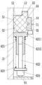
FIG. 1 is a schematic structural diagram of the present invention.
Fig. 2 is an enlarged view of fig. 1 at S.
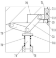
Fig. 3 is an enlarged view at T in fig. 1.
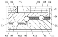
Fig. 4 is an enlarged view of fig. 1 at U.
Fig. 5 is an enlarged view of fig. 1 at W.
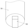
Fig. 6 is a schematic perspective view of the upper stem of the present invention.
List of reference numerals: the valve cap 1, the groove 11, the seal groove 12, the extension groove 13, the side groove 14, the guide hole 15, the escape groove 16, the gland 2, the valve rod 3, the upper valve rod 31, the main rod body 311, the annular limit groove 3111, the L-shaped limit groove 3112, the drive block 312, the threaded rod 32, the drive groove 321, the limit block 4, the lower seal ring 5, the first lip 51, the second lip 52, the third lip 53, the first recess 54, the second recess 55, the self-sealing mechanism 6, the thrust aid 61, the first stepped portion 611, the first annular raceway 6111, the sixth annular raceway 6112, the second stepped portion 612, the second annular raceway 6121, the elastic push rod 62, the upper rod sleeve 621, the pressure plate portion 6211, the inner hole 6212, the lower push rod 622, the first compression spring 623, the universal ball 624, the auxiliary sealing mechanism 7, the transverse pressure block 71, the first projecting portion 711, the second projecting portion 712, the guide 713, the first connecting rod 72, the second connecting rod 73, the push rod 74, the hydraulic valve comprises a transverse plate part 741, a sliding barrel 75, a T-shaped table part 751, a second compression spring 76, a rolling seat 77, a T-shaped sliding groove 771, a first flat table surface 772, a second flat table surface 773, a third annular rolling path 774, a fourth annular rolling path 775, a fifth annular rolling path 776, a first rolling ball 781, a second rolling ball 782, a third rolling ball 783, a retainer 79, a support 8 and a valve body 9.
Detailed Description
In order to make the objects, technical solutions and advantages of the present invention more apparent, the present invention will be described in further detail with reference to the following embodiments and accompanying drawings. The exemplary embodiments and descriptions of the present invention are provided to explain the present invention, but not to limit the present invention.
Referring to fig. 1 to 6, as shown in fig. 1, 5 and 6, an anti-leakage self-sealing valve includes a valve body 9, a valve cover 1, a gland 2, a valve rod 3, a stopper 4, a lower sealing ring 5, a valve plate, a hand wheel, a bracket 8 and a self-sealing mechanism 6, the valve cover 1 is disposed above the valve body 9, the gland 2 is fixed above the valve cover 1 by bolts, the sealing ring is disposed between the gland 2 and the valve cover 1, the bracket 8 is press-fitted between the valve cover 1 and the valve body 9, the stopper 4 is limited in a groove 11 on the valve cover 1 by the gland 2, the valve rod 3 includes an upper valve rod 31 and a threaded rod 32 disposed below the upper valve rod 31, the upper end of the upper valve rod 31 sequentially passes through the valve cover 1 and the gland 2 to be connected with the hand wheel, the upper valve rod 31 can move up and down relative to the valve cover 1, three upper sealing rings are disposed between a main rod body 311 of the upper valve rod 31, the bottom of the annular limiting groove 3111 is provided with an L-shaped limiting groove 3112 for the limiting block 4 to be clamped in, the lower end of the main rod body 311 is connected with a driving block 312, the threaded rod 32 is rotatably arranged on the bracket 8, the threaded rod 32 is in threaded connection with the valve plate, the top end of the threaded rod 32 is provided with a driving groove 321 matched with the driving block 312, when the limiting block 4 is positioned in the annular limiting groove 3111, the driving block 312 is inserted in the driving groove 321, when the limiting block 4 is clamped in the horizontal extension part of the L-shaped limiting groove 3112, the driving block 312 is separated from the driving groove 321, the lower sealing ring 5 is arranged in the sealing groove 12 at the lower part of the valve cover 1, the inner circumference of the lower sealing ring 5 is abutted against the main rod body 311, the self-sealing mechanism 6 comprises a boosting platform 61 and a plurality of elastic push rods 62, the boosting platform 61 is fixedly connected on the main rod body 311, the plurality of elastic push rods 62, the upper end of the elastic push rod 62 abuts against the lower seal ring 5, when the operator pulls the upper valve rod 31 upwards, the upper valve rod 31 drives the boosting platform 61 to abut against the elastic push rod 62, so that the pressing plate portion 6211 at the upper end of the elastic push rod 62 tightly abuts against the lower seal ring 5, and further the lower seal ring 5 deforms and tightly abuts against the main rod body 311 to form sealing.
As shown in fig. 2, the inner circumference of the lower seal ring 5 is provided with a first lip 51 and a second lip 52 at intervals from top to bottom, the first lip 51 and the second lip 52 are both pressed against the outer circumference of the main rod body 311, the outer circumference of the upper portion of the lower seal ring 5 is provided with a third lip 53, and the third lip 53 is press-fitted in the extension groove 13 at the top of the seal groove 12.
In this embodiment, the elastic push rod 62 includes an upper rod sleeve 621, a lower push rod 622 with an upper end movably disposed in the inner hole 6212 of the upper rod sleeve 621, and a first compression spring 623 disposed between the upper rod sleeve 621 and the lower push rod 622, wherein a pressing plate portion 6211 is disposed at the top of the upper rod sleeve 621, and the pressing plate portion 6211 extends into the sealing groove 12.
In this embodiment, the plurality of pressing plate portions 6211 can be combined into a closed annular plate, so that the pressing plate portion 6211 can be pressed against the lower seal ring 5 with good effect.
In this embodiment, the bottom of the lower push rod 622 is provided with a universal ball 624, and the universal ball 624 can roll on the boosting table 61, so that the friction between the bottom end of the elastic push rod 62 and the boosting table 61 when the valve rod 3 rotates is reduced.
As shown in fig. 1, in order to further improve the sealing effect of the lower sealing ring 5, the valve further comprises a plurality of auxiliary sealing mechanisms 7, the plurality of auxiliary sealing mechanisms 7 are distributed around the valve rod 3 at intervals, and the auxiliary sealing mechanisms 7 are used for transversely pressing the lower sealing ring 5 so as to improve the sealing performance of the lower sealing ring 5.
As shown in fig. 3, the auxiliary sealing mechanism 7 includes a transverse pressing block 71, a first connecting rod 72, a second connecting rod 73, a push rod 74, a sliding cylinder 75, a second compression spring 76 and a rolling seat 77, the transverse pressing block 71 is slidably disposed in the side groove 14 outside the sealing groove 12, the inner side of the transverse pressing block 71 is pressed against the outer periphery of the lower sealing ring 5, a guide rod portion 713 outside the transverse pressing block 71 passes through the guide hole 15 on the outer side of the side groove 14 and extends into the escape groove 16 at the other end of the guide hole 15, one end of the first connecting rod 72 extends into the escape groove 16 and is pivotally connected to the guide rod portion 713, the other end of the first connecting rod 72 is pivotally connected to one end of the second connecting rod 73, the other end of the second connecting rod 73 is pivotally connected to the valve cap 1, the upper end of the push rod 74 is pivotally connected to the pivot shafts of the first connecting rod 72 and the second connecting rod 73, the lower end of the push rod 74 is slidably, the upper end of the second compression spring 76 abuts against the transverse plate portion 741 on the upper portion of the push rod 74, the lower end of the second compression spring 76 abuts against the upper end face of the sliding cylinder 75, the lower end of the sliding cylinder 75 is slidably disposed on the rolling seat 77, and the rolling seat 77 is rotatably disposed on the boosting platform 61, so that when the upper valve rod 31 drives the boosting platform 61 to move upwards, the boosting platform 61 drives the sliding cylinder 75 to move upwards through the rolling seat 77, the sliding cylinder 75 pushes the push rod 74 to move upwards through the second compression spring 76, the push rod 74 drives the second connecting rod 73 to swing, the second connecting rod 73 pushes the transverse pressing block 71 through the first connecting rod 72, the transverse pressing block 71 tightly abuts against the outer periphery of the lower seal ring 5, the inner periphery of the lower seal ring 5 tightly abuts against the valve rod 3, and the sealing performance of the lower seal ring 5 is improved.
In this embodiment, a first protrusion 711 and a second protrusion 712 are provided at an interval between the upper right and the lower inside of the lateral pressing piece 71, the first protrusion 711 presses against the first recess 54 on the outer periphery of the lower seal ring 5, and the second protrusion 712 presses against the second recess 55 on the outer periphery of the lower seal ring 5.
As shown in fig. 4, a first step portion 611 is connected to the outer periphery of the boosting stage 61, a second step portion 612 is connected to the outer periphery of the first step portion 611, a plurality of first balls 781, a plurality of second balls 782 and a plurality of third balls 783 are arranged between the bottom of the roller seat 77 and the first and second step portions 611 and 612 through the second step portion 612, the bottom of the first balls 781 is arranged to roll in a first annular raceway 6111 at the top of the first step portion 611, the top of the first balls 781 is arranged to roll in a third annular raceway 774 on a first flat land 772 at the bottom of the roller seat 77, one side of the second balls 782 is arranged to roll in a fourth annular raceway 775 at the bottom of the roller seat 77, the other side of the second balls 782 is arranged to roll in a sixth annular raceway 6112 on the outer edge of the first step portion 611, the bottom of the third balls 783 is arranged to roll in a second annular raceway 6121 at the top of the second step portion 612, the top of the third ball 783 is arranged in the fifth annular rolling path 776 on the second flat platform surface 773 at the bottom of the roller seat 77 in a rolling manner, and the arrangement of the structure enables the roller seat 77 to flexibly and stably rotate relative to the boosting platform 61.
In this embodiment, a T-shaped chute 771 is provided at the top of the roller seat 77, and a T-shaped table portion 751 which is engaged with the T-shaped chute 771 is provided at the lower portion of the slide cylinder 75.
As shown in fig. 1, in daily use, the driving block 312 at the bottom of the upper valve rod 31 is inserted into the driving groove 321 at the top of the threaded rod 32, so that when the hand wheel is rotated, the upper valve rod 31 can drive the threaded rod 32 to rotate synchronously through the driving block 312 and the driving groove 321 which are matched, and the first compression spring 623 and the second compression spring 76 are both in a natural state, so that the lower sealing ring 5 is also in a natural state, thereby preventing the lower sealing ring 5 from being in a compressed state for a long time and prolonging the service life of the lower sealing ring 5; when the upper sealing ring needs to be replaced, a user firstly pulls the upper valve rod 31 upwards with force to separate the driving block 312 from the driving groove 321 until the limiting block 4 moves to the bottom of the vertical extending part of the annular limiting groove 3111, so that the upper valve rod 31 cannot move upwards continuously, then the upper valve rod 31 is rotated to enable the limiting block 4 to be clamped into the horizontal extending part of the annular limiting groove 3111, at the moment, the first compression spring 623 and the second compression spring 76 are both in a compression state, and further the lower sealing ring 5 is deformed to tightly abut against the upper valve rod 31 to form sealing, and the purpose that the upper sealing ring is replaced by pressing the water hose continuously can be achieved.
The above description is only a preferred embodiment of the present invention, and is not intended to limit the present invention, and various modifications and changes may be made to the embodiment of the present invention by those skilled in the art. Any modification, equivalent replacement, or improvement made within the spirit and principle of the present invention should be included in the protection scope of the present invention.
Claims (10)
1. The utility model provides a prevent outer hourglass self sealss valve, includes valve body (9), valve gap (1), gland (2), valve rod (3), stopper (4), lower seal circle (5), valve plate and hand wheel, its characterized in that still includes self sealss mechanism (6) and support (8), support (8) are pressed fitting in valve gap (1) with between valve body (9), valve rod (3) are in including last valve rod (31) and setting threaded rod (32) of going up valve rod (31) below, it can be relative to go up valve rod (31) valve gap (1) is movable from top to bottom, threaded rod (32) rotate to set up on support (8), just threaded rod (32) with valve plate threaded connection, go up be provided with on mobile jib body (311) of valve rod (31) with stopper (4) matched with annular spacing groove (3111), the bottom of annular spacing groove (3111) be provided with stopper (4) matched with L shape spacing Groove (3112), the lower extreme of the body of the mast (311) is connected and is provided with drive block (312), the top of threaded rod (32) be provided with drive groove (321) of drive block (312) looks adaptation, work as stopper (4) card go into when the horizontal extension of L shape spacing groove (3112) is interior, drive block (312) with drive groove (321) separation, install down sealing washer (5) in seal groove (12) of valve gap (1) lower part, the interior week of lower sealing washer (5) supports and presses on the body of the mast (311), self-sealing mechanism (6) are including helping push platform (61) and a plurality of elastic push rod (62), help push platform (61) rigid coupling is in on the body of the mast (311), a plurality of elastic push rod (62) encircle the body of the mast (311) interval sets up, the lower extreme of elastic push rod (62) supports and presses on helping push platform (61), the upper end of the elastic push rod (62) is pressed against the lower sealing ring (5).
2. The leak-proof self-sealing valve according to claim 1, wherein the lower sealing ring (5) is provided with a first lip (51) and a second lip (52) at intervals on the inner circumference, the first lip (51) and the second lip (52) are both pressed against the outer circumference of the main rod body (311), a third lip (53) is provided on the outer circumference of the upper portion of the lower sealing ring (5), and the third lip (53) is press-fitted in the extension groove (13) at the top of the sealing groove (12).
3. The leak-proof self-sealing valve according to claim 2, wherein the top of the elastic push rod (62) is provided with a pressing plate portion (6211), and the pressing plate portion (6211) is pressed against the lower sealing ring (5).
4. The leak-proof self-sealing valve as claimed in claim 3, wherein the bottom of the elastic push rod (62) is provided with a universal ball (624), and the universal ball (624) can roll on the boosting platform (61).
5. The anti-leakage self-sealing valve according to claim 4, wherein the elastic push rod (62) comprises an upper rod sleeve (621), a lower push rod (622) with the upper end movably arranged in an inner hole (6212) of the upper rod sleeve (621), and a first compression spring (623) arranged between the upper rod sleeve (621) and the lower push rod (622), the pressing plate part (6211) is connected and arranged at the top end of the upper rod sleeve (621), and the universal ball (624) is arranged at the bottom end of the lower push rod (622).
6. The leak-proof self-sealing valve according to claim 2 or 5, further comprising a plurality of auxiliary sealing mechanisms (7), wherein the plurality of auxiliary sealing mechanisms (7) are distributed around the valve rod (3) at intervals, the auxiliary sealing mechanisms (7) comprise a transverse pressing block (71), a first connecting rod (72), a second connecting rod (73), a top rod (74), a sliding cylinder (75), a second compression spring (76) and a rolling seat (77), the transverse pressing block (71) is slidably arranged at the bottom of the valve cap (1), the transverse pressing block (71) is pressed against the periphery of the lower sealing ring (5), one end of the first connecting rod (72) is pivoted on the transverse pressing block (71), the other end of the first connecting rod (72) is pivoted with one end of the second connecting rod (73), the other end of the second connecting rod (73) is pivoted on the valve cap (1), the upper end of the ejector rod (74) is pivoted on a pivoting shaft of the first connecting rod (72) and the second connecting rod (73), the lower end of the ejector rod (74) is arranged in the sliding cylinder (75) in a sliding mode, the second compression spring (76) is arranged between the ejector rod (74) and the sliding cylinder (75), the lower end of the sliding cylinder (75) is arranged on the rolling seat (77) in a sliding mode, and the rolling seat (77) is arranged on the boosting platform (61) in a rotating mode.
7. The leak-proof self-sealing valve according to claim 6, wherein the transverse pressing block (71) is provided with a first protrusion (711) and a second protrusion (712) at intervals, the first protrusion (711) is pressed in the first recess (54) on the outer periphery of the lower sealing ring (5), and the second protrusion (712) is pressed in the second recess (55) on the outer periphery of the lower sealing ring (5).
8. The anti-leakage self-sealing valve according to claim 7, wherein a first step portion (611) is connected to the outer periphery of the booster stage (61), a second step portion (612) is connected to the outer periphery of the first step portion (611), a plurality of first balls (781) are arranged between the bottom of the roller seat (77) and the first step portion (611), the bottom of the first balls (781) is arranged in a first annular rolling way (6111) on the top of the first step portion (611) in a rolling way, the top of the first balls (781) is arranged in a third annular rolling way (774) on a first flat platform surface (772) on the bottom of the roller seat (77) in a rolling way, a plurality of third balls (783) are arranged between the bottom of the roller seat (77) and the second step portion (612), and the bottom of the third balls (783) is arranged in a second annular rolling way (6121) on the top of the second step portion (612) in a rolling way, the top of the third ball (783) is arranged in a fifth annular raceway (776) on a second flat table surface (773) at the bottom of the roller seat (77) in a rolling mode.
9. The leak-proof self-sealing valve according to claim 8, wherein a plurality of second balls (782) are further disposed between the roller seat (77) and the first step portion (611), one side of the second balls (782) is disposed in a fourth annular raceway (775) at a bottom corner of the roller seat (77) in a rolling manner, and the other side of the second balls (782) is disposed in a sixth annular raceway (6112) on an outer edge of the first step portion (611) in a rolling manner.
10. The leak-proof self-sealing valve as claimed in claim 6, wherein the top of the rolling seat (77) is provided with a T-shaped chute (771), and the lower part of the sliding cylinder (75) is provided with a T-shaped terrace portion (751) matched with the T-shaped chute (771).
Priority Applications (1)
| Application Number | Priority Date | Filing Date | Title |
|---|---|---|---|
| CN202010889558.5A CN111981194A (en) | 2020-08-28 | 2020-08-28 | Anti-leakage self-sealing valve |
Applications Claiming Priority (1)
| Application Number | Priority Date | Filing Date | Title |
|---|---|---|---|
| CN202010889558.5A CN111981194A (en) | 2020-08-28 | 2020-08-28 | Anti-leakage self-sealing valve |
Publications (1)
| Publication Number | Publication Date |
|---|---|
| CN111981194A true CN111981194A (en) | 2020-11-24 |
Family
ID=73441213
Family Applications (1)
| Application Number | Title | Priority Date | Filing Date |
|---|---|---|---|
| CN202010889558.5A Withdrawn CN111981194A (en) | 2020-08-28 | 2020-08-28 | Anti-leakage self-sealing valve |
Country Status (1)
| Country | Link |
|---|---|
| CN (1) | CN111981194A (en) |
Cited By (1)
| Publication number | Priority date | Publication date | Assignee | Title |
|---|---|---|---|---|
| CN113636216A (en) * | 2021-07-26 | 2021-11-12 | 何春香 | Automatic storage temperature control system applied to cold chain transportation |
Citations (5)
| Publication number | Priority date | Publication date | Assignee | Title |
|---|---|---|---|---|
| CN203628011U (en) * | 2013-12-18 | 2014-06-04 | 泉州市沪航阀门制造有限公司 | Out-leakage-preventing self-sealing valve |
| CN105020465A (en) * | 2014-04-22 | 2015-11-04 | 洪宝玉 | Bothway pressure-bearing soft seal sluice valve |
| CN106287108A (en) * | 2016-11-19 | 2017-01-04 | 西南石油大学 | A kind of combination type speed governing wiper |
| CN209587317U (en) * | 2018-11-29 | 2019-11-05 | 浙江艾柯暖通科技有限公司 | A kind of telescopic ball valve spanner |
| JP2020084781A (en) * | 2018-11-16 | 2020-06-04 | Nok株式会社 | Sealing structure |
-
2020
- 2020-08-28 CN CN202010889558.5A patent/CN111981194A/en not_active Withdrawn
Patent Citations (5)
| Publication number | Priority date | Publication date | Assignee | Title |
|---|---|---|---|---|
| CN203628011U (en) * | 2013-12-18 | 2014-06-04 | 泉州市沪航阀门制造有限公司 | Out-leakage-preventing self-sealing valve |
| CN105020465A (en) * | 2014-04-22 | 2015-11-04 | 洪宝玉 | Bothway pressure-bearing soft seal sluice valve |
| CN106287108A (en) * | 2016-11-19 | 2017-01-04 | 西南石油大学 | A kind of combination type speed governing wiper |
| JP2020084781A (en) * | 2018-11-16 | 2020-06-04 | Nok株式会社 | Sealing structure |
| CN209587317U (en) * | 2018-11-29 | 2019-11-05 | 浙江艾柯暖通科技有限公司 | A kind of telescopic ball valve spanner |
Cited By (1)
| Publication number | Priority date | Publication date | Assignee | Title |
|---|---|---|---|---|
| CN113636216A (en) * | 2021-07-26 | 2021-11-12 | 何春香 | Automatic storage temperature control system applied to cold chain transportation |
Similar Documents
| Publication | Publication Date | Title |
|---|---|---|
| KR970006376B1 (en) | Metal diaphragm valve | |
| CN109899534B (en) | Butterfly valve | |
| CN111981194A (en) | Anti-leakage self-sealing valve | |
| CN104791501A (en) | Bi-directional pressure self-balancing type stop valve | |
| CN207999508U (en) | A kind of convertible double disc operated pneumatic valve | |
| CN110159811B (en) | Pressure regulating overflow valve of high-pressure pump | |
| CN207848519U (en) | Piloted reducer | |
| CN109237056B (en) | Cartridge formula preforming valve | |
| CN210014024U (en) | Novel plate valve | |
| CN109882593B (en) | Pressure-adjustable double-sided compression sealing device | |
| CN201547249U (en) | High-pressure pneumatic stop valve | |
| CN209414709U (en) | A kind of super-pressure automatic draining device | |
| CN209262292U (en) | Novel H-type descaling injection valve | |
| CN210153239U (en) | Butterfly valve rod seal structure | |
| CN201731118U (en) | Plug-in mounting type hydraulic-control one-way valve | |
| CN202132202U (en) | Two-stage compressor and upper flange component thereof | |
| CN211715776U (en) | Single-seat regulating valve core structure with quick-change sealing surface | |
| CN212203179U (en) | Forged steel gate valve | |
| CN2475826Y (en) | Polish rod sealing device for oil pumping well head | |
| CN218207912U (en) | Butterfly eccentric rotary ball valve | |
| CN201103727Y (en) | Balance type check valve | |
| CN202493684U (en) | Diaphragm type pressure reducing valve | |
| CN208364843U (en) | A kind of screw slots floating position-limiting seat two way seal semisphere valve | |
| CN2201539Y (en) | Single spring prepressing valve | |
| CN205918937U (en) | Ball valve that leakproofness is strong |
Legal Events
| Date | Code | Title | Description |
|---|---|---|---|
| PB01 | Publication | ||
| PB01 | Publication | ||
| SE01 | Entry into force of request for substantive examination | ||
| SE01 | Entry into force of request for substantive examination | ||
| WW01 | Invention patent application withdrawn after publication |
Application publication date: 20201124 |
|
| WW01 | Invention patent application withdrawn after publication |