CN1119257C - Supporting structure for body cover of two-wheel motor vehicle - Google Patents
Supporting structure for body cover of two-wheel motor vehicle Download PDFInfo
- Publication number
- CN1119257C CN1119257C CN98105542A CN98105542A CN1119257C CN 1119257 C CN1119257 C CN 1119257C CN 98105542 A CN98105542 A CN 98105542A CN 98105542 A CN98105542 A CN 98105542A CN 1119257 C CN1119257 C CN 1119257C
- Authority
- CN
- China
- Prior art keywords
- vehicle frame
- body cover
- vehicle body
- mentioned
- cover
- Prior art date
- Legal status (The legal status is an assumption and is not a legal conclusion. Google has not performed a legal analysis and makes no representation as to the accuracy of the status listed.)
- Expired - Fee Related
Links
Images


Abstract
To properly support a body cover on a car body frame on a motor bicycle furnished with the car body frame integrally molded of light alloy or a synthetic resin. Guide grooves 274 sandwiched by upper part protruded wires 272 and lower part protruded wires 273 are furnished on both left and right side parts of a main frame 27 corresponding to a floor tunnel part on a car body frame of a scooter type motor bicycle integrally molded of light alloy. Left and right floor panels 14L, 14R constituting a part of a body cover are fixed on a floor bracket 36 in a state where their inner edges are engaged with the guide grooves 274 . A part of the main frame 27 is exposed upward from the floor panels 14L, 14R and constitutes a part of an outer appearance member.
Description
Technical field
The present invention relates to the vehicle body cover supporting structure of motor bike, this motor bike has with light alloy or the integrally formed vehicle frame of synthetic resin.
Background technology
Usually, the vehicle frame of motor bike is dressed up the steel pipe soldering group, for topped this vehicle frame plastic vehicle body cover (referring to for example Japanese special fair 5-39836 communique) is installed.
; in recent years; motor bike with the integrally formed vehicle frame of light alloys such as aluminium has appearred having; if but when covering the much higher light alloy system vehicle frame of hidden Design freedom of living the vehicle frame shape of making than the steel pipe welding fully, just can not bring into play the rare characteristic of light alloy system vehicle frame fully with the vehicle body cover.Therefore, consider the part of light alloy system vehicle frame is exposed from the vehicle body cover, it is utilized as a part of appearance part.But in this case,, then between two parts, produce the gap, not only influence attractive in appearancely, and may cause the supporting instability of vehicle body cover ora terminalis if the connecting portion of vehicle frame and vehicle body cover is not suitably handled.
Summary of the invention
The present invention makes in view of the above problems, its objective is in the motor bike that has the vehicle frame integrally formed by light alloy or synthetic resin, supports the vehicle body cover on its vehicle frame rightly.
In the present invention, in the time of on the vehicle body cover being bearing in the vehicle frame integrally formed by light alloy or synthetic resin, because the ora terminalis of vehicle body cover is engaged with the guide groove that is formed on frame side, so, the vehicle body cover correctly can be located also and be bearing on the vehicle frame really.In addition,, also can be embedded in this scale error that partially absorbs of guide groove, prevent the generation in gap, increase attractive in appearance with the ora terminalis of vehicle body cover even vehicle body cover and vehicle frame have some scale errors.In addition,,, more increased attractive in appearancely, and can reduce number of parts so the design-calculated degree of freedom increases because the part of vehicle frame that will be exposed to the top from the vehicle body cover is as appearance part.
In addition, the present invention can support the body weight of bearing the jockey certain and attractive in appearancely, the showy base plate from the outside.
In addition, the present invention can support certain and attractive in appearancely and bear the load that produced by the wind that travels, the showy legging cover from the outside.
In addition, when the ora terminalis with the vehicle body cover engages with the guide groove of vehicle frame, below the vehicle body cover, be bearing on the copulational protuberance of guide groove below in the present invention, so, can support the load that is added on the vehicle body cover more effectively.
In addition, the present invention is owing to the vehicle body cover is supported by several copulational protuberances, so make this supporting more practical.
In addition, the present invention is because when being shaped with forming die, the longitudinal plane of symmetry injection liquation from vehicle frame so liquation flows to the left and right sides of vehicle frame equably, can improve the quality.And when rib that the vehicle frame longitudinal plane of symmetry of fine limit work after being shaped extends, gate portions is cut automatically, so the vestige of this gate part is not obvious, can increase attractive in appearance.
Description of drawings
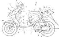
Fig. 1 is motor-scooter type moped whole lateral plan.
Fig. 2 is 2 direction of arrow views of Fig. 1.
Fig. 3 is the block diagram of vehicle frame.
Fig. 4 is the arrow 4 direction views of Fig. 3.
Fig. 5 be Fig. 1 want portion's enlarged drawing.
Fig. 6 is the arrow 6 direction views of Fig. 5.
Fig. 7 is the 7-7 line section-drawing of Fig. 6.
Fig. 8 is the 8-8 line section-drawing of Fig. 6.
Fig. 9 is the 9-9 line section-drawing of Fig. 6.
Figure 10 is the 10-10 line section-drawing of Fig. 3.
Figure 11 is the instruction diagram with the cooresponding variation of Figure 10.
Figure 12 is the cross sectional drawing of the shaping die of casting vehicle frame.
The specific embodiment
Below, the embodiments of the invention shown in illustrate embodiments of the invention with reference to the accompanying drawings.
Fig. 1 to Figure 12 represents one embodiment of the invention.Fig. 1 is motor-scooter type moped whole lateral plan.Fig. 2 is the arrow 2 direction views of Fig. 1.Fig. 3 is the block diagram of vehicle frame.Fig. 4 is the arrow 4 direction views of Fig. 3.Fig. 5 be Fig. 1 want portion's enlarged drawing.Fig. 6 is the arrow 6 direction views of Fig. 5.Fig. 7 is the 7-7 line section-drawing of Fig. 6.Fig. 8 is the 8-8 line section-drawing of Fig. 6.Fig. 9 is the 9-9 line section-drawing of Fig. 6.Figure 10 is the 10-10 line section-drawing of Fig. 3.Figure 11 is the instruction diagram with the cooresponding variation of Figure 10.Figure 12 is the cross sectional drawing of the shaping die of casting vehicle frame.
As depicted in figs. 1 and 2, motor-scooter type moped V has by the integrally formed vehicle frame F of aluminum alloy.Head pipe 1 is located at the front portion of vehicle frame F integratedly, but front fork 2 left rotation and right rotation be bearing on this pipe 1.Front-wheel W is supported with axle in lower end at front fork 2
f, the upper end be provided with by handlebar cover 3 topped rod 4.The trailing wheel W that has driving engine 5, transmission device 6 and drive by them
rPower unit P can be bearing in the rear lower of vehicle frame F by power unit suspending rod 7 with swinging up and down.The rear end of power unit P is connected by posterior bumper 8 with the rear end of vehicle frame F.See that from the plane two ends of the control subframe 9 that slightly is the U font are fixed on the rear end of vehicle frame F, these subframe 9 upper supports Fuel Tank 20.
The vehicle body cover B of motor bike V, by upper plate 11 before the legging cover of the upper front of topped head pipe 1, with this legging cover before plate 13 behind the legging cover of lower plate 12, topped two legging cover header boards 11,12 back before the bottom bonded assembly legging cover of upper plate 11, with the bonded assembly left and right sides, the bottom base plate 14 of vehicle frame F
L, 14
R, topped two base plates 14
L, 14
R End cover 15, the left and right sides back cover 16 at topped vehicle frame F rear portion
L, 16
RConstitute.From Fig. 1 as seen, by plate 13, left and right sides base plate 14 behind the legging cover
L, 14
RAnd left and right sides back cover 16
L, 16
RThe part of surrounding, i.e. part between the pin of the jockey left and right sides (Off ロ ア ト Application Woo Le part), vehicle frame F is exposed, and constitutes the part of appearance part in the vehicle frame F of this exposed portions serve.
At left and right sides back cover 16
L, 16
RInside, accommodating be used to place the helmet 17 grades accommodate case 18, fuel tank 19 and Fuel Tank 20, their top is topped by opening and closing freely vehicle seat 21.
Can find out as Fig. 3 and Fig. 4,, have the battery case 26 that the supporting battery is used in the front portion of head pipe 1 by the integrally formed vehicle frame F of aluminium alloy casting.At the rear portion of head pipe 1, the section of the open underneath of ining succession slightly is the main car frame 27 of U font (see figure 7), and then the slightly smooth back vehicle frame 28 of ining succession at the rear portion of this main car frame 27.From the beginning manage 1 lower end until the anterior lower edge of main car frame 27, each 4 lug boss 27 about formation
1, at this lug boss 27
1On, with bolt 30 ... fix the vehicle frame rigidity that constitutes by pair of right and left iron plate and regulating parts 29,29.
As can be seen from Figure 10, anchor clamps 29
1Be formed on each vehicle frame rigidity and regulate on the parts 29, rope, the flexible pipe base part 33 of air door rope, electric wiring, brake hose etc. are sandwiched in these anchor clamps.Like this, special anchor clamps needn't be set, can reduce number of parts.In addition, also variation is such as shown in figure 11, with about the vehicle frame rigidity regulate parts 29,29 and be linked to be コ font section and being made of one.
In conjunction with just finding out, near the lower edge of the left and right sides of main car frame 27, with the prominent abreast top raised line 27 that extends along its total length of establishing of predetermined space with reference to Fig. 7 and Fig. 8
2, 27
2With bottom raised line 27
3, 27
3, at two raised lines 27
2, 27
2, 27
3, 27
3Between form guide groove 27
4, 27
4Also have, in the bottom, the left and right sides of main car frame 27, the prominent pair of right and left lug boss 27 of establishing
5, 27
5(see figure 7) and copulational protuberance 27
6, 27
6(see figure 8), this lug boss 27
5, 27
5Support the front portion of bottom bracket 36 described later, this copulational protuberance 27
6, 27
6Supporting is based in aforementioned left and right sides base plate 14
L, 14
RFollowing joint 14
1, 14
1In addition, on main car frame 27, prominent establishing support the following pair of right and left copulational protuberance 27 of plate behind the above-mentioned legging cover 13
7, 27
7(seeing Fig. 3 and Fig. 5).
From Fig. 3 and Fig. 9 as can be seen, right pipe-hanging hook 28 is prominently integratedly being established in the position of keeping right below the vehicle frame 28 of back
1Right pipe-hanging hook 28
1Inside be hollow, form drain gutter 28 at basifacial thereafter
6Also have, the position that keeps left below the vehicle frame 28 of back is being fixed and above-mentioned right pipe-hanging hook 28 by 2 bolts 32,32
1Synergistic iron plate system left side pipe-hanging hook 31.And then, form 2 bolts hole 28 that are used for fixing above-mentioned subframe 9 respectively in the left and right side of back vehicle frame 28
4
What as shown in Figure 4, be provided with open upper part on the vehicle frame 28 in the back accommodates recess 28
13, this accommodates recess 28
13Has the front side wall 28 that erects upward
9, rear wall 28
10With left and right sides sidewall 28
11, 28
12Accommodating case 18 is installed on the vehicle frame 28 of back, its at least a portion is housed in the above-mentioned recess 28 of accommodating
13In.
On the vehicle frame 28 of back, form 2 bolts hole 28
2, 28
2With several bolts hole 28
3Above-mentioned 2 bolts 32,32 of fixing left pipe-hanging hook 31 run through this 2 bolts hole 28
2, 28
2, fixing above-mentioned bolt (figure does not show) of accommodating case 18 runs through this several bolts hole 28
3Also have, be formed for the maintenance opening 28 of the loading and unloading of freeing pipe 10 (see figure 2)s or the loading and unloading of light-up plug etc. at the central portion of back vehicle frame 28
7, fuel tank 19 in its rear mounting simultaneously, and then also form from the flexible pipe through port 28 of this fuel tank 19 to driving engine 5 fuel feeding
8At above-mentioned flexible pipe through port 28
8The left side form posterior bumper installation portion 28
14
Figure 12 is the skiagraph that is expressed as pattern D, and this forming die D is used for the die casting shaping and has the vehicle frame F of above-mentioned structure.Forming die D is by fixed die D
1But, dynamic model D
2With sliding die D
3Constitute fixed die D
1But with dynamic model D
2Division plane be positioned on the longitudinal plane of symmetry of cavity C of vehicle frame F.And by from being formed on fixed die D
1But with dynamic model D
2Division plane on several (for example 4) cast gate G inject liquation, liquation flows in the cavity C of left-right symmetric shape equably, uniform high quality vehicle frame F about can obtaining.In the upper central of the main car frame 27 of vehicle frame F, form the rib 27 that extends along fore-and-aft direction
8(seeing Fig. 3 and Fig. 4) is after the vehicle frame F casting, to rib 27
8Ora terminalis when carrying out fine limit work, coupled gate part is cut automatically.Like this, the connecting portion of above-mentioned gate part is unshowy, can increase the attractive in appearance of vehicle frame F.
, on main car frame 27, be provided with and be used to support left and right sides base plate 14 to shown in Figure 9 as Fig. 5
L, 14
RThe bottom bracket 36 of while hog frame main car frame 27.Bottom bracket 36 is by the pair of right and left curb girder 37 that extends along the vehicle body fore-and-aft direction
L, 37
R, connect two curb girders 37
L, 37
RCrossbeam 38 between front end, be located at the anterior fixed parts 39 of pair of right and left on the crossbeam 38
L, 39
R, be located at two curb girders 37
L, 37
RThe pair of right and left rear portion fixed parts 40 at rear portion
L, 40
RConstitute.Fixing loudspeaker 41 in the central authorities of crossbeam 38.And, pass through by bolt 42,42 (see figure 7)s its anterior fixed parts 39 in the front portion of bottom bracket 36
L, 39
RBe fastened on the lug boss 27 of main car frame 27
5, 27
5Go up and be bearing on the vehicle frame F, also have, the rear portion of bottom bracket 36 is passed through by pivot bolt 43 (see figure 9)s its rear portion fixed parts 40
L, 40
RBe fastened on above-mentioned left and right sides pipe-hanging hook 31,28
1Go up and be bearing on the vehicle frame F.
Can find out left and right sides base plate 14 by Fig. 6 to Fig. 8
L, 14
R, edge is embedded in the guide groove 27 of main car frame 27 within it
4, 27
4Under the interior state, be fastened on the curb girder 37 of bottom bracket 36 by pair of right and left bolt 44,44
L, 37
RThe front portion, and then be fastened on above-mentioned curb girder 37 by pair of right and left bolt 45,45
L, 37
RThe rear portion.At this moment, be darted at base plate 14
L, 14
RFollowing joint 14
1, 14
1Below, be bearing in the copulational protuberance 27 of main car frame 27
6, 27
6Top (see figure 8).
Like this, base plate 14
L, 14
RBecause its inner rim is bearing in the top raised line 27 that is formed at main car frame 27
2, 27
2With bottom raised line 27
3, 27
3Between guide groove 27
4, 27
4In, and joint 14
1, 14
1Be bearing in the copulational protuberance 27 of main car frame 27
6, 27
6On, so, act on base plate 14
L, 14
RThe load of rider's weight etc. can pass to main car frame 27 effectively, the load that bottom bracket 36 bears can be distributed on the main car frame 27.And, even main car frame 27 and base plate 14
L, 14
RBetween some scale errors are arranged, then since this scale error also can be by base plate 14
L, 14
RInner edge and guide groove 27
4, 27
4Telescoping part absorb, so can prevent to increase attractive in appearance in this part generation gap.
Equally, behind the legging cover inner edge of plate 13 also with the guide groove 27 of main car frame 27
4, 27
4Engage, so with its inner rim following with the copulational protuberance 27 of main car frame 27
7, 27
7The state that (see figure 3) is joined is fixed.Like this, plate 13 behind the legging cover positively is bearing on the main car frame 27, can sustains the blast of driving wind, and, the connecting portion of two parts is not produced with gap supporting attractive in appearancely.
From Fig. 5, Fig. 6 and Fig. 9 can find out, power unit suspending rod 7 can swing up and down the front end of power unit P and be bearing in freely on the vehicle frame F, and this suspending rod 7 is by outer tube 46, be sintered to fix the circular elastomeric element 47 in week in outer tube 46 two ends, 47, be sintered to fix in two elastic portion spare 47, pipe 48 in the pair of right and left in week in 47,48, be disposed at pipe 48 in two, distance ring 49 between 48, from a pair of strut 50 of outer tube 46 to back lower place extension, 50, connect two struts 50, the back pipe 51 of 50 rear ends, constitute to front upper place blocking arm 52 that extends and the elastomeric element 53 that is located at blocking arm 52 front ends from outer tube 46.
Above-mentioned pivot bolt 43 connects the rear portion fixed parts 40 in the left side of bottom bracket 36
L, be fixed on manage 48 in the iron plate system left side pipe-hanging hook 31 of back on the vehicle frame 28, the left side in pipe 48, distance ring 49, the right side, packing ring 54, be formed on after right pipe-hanging hook 28 on the vehicle frame 28
1And the rear portion fixed parts 40 on the right side of bottom bracket 36
RAnd screw togather with nut 55.Also have, the bolted connection that back pipe 51 does not show by figure is in power unit P front end.Like this, the state below power unit suspending rod 7 is supported on back vehicle frame 28, blocking arm 52 is housed in the recess 28 that is formed at back vehicle frame 28 with the elastomeric element 53 that is located at its front end
5In (referring to Fig. 5), by elastomeric element 53 and recess 28
5Upper wall surface join and the rotation end of restricted power unit suspending rod 7.
When power unit P above-below direction is swung, connect outer tube 46 with elastomeric element 47,47 torsional deflectioies of interior pipe 48,48 as power unit P when moving up and down or front and back are moving, above-mentioned elastomeric element 47,47 is at radial direction generation compressive deformation and buffering vibration.When fastening pivot bolt 43, because iron plate system left side pipe-hanging hook 31 is at the left and right directions elastic deformation, so, can make the axle power of pivot bolt 43 stable, and can avoid big load action aluminum alloy system right side pipe-hanging hook 28 to high stiffness
1On.
But, if pass through the load of power unit suspending rod 7 inputs only by left and right sides pipe-hanging hook 31,28 from power unit P
1During supporting, just have and to improve these pipe-hanging hooks 31,28
1Intensity and produce the problem that weight increases.But, in the present embodiment, because left and right sides pipe-hanging hook 31,28
1Be connected by the middle body of bottom bracket 36 with main car frame 27, so, can make to input to pipe-hanging hook 31,28
1Load disperse, can make these pipe-hanging hooks 31,28
1Miniaturization and expendable weight.
In addition, though the left and right sides curb girder 37 of bottom bracket 36
L, 37
RConnecting by crossbeam 37, but be provided in a side of rear portion, the left and right sides fixed parts 40 of rear end side at front end
L, 40
RDo not interconnect, so two rear portion fixed partss 40
L, 40
RConnect indirectly by pivot bolt 43.Usually, as everyone knows, though moderately lower the road-holding property that the vehicle frame rigidity can improve motor bike, if the left and right sides curb girder 37 of bottom bracket 36
L, 37
RThe rear end connect with special crossbeam, then having owing to pivot bolt 43 causes rigidity increases the related excessive possibility of vehicle frame rigidity that makes.
But, in the present embodiment, owing to saved connection left and right sides curb girder 37
L, 37
RThe crossbeam of rear end is born this function by pivot bolt 43, so, vehicle frame rigidity appropriateness is reduced, not only can improve road-holding property, and can be owing to reducing number of parts expendable weight, cost-cutting.
More than, describe embodiments of the invention in detail, but can in the scope that does not break away from spirit of the present invention, make various design modifications.
For example, in an embodiment, vehicle frame F constitutes with aluminum alloy, but also can constitute with other light alloy or synthetic resin.In addition, be bearing in guide groove 27
4, 27
4In the vehicle body cover be not limited to plate 13 and base plate 14 behind the legging cover
L, 14
R, also can be other vehicle body cover arbitrarily.
According to first technical scheme of the present invention, owing to form guide groove at sidepiece by the integrally formed vehicle frame of light alloy or synthetic resin, make the ora terminalis of vehicle body cover chimeric and be bearing in this guide groove, the part of vehicle frame is exposed to the top from the vehicle body cover, so, the vehicle body cover correctly can be located and is bearing on the vehicle frame, and, even vehicle body cover and vehicle frame have some scale errors, also can prevent between two parts, to produce the gap, increase attractive in appearance.In addition, as appearance part,, more increased attractive in appearancely, and can reduce number of parts so not only the design-calculated degree of freedom increases because the part of vehicle frame is exposed to the top.
According to a second technical aspect of the present invention, because the vehicle body cover is base plate, so, can support the body weight of bearing the jockey, showy base plate from the outside certain and attractive in appearancely.
According to a third technical aspect of the present invention, because the vehicle body cover is the legging cover, so, can support certain and attractive in appearancely and bear the load that produces by the wind that travels, showy legging cover from the outside.
According to a fourth technical aspect of the present invention, because vehicle frame has copulational protuberance below guide groove, below this copulational protuberance supporting vehicle body cover,, can support the vehicle body cover more effectively so the load that acts on the vehicle body cover is born by copulational protuberance.
According to the 5th technical scheme of the present invention, because copulational protuberance is formed on some places of vehicle frame, so, can support the vehicle body cover more effectively.
According to the 6th technical scheme of the present invention, owing to vehicle frame has the rib that extends along its longitudinal plane of symmetry, when being shaped this vehicle frame, from end edge portion branch injection the melting liquid of this rib, so the liquid that melts when the shaping vehicle frame flows well, can improve the quality with forming die.And when shaping the above-mentioned rib of back goods, gate part is automatically cut, so the vestige of gate part is not obvious, can increase attractive in appearance.
Claims (6)
1. the vehicle body cover of motor bike is characterized in that, be shaped the integratedly vehicle frame (F) of section U font of light alloy or rigid resin, forms guide groove (27 at the left and right sides of above-mentioned vehicle frame (F) sidepiece at the rear of a pipe
4), in the bottom of above-mentioned vehicle frame (F) bottom bracket (36) is set, make the medial extremity and the above-mentioned guide groove (27 of the base plate (14L, 14R) that constitutes the vehicle body cover
4) combination, and the outside of above-mentioned base plate (14L, 14R) is fixed on the above-mentioned bottom bracket (36).
2. the vehicle body cover of motor bike as claimed in claim 1, it is characterized in that above-mentioned bottom bracket (36) is made of with the side member that is connected them (37L, 37R) with the back supporting member that is installed in the vehicle frame rear lower (40L, 40R) the preceding supporting member (38) that is installed in the preceding bottom of vehicle frame (F).
3. the vehicle body cover of motor bike as claimed in claim 1, it is characterized in that, the medial extremity of the legging cover that will be provided with continuously with the base plate front upper part combines with above-mentioned guide groove, the external side end of this legging cover is supported on before the legging cover of formation vehicle body cover of the front side that is located at the legging cover before the upper plate (11) and legging cover on the lower plate (12).
4. the vehicle body cover of motor bike as claimed in claim 1 is characterized in that, above-mentioned vehicle frame (F) is at guide groove (27
4) the below have copulational protuberance (27
6, 27
7), by this copulational protuberance (27
6, 27
7) support below the base plate (14R, 14L) that constitutes above-mentioned vehicle body cover.
5. the vehicle body cover of motor bike as claimed in claim 4 is characterized in that, above-mentioned copulational protuberance (27
6, 27
7) be formed on the many places of above-mentioned vehicle frame (F).
6. the vehicle body cover of motor bike as claimed in claim 1 is characterized in that, the rib that the injection liquation that uses when also having the shaping vehicle frame is used is along the structure of the longitudinal plane of symmetry extension of vehicle frame.
Applications Claiming Priority (3)
| Application Number | Priority Date | Filing Date | Title |
|---|---|---|---|
| JP08248097A JP3838592B2 (en) | 1997-04-01 | 1997-04-01 | Motorcycle body cover support structure |
| JP082480/97 | 1997-04-01 | ||
| JP082480/1997 | 1997-04-01 |
Publications (2)
| Publication Number | Publication Date |
|---|---|
| CN1194929A CN1194929A (en) | 1998-10-07 |
| CN1119257C true CN1119257C (en) | 2003-08-27 |
Family
ID=13775690
Family Applications (1)
| Application Number | Title | Priority Date | Filing Date |
|---|---|---|---|
| CN98105542A Expired - Fee Related CN1119257C (en) | 1997-04-01 | 1998-03-12 | Supporting structure for body cover of two-wheel motor vehicle |
Country Status (3)
| Country | Link |
|---|---|
| JP (1) | JP3838592B2 (en) |
| CN (1) | CN1119257C (en) |
| IT (1) | ITTO980185A1 (en) |
Families Citing this family (6)
| Publication number | Priority date | Publication date | Assignee | Title |
|---|---|---|---|---|
| JP4145568B2 (en) * | 2002-05-24 | 2008-09-03 | 本田技研工業株式会社 | Scooter type vehicle |
| JP4567083B2 (en) * | 2008-11-28 | 2010-10-20 | ヤマハ発動機株式会社 | Saddle riding vehicle |
| JP5261298B2 (en) * | 2009-06-30 | 2013-08-14 | 本田技研工業株式会社 | Cover mounting structure for motorcycles |
| CN109606523B (en) * | 2013-03-28 | 2021-07-02 | 哈特移动有限责任公司 | Small-sized motorcycle |
| CN104210587A (en) * | 2013-05-31 | 2014-12-17 | 上海黄燕模塑工程有限公司 | Bicycle body cover plates and bicycle |
| CN110319082B (en) * | 2018-03-30 | 2022-01-04 | 株式会社本田阿克塞斯 | Fixing structure |
Citations (8)
| Publication number | Priority date | Publication date | Assignee | Title |
|---|---|---|---|---|
| CN86101907A (en) * | 1985-03-20 | 1986-12-17 | 弗朗西斯·乔治·柯克 | Bicycle rack and bicycle |
| US4648650A (en) * | 1982-01-07 | 1987-03-10 | Honda Giken Kogyo Kabushiki Kaisha | Body for two-wheeled or three-wheeled vehicle |
| JPH01103589A (en) * | 1987-10-19 | 1989-04-20 | Suzuki Motor Co Ltd | Battery storage device for scooter |
| US5022456A (en) * | 1989-03-25 | 1991-06-11 | Honda Giken Kogyo Kabushiki Kaisha | Body frame, and production process and apparatus thereof |
| JPH04189689A (en) * | 1990-11-22 | 1992-07-08 | Honda Motor Co Ltd | Inner rack structure for scooter type vehicle |
| JPH0539836A (en) * | 1991-07-31 | 1993-02-19 | Bridgestone Cycle Co | Transmission |
| JPH07156852A (en) * | 1993-12-06 | 1995-06-20 | Suzuki Motor Corp | Motor scooter type vehicle |
| CN1103842A (en) * | 1993-10-19 | 1995-06-21 | 本田技研工业株式会社 | Step board structure for a vehicle of a scooter type |
-
1997
- 1997-04-01 JP JP08248097A patent/JP3838592B2/en not_active Expired - Fee Related
-
1998
- 1998-03-06 IT ITTO980185 patent/ITTO980185A1/en unknown
- 1998-03-12 CN CN98105542A patent/CN1119257C/en not_active Expired - Fee Related
Patent Citations (8)
| Publication number | Priority date | Publication date | Assignee | Title |
|---|---|---|---|---|
| US4648650A (en) * | 1982-01-07 | 1987-03-10 | Honda Giken Kogyo Kabushiki Kaisha | Body for two-wheeled or three-wheeled vehicle |
| CN86101907A (en) * | 1985-03-20 | 1986-12-17 | 弗朗西斯·乔治·柯克 | Bicycle rack and bicycle |
| JPH01103589A (en) * | 1987-10-19 | 1989-04-20 | Suzuki Motor Co Ltd | Battery storage device for scooter |
| US5022456A (en) * | 1989-03-25 | 1991-06-11 | Honda Giken Kogyo Kabushiki Kaisha | Body frame, and production process and apparatus thereof |
| JPH04189689A (en) * | 1990-11-22 | 1992-07-08 | Honda Motor Co Ltd | Inner rack structure for scooter type vehicle |
| JPH0539836A (en) * | 1991-07-31 | 1993-02-19 | Bridgestone Cycle Co | Transmission |
| CN1103842A (en) * | 1993-10-19 | 1995-06-21 | 本田技研工业株式会社 | Step board structure for a vehicle of a scooter type |
| JPH07156852A (en) * | 1993-12-06 | 1995-06-20 | Suzuki Motor Corp | Motor scooter type vehicle |
Also Published As
| Publication number | Publication date |
|---|---|
| JP3838592B2 (en) | 2006-10-25 |
| CN1194929A (en) | 1998-10-07 |
| ITTO980185A1 (en) | 1999-09-06 |
| JPH10278864A (en) | 1998-10-20 |
Similar Documents
| Publication | Publication Date | Title |
|---|---|---|
| US7383909B2 (en) | Vehicle body frame of motorcycle | |
| US7397405B2 (en) | Audio device arrangement structure for a motorcycle, and motorcycle incorporating same | |
| CN1754750A (en) | Vehicle body cover structure in motorcycle | |
| US7503415B2 (en) | Engine support structure of motorcycle | |
| US9849929B2 (en) | Saddled vehicle | |
| CN101081632A (en) | Shield mounting structure for two-wheeled cycle | |
| CN1827459A (en) | Body frame of motorcycle | |
| US7490693B2 (en) | Grab rail and muffler support structure | |
| CN1119257C (en) | Supporting structure for body cover of two-wheel motor vehicle | |
| CN109278922A (en) | The front portion structure of Straddle-type vehicle | |
| CN1223487C (en) | Windscreen device motor bicycle | |
| CN1269682C (en) | Front cover mounting mechanism of two-wheel motorcycle | |
| CN1318254C (en) | Frame of bicycle or tricycle and bicycle or tricycle arranged with such frame | |
| US20020089145A1 (en) | Vehicle frame strcuture for motorcycles | |
| CN104364144A (en) | Storage structure for saddled vehicle | |
| CN1084691C (en) | Rear wheel mud-guard for motor cycle | |
| CN1091045C (en) | Horn-mounting structure of motor-driven bicycle | |
| CN201646975U (en) | Mounting structure for motorcycle rear fender bracket and rear fender | |
| CN1265994C (en) | Lamp support device of automatic two-wheel vehicle | |
| JPS60176876A (en) | Frame for motorcycle | |
| CN1116192C (en) | Motorcycle | |
| CN1093064C (en) | Supporting structure for power set of motorcycle | |
| CN101898606B (en) | Motorcycle | |
| CN1268516C (en) | Motorcycle and rear-light structure thereof | |
| CN1298582C (en) | Motorcycle |
Legal Events
| Date | Code | Title | Description |
|---|---|---|---|
| C10 | Entry into substantive examination | ||
| SE01 | Entry into force of request for substantive examination | ||
| C06 | Publication | ||
| PB01 | Publication | ||
| C14 | Grant of patent or utility model | ||
| GR01 | Patent grant | ||
| C19 | Lapse of patent right due to non-payment of the annual fee | ||
| CF01 | Termination of patent right due to non-payment of annual fee |